EVGA Z77 FTW User manual

User Guide
EVGA Z77 FTW
Motherboard

EVGA Z77 FTW Motherboard
2
Table of Contents
User Guide...............................................................................................................1
EVGA Z77 FTW .......................................................................................................1
Motherboard.............................................................................................................1
Before You Begin…..................................................................................................4
Parts NOT in the Kit..................................................................................................4
Intentions of the Kit...................................................................................................5
Motherboard.............................................................................................................6
Motherboard Specifications ...................................................................................6-6
Unpacking and Parts Descriptions...........................................................................7
Unpacking................................................................................................................7
Equipment.............................................................................................................8-9
Hardware Installation............................................................................................100
Safety Instructions................................................................................................100
Preparing the Motherboard...................................................................................111
Installing the CPU............................................................................................111-12
Installing the CPU Fan............................................................................................12
Installing System Memory (DIMMs).........................................................................13
Installing the Motherboard ....................................................................................144
Installing the I/O Shield.........................................................................................144
Securing the Motherboard into a System Case .....................................................155
Connecting Cables...............................................................................................155
24-pin ATX Power (PW1)......................................................................................166
8-pin ATX 12V Power (PW12-1 & PW12-2)...........................................................177

EVGA Z77 FTW Motherboard
3
BIOS Select Switch ..............................................................................................177
Connecting Internal Headers ..................................................................................18
Front Panel Header................................................................................................18
IEEE 1394a (Firewire) ............................................................................................19
USB Headers .........................................................................................................20
Audio....................................................................................................................211
PCI-E x1 Slots........................................................................................................22
PCI-E x16/x8 Slots ...............................................................................................222
Onboard Buttons..................................................................................................233
Clear CMOS Button..............................................................................................233
RESET and POWER Button.................................................................................233
Post Port Debug LED and LED Status Indicators..................................................244
Post Port Debug LED ...........................................................................................244
LED Status Indicators...........................................................................................244
Installing Drivers and Softwarere .........................................................................255
Windows 7/Vista/XP Driver Installation..................................................................265
Appendix A. POST Codes ...............................................................................266-30
EVGA Glossary of Terms.................................................................................311-33
Compliance Information........................................................................................344

EVGA Z77 FTW Motherboard
4
Before You Begin…
Thank you for purchasing the EVGA Z77 FTW Motherboard. This board is based off
of the new Intel Z77 chipset with native support for SATA III/6G and USB 3.0 for the
performance you demand, delivered when you need it.
As always this board comes with the added bonus of EVGA’s industry leading 24/7
technical support in case you ever have any issues or questions.
Parts NOT in the Kit
This kit contains all the hardware necessary to install and connect your new
EVGA Z77 FTW Motherboard. However, it does not contain the following
items that must be purchased separately to make the motherboard functional.
Intel Socket 1155 Processor
DDR3 System Memory
Socket 1155 CPU cooler for the processor
PCI Express Graphics Card
Power Supply
EVGA assumes you have purchased all the necessary parts needed to allow for
proper system functionality. For a full list of supported CPU’s on this
motherboard, please visit http://www.evga.com/support/motherboard/.

EVGA Z77 FTW Motherboard
5
Intentions of the Kit
This kit provides you with the motherboard and all connecting cables necessary
to install the motherboard into a PC case. If you are building a PC, you will use
most of the cables provided in the kit. If however, you are replacing a
motherboard, you will not need many of the cables.
When replacing a motherboard in a PC case, you will need to reinstall an
operating system even though the current Hard Disk Drive may already have
one installed.

EVGA Z77 FTW Motherboard
6
EVGA Z77 FTW
Motherboard
Motherboard Specifications
Size
EATX form factor of 12 inches x 10.375 inches
Microprocessor support
Intel Socket 1155 Processor
Operating systems:
Supports Windows 7/Vista/XP 32 and 64 bit
Contains Intel Z77 chipset
System Memory support
Supports Dual channel DDR3-2133+. Officially supports up to 32GBs of
DDR3 memory.
USB 2.0 Ports
Supports hot plug
Supports wake-up from S1 and S3 mode
Supports USB 2.0 protocol up to a 480 Mbps transmission rate
USB 3.0 Ports
Backwards compatible USB 2.0 and USB 1.1 support
Supports transfer speeds up to 5Gbps
SATA ports up to 3.0 Gb/s (300 M/s) data transfer rate
Support for RAID 0, RAID 1, RAID 0+1, RAID5 and RAID 10
ESATA (optional)
SATA ports up to 6.0 Gb/s (600 M/s) data transfer rate
Support for RAID 0 & RAID 1
Onboard LAN
Supports 10/100/1000 Mbit/sec Ethernet

EVGA Z77 FTW Motherboard
7
Onboard IEEE 1394a (Firewire)
Supports hot plug
Onboard Audio
Realtek High-Definition audio
Supports 8-channel audio
Supports Jack-Sensing function
PCI-E Support
PCI-E 3.0 Slots
Low power consumption and power management features
Green Function
Supports ACPI (Advanced Configuration and Power Interface)
Supports S0 (normal), S1 (power on suspend), S3 (suspend to RAM), S4
(Suspend to disk - depends on OS), and S5 (soft - off)
Expansion Slots
PCI-E x1 slots
PCI-E x8/x16 slots
Unpacking and
Parts Descriptions
Unpacking
The EVGA Z77 FTW Motherboard comes with all the necessary cables for
adding a motherboard to a system case. If replacing a motherboard, you may
not need many of these cables.
EVGA Z77 FTW Motherboard
8
Equipment
The following accessories are included with the EVGA Z77 FTW
Motherboard:
The EVGA Z77 Motherboard
This PCI-E motherboard contains the Intel Z77 chipset and is
SLI-ready.
1- Visual Guide
Helps to quickly and visually guide you through the hardware
installation of the motherboard.
1- I/O Shield
Installs in the system case to block radio frequency
transmissions, protect internal components from dust, foreign
objects, and aids in proper airflow within the chassis.
2- 2-Port SATA Power Cables
Allows a Molex power connector to adapt to a SATA power
connector.
1- 4-Port USB 2.0 Bracket
Allows addition of 4 USB 2.0 ports by connecting to the
motherboard header.
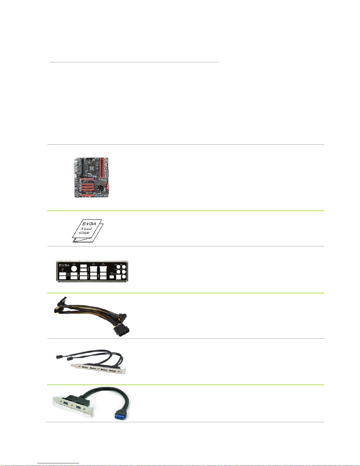
1–2-Port USB 3.0 Bracket
Allows Addition of 2 USB 3.0 ports by connecting to the
motherboard header.
EVGA Z77 FTW Motherboard
9
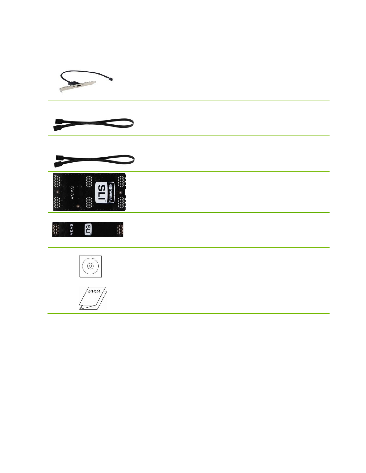
1–1394A Firewire Bracket
Allows addition of firewire 1394A output by connecting to the
motherboard header.
2–SATA II/3G Data Cables
Used to support the SATA protocol and each one connects a
single drive to the motherboard.
2–SATA III/6G Data Cables
Used to support the SATAIII/6G high speed protocol and each
one connects a single drive to the motherboard.
1- 3-way SLI Bridge
Bridges three (3) graphics cards together which allows for
3-way SLI.
1- 2-way SLI Bridge
Bridges two (2) graphics cards together which allows for
2-way SLI.
1- Installation CD
Contains drivers that are needed to setup the motherboard.
1–User Manual
Contains Information needed to properly install and configure
your EVGA Motherboard.

EVGA Z77 FTW Motherboard
10
Hardware Installation
This section will guide you through the installation of the motherboard. The
topics covered in this section are:
Preparing the motherboard
Installing the CPU
Installing the CPU fan
Installing the memory
Installing the motherboard
Connecting cables
Safety Instructions
To reduce the risk of fire, electric shock, and injury, always follow basic
safety precautions.
Remember to remove power from your computer by disconnecting the
AC main source before removing or installing any equipment from/to the
computer chassis.

EVGA Z77 FTW Motherboard
11
Preparing the Motherboard
Installing the CPU
Be very careful when handling the CPU. Hold
the processor only by the edges and do not
touch the bottom of the processor.
Use the following procedure to install the CPU
onto the motherboard:
Unhook the socket lever by pushing down and
away from the socket.
Pull the socket lever back and the load plate will
automatically lift. There is a protective
socket cover within the CPU socket to
protect the socket when there is no CPU
installed.
Remove the protective socket cover from the
CPU Socket.
Note: After removing the CPU socket cover, it is recommended that you keep it
in case you need to remove the CPU so for any reason you can replace
the cover to avoid damaging the CPU socket pins.

EVGA Z77 FTW Motherboard
12
Align the notches in the processor with the
notches on the socket.
Lower the processor straight down into the socket
without tilting or sliding it into the socket.
Note: Make sure the CPU is fully seated and level in
the socket.
Close the load plate over the CPU and press
down while you close and engage the
socket lever.
The CPU installation is complete.
Installing the CPU Fan
There are many different fan types that can be used with this motherboard.
Follow the instruction that came with your fan assembly. Be sure that the fan
orientation is correct for your chassis type and your fan assembly.
Align notches with notches on the CPU

EVGA Z77 FTW Motherboard
13
Installing System Memory (DIMMs)
Your new motherboard has four 240-pin slots for DDR3 memory. These slots
support 1GB, 2GB and 4GB DDR3 DIMMs. There must be at least one
memory slot populated to ensure normal operation. Use the following the
recommendations for installing memory.
One DIMM: If using 1 DIMM (Single Channel), install into: DIMM slot 2.
Two or Four DIMMs: If using 2 DIMMs (Dual Channel), install into:
DIMM slots 2 and 4. If using 4 DIMMs (Dual Channel), install into:
DIMM slots 1, 2, 3, and 4.
Use the following procedure to install DIMMs. Note that there is only one
gap near the center of the DIMM slot. This slot matches the slot on the
DIMM to ensure the component is installed properly.
1. Unlock a DIMM slot by pressing the module clips outward.
Align the memory module to the DIMM slot, and insert the module vertically
into the DIMM slot. The plastic clips at both sides of the DIMM slot
automatically lock the DIMM into the connector.
DIMM Slot 1
DIMM Slot 2
DIMM Slot 3
DIMM Slot 4

EVGA Z77 FTW Motherboard
14
Installing the Motherboard
The sequence of installing the motherboard into a system case depends on the
chassis you are using and if you are replacing an existing motherboard or
working with an empty system case. Determine if it would be easier to make all
the connections prior to this step or to secure the motherboard and then make
all the connections. It is normally easier to secure the motherboard first.
Use the following procedure to install the I/O shield and secure the
motherboard into the chassis.
Note: Be sure that the CPU fan assembly has enough clearance for the system
case covers to lock into place and for the expansion cards. Also make sure
the CPU Fan assembly is aligned with the vents on the covers. This will
depend on the system case being used.
Installing the I/O Shield
The motherboard kit comes with an I/O shield that is used to block radio
frequency transmissions, protects internal components from dust and foreign
objects, and promotes correct airflow within the chassis.
Before installing the motherboard, install the I/O shield from the inside of the
chassis. Press the I/O shield into place and make sure it fits securely. If the
I/O shield does not fit into the chassis, you would need to obtain the proper
size from the chassis supplier.
Also Note that for ease of installation you may want to install I/O shield Fan
(optional) before installing into case.

EVGA Z77 FTW Motherboard
15
Securing the Motherboard into a System Case
Most system cases have a base with mounting studs or spacers to allow the
motherboard to be secured to the chassis and help to prevent short circuits. If
there are studs that do not align with a mounting hole on the motherboard, it is
recommended that you remove that stud to prevent the possibility of a short
circuit. In most cases, it is recommended to secure the motherboard using a
minimum of nine (9) spacers and screws.
1. Carefully place the motherboard onto the stand offs located inside the chassis.
2. Align the mounting holes with the stand offs.
3. Align the connectors to the I/O shield.
4. Ensure that the fan assembly is aligned with the chassis vents according to the fan
assembly instruction.
5. Secure the motherboard with a recommended minimum of nine (9) screws.
Connecting Cables
This section takes you through all the necessary connections on the
motherboard. This will include:
Power Connections
24-pin ATX power (ATX_PWR_24)
8-pin ATX 12V power (ATX_PWR_SP1 & ATX_PWR_SP)
Internal Headers
Front Panel Header
IEEE 1394a Header
USB Headers
Audio Header
SATA II
SATA III
Chassis Fans
USB 2.0

EVGA Z77 FTW Motherboard
16
USB 3.0
Expansion slots
CMOS Clear Button
24-pin ATX Power (PWR_24)
PWR_24 is the main power supply connector located along the edge of the
board next to the DIMM slots. Make sure that the power supply cable and pins
are properly aligned with the connector on the motherboard. Firmly plug the
power supply cable into the connector and make sure it is secure.
Figure 1. PWR_24 Motherboard Connector
Table 1. PWR_24 Pin Assignments
Connector
Pin
Signal
Pin
Signal
1
+3.3V
13
+3.3V
2
+3.3V
14
-12V
3
GND
15
GND
4
+5V
16
PS_ON
5
GND
17
GND
6
+5V
18
GND
7
GND
19
GND
8
PWROK
20
RSVD
9
+5V_AUX
21
+5V
10
+12V
22
+5V
11
+12V
23
+5V
12
+3.3V
24
GND
PWR_24 connector
Plug power cable from system
power supply to PW1
Board edge
24
13
12
1
EVGA Z77 FTW Motherboard
17
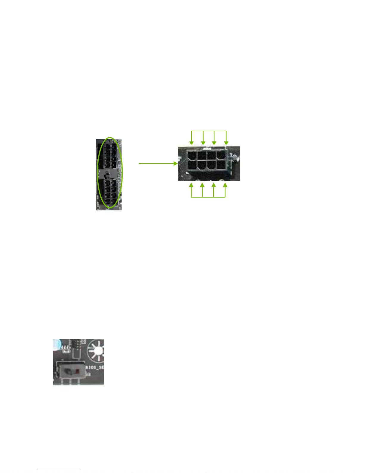
8-pin ATX 12V Power (ATX_PWR_SP1 & ATX_PWR_SP)
PW12-1 & PW12-2, the 8-pin ATX 12V power connection, is used to provide
power to the CPU. Align the pins to the connector and press firmly until seated.
BIOS Select Switch
The BIOS Select Switch is located directly to the right of the PC speaker on the lower
edge of the mainboard. This jumper controls which of physical BIOS chips are to be
used when the system is powered on.
The addition of 3 physical BIOS chips on the mainboard allows for usage of three
completely different bios versions or saving of profiles to differentiate between bench
sessions and regular 24/7 usage.
+12V
GND
EVGA Z77 FTW Motherboard
18
Connecting Internal Headers
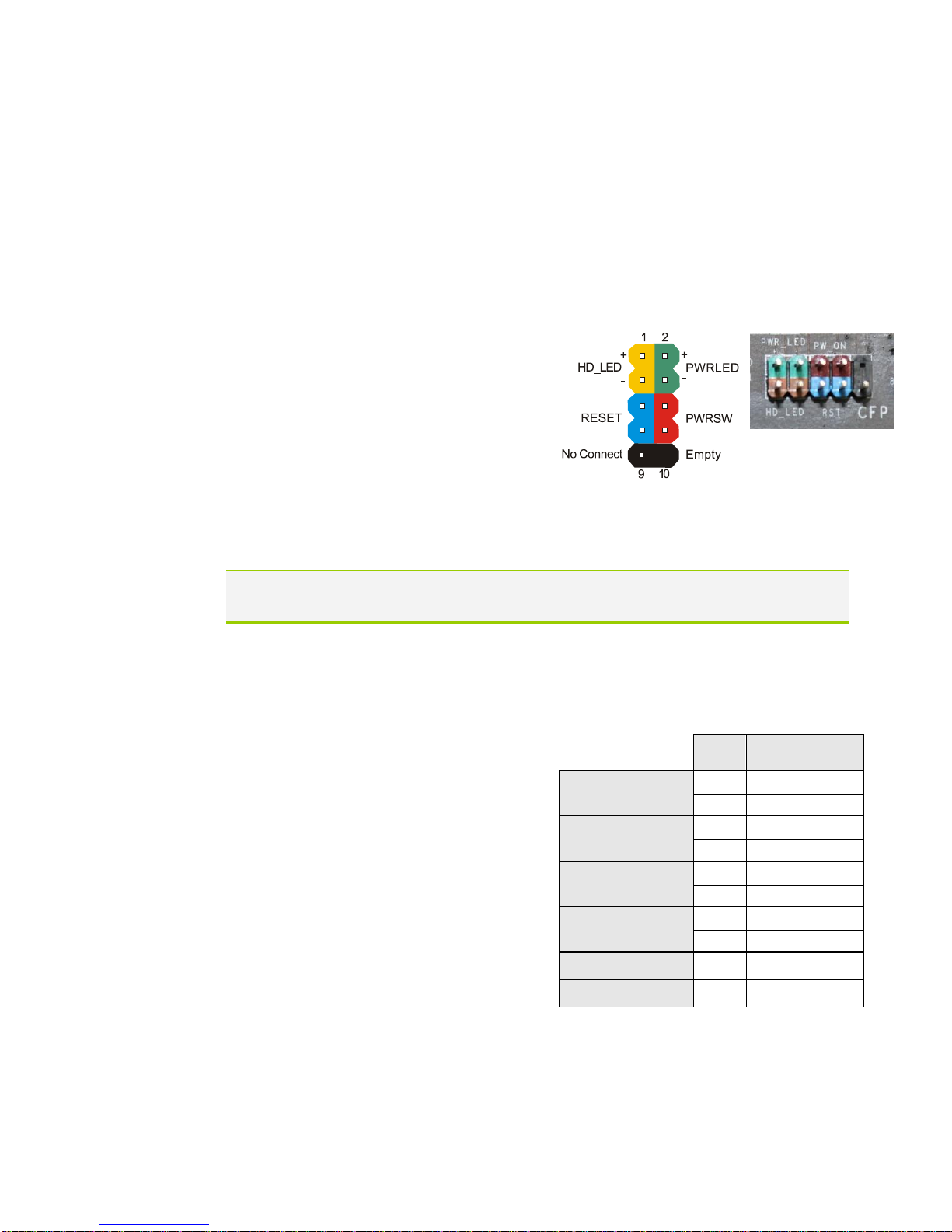
Front Panel Header
The front panel header on this motherboard is one connector used to connect
the following four cables.
(see Table 2 for pin definitions):
PWRLED
Attach the front panel power LED
cable to these two pins of the
connector. The Power LED indicates
the system’s status. When the system is
powered on, the LED will be on.
When the system is turned off, the
LED is off. When the system is in S1,
S3,
S4 status, the LED will blink.
Note: Some system cases do not have all four cables. Be sure to match the
name on the connectors to the corresponding pins.
PWRSW
Attach the power button cable from
the case to these two pins. Pressing
the power button on the front panel
turns the system on and off rather
than using the onboard button.
HD_LED
Attach the hard disk drive indicator
LED cable to these two pins. The
HDD indicator LED indicates the
activity status of the hard disks.
RESET
Attach the Reset switch cable from
the front panel of the case to these
two pins. The system restarts when
the RESET switch is pressed.
Table 2.Front Panel Header Pins
Pin
Signal
HD_LED
1
HD_PWR
3
HD Active
PWRLED
2
PWR LED
4
STBY LED
RESET
5
Ground
7
RST BTN
PWRSW
6
PWR BTN
8
Ground
No Connect
9
+5V
Empty
10
Empty

EVGA Z77 FTW Motherboard
19
IEEE 1394a (Firewire)
The IEEE 1394a expansion cable bracket is provided in the box but if you do
not require the additional external connections, you do not need to install it.
1. Secure the bracket to either the front or rear panel of the system case (not
all system cases are equipped with the front panel option).
Connect the end of the cable(s) to the IEEE 1394a headers on the
motherboard.
Table 3. IEEE 1394a Connector Pins
Connector
Pin
Signal
IEEE 1394a Connector
1
TPA+
2
TPA-
3
GND
4
GND
5
TPB+
6
TPB-
7
+12V
8
+12V
9
Empty
10
GND
10
8
6
4
2
9
7
5
3
1
Board
Edge

EVGA Z77 FTW Motherboard
20
USB Headers
This motherboard contains six (6) USB 2.0
ports that are exposed on the rear panel of the
chassis. The motherboard also contains two 10-
pin internal header connectors onboard that can
be used to connect an optional external bracket
containing up to four (4) USB 2.0 ports.
1. Secure the bracket to either the front or rear panel
of your chassis (not all chassis are equipped with the
front panel option).
2. Connect the two ends of the cables to the USB 2.0
headers on the motherboard.
Table 4. USB 2.0 Header Pins
Connector
Pin
Signal
USB 2.0 Header Connector
1
5V_DUAL
3
D-
5
D+
7
GND
9
Empty
Pin
Signal
2
5V_DUAL
4
D-
6
D+
8
GND
10
No Connect
Other manuals for Z77 FTW
1
Table of contents
Other EVGA Motherboard manuals

EVGA
EVGA EVGA X79 DARK User manual

EVGA
EVGA nForce 780i SLI FTW User manual

EVGA
EVGA X299 DARK User manual

EVGA
EVGA P67 SLI Micro User manual

EVGA
EVGA 141-GT-E770-A1 User manual

EVGA
EVGA X570 FTW Reference manual

EVGA
EVGA P55 Micro V User manual

EVGA
EVGA 111-CD-E630-TR User manual

EVGA
EVGA X79 Classified User manual

EVGA
EVGA P55 LE User manual

EVGA
EVGA Z77 Stinger System manual

EVGA
EVGA X99 Micro2 User manual

EVGA
EVGA nForce 4 User manual

EVGA
EVGA 122-M2-NF59-TR User manual

EVGA
EVGA P67 FTW Owner's manual

EVGA
EVGA X99 User manual

EVGA
EVGA P67 FTW User manual

EVGA
EVGA X299 Micro ATX 2 User manual

EVGA
EVGA X58 SLI3 User manual

EVGA
EVGA nForce 750i User manual


