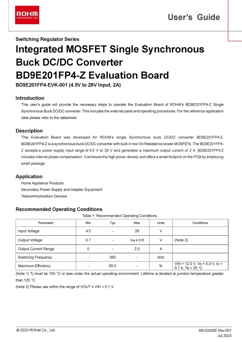
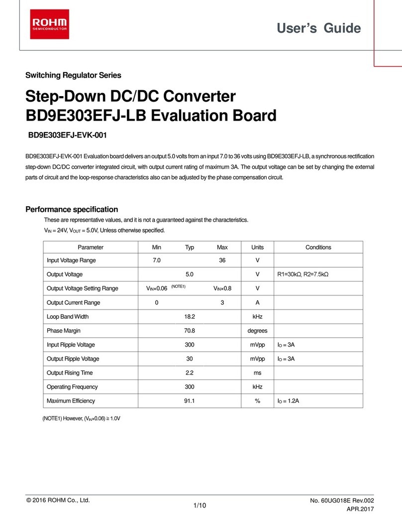
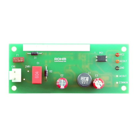
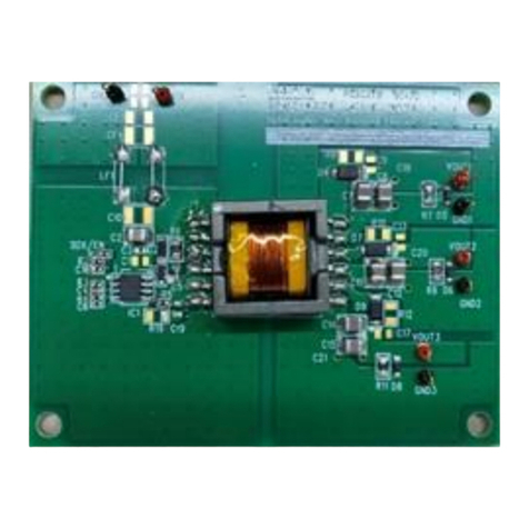
manuals.online logo
Brands
  1. Home
  2. •
  3. Brands
  4. •
  5. Rohm
  6. •
  7. Motherboard
  8. •
  9. Rohm BM2P0161-EVK-003 User manual

Rohm BM2P0161-EVK-003 User manual

1/20
© 2018 ROHM Co., Ltd. No. 60UG092E Rev.00
1
JULY.
2018
User’s Guide
AC/DC Converter
Isolation Fly-back Converter PWM method Output 24W 12V
BM2P0161 Reference Board
BM2P0161-EVK-003
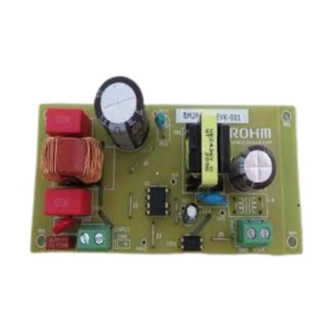
ROHM BM2P0161-EVK-003 is from wide input voltage (90Vac
〜
264Vac) to output 12V 2A max. Constant Voltage Reference board.
It used to
PWMmethodDC/DC
ConverterIC
BM2P0161.
BM2P0161 is including 650V High voltage power MOSFET and starter. The starter realize low Stand-by Power.Output voltage control method is
usedcurrent moderegulation,
therefore it can used cycle bycycle currentlimit.Quick response in dynamic load changing is achieved.
Switching frequency is fixed 65 kHz. Light load situation has frequency decrease function for
higher efficiency. Switching frequency jitter function
enables lower EMI operation. Various functions areincluded for safety, Softstart,Frequency Burst Mode, VCCOVP, Output OLP and thermalshut
down.
Electronics Characteristics
Not guarantee the characteristics, is representative value. Unless otherwise noted: V
IN
= 230Vac, I
OUT
= 500mA, Ta: 25°C
Table 1. Evaluation Board Specification
Description Min Typ Max Units Conditions
Input Voltage Range 90 - 264 Vac
Input Frequency Range 47 50/60 63 Hz
Output Voltage 10.8 12.0 13.2 V
Output Maximum Power - - 24 W I
OUT
=2A
Output Current Range 0.0 1.5 2.0 A (Note 1)
No Load Power Consumption - 73 - mW I
OUT
= 0A
Efficiency 80.0 86.0 - % Output:24V 1.5A
Output Ripple Voltage - 190 - mV BW=20MHz, (note 2)
(NOTE1) Please adjust operating time, within any parts surface temperature under 105°C
(NOTE2) Not include spike noise
2/20
© 2018 ROHM Co., Ltd. No. 60UG092E Rev.00
1
JULY.
2018
User’s Guide
BM2P0161
-
EVK
-
00
3
Operation Procedure
1. Operation Equipment
(1) AC Power supply 90Vac
~
264Vac, over 100W
(2) Electronic Load capacity 2A
(3) Multi meter
2. Connect method
(1) AC power supply presetting range 90~264Vac, Output switch is off.
(2) Load setting under 2A. Load switch is off.
(3) AC power supply N terminal connect to the boardAC (N) of CN1, and L terminal connect to AC (L).
(4) Load + terminal connect to VOUT, GND terminal connect to GND terminal
(5) AC power meter connect between AC power supply and board.
(6) Output test equipment connects to output terminal
(7) AC power supply switch ON.
(8) Check that output voltage is 12V.
(9) Electronic load switch ON
(10) Check output voltage drop by load connect wire resistance
Figure 1. Connection Circuit
Deleting
Maximum Output Power Po of this reference board is 24W. The derating curve is shown on the right. Please adjust load
continuous time by over 105°C of any parts surface temperature within the operating temperature range (-10~65°C).
Figure 2. Temperature Deleting curve
Ta[℃]
Po[W]
-10℃ 25℃ 50℃ 65℃
30W
24W
-
+
DC Multi Meter
V
Electric
LOAD
Power
Meter
AC power
Supply
24W
30W
3/20
© 201
8 ROHM Co., Ltd. No. 60UG092E Rev.00
1
JULY.2018
User’s Guide
BM2P0161
-
EVK
-
00
3
Schematics
VIN = 90~264Vac, VOUT = 12V
Figure 3. BM2P0161-EVK-003 Schematics
Bill of Materials Table 2. BoM of BM2P0161-EVK-003
C1
0.1μF
X1
LF1
13mH
F1
1.6A
AC300V
DB1
R4
0.43
±1%
2W
C9
1000pF
100V
C10
10μF
35V
R5
5.6
0.25W
T1
EE25
1
2
3
5
4
7
GND
D3
SBD 10A/150V
RB088BGE150
(TO-252)
C5
47μF
450V
SGND
IC2
TLP431B
C11
0.1μF
100V
R12
10k
±1%
R15
27k
R14
1k
R13
2.2k
R10
33k
±1%
R11
5.6k
±1%
VOUT
GND
PC1
C7
47pF
1kV
L
N
CN1-3
CN1-2
IC1
BM2P0161
VCC
1
N.C
N.C.
DRAIN
FB
GND_IC
FADJ
SOURCE
2
3
4
8
7
6
5
9
C13
1000μF
25V
Low-Z
C15
0.1μF
100V
C6
1000pF
1kV
R7
100k
2W
C11
2200pF
Y1
ZNR1 C2
0.1μF
X1
R6
0
C8
NC.
8
6
12V/2A
D1
FRD
0.8A/700V
RFN1LAM7S
(PMDTM)
D2
SBD
0.2A/400V
RRE02VSM4S
(TUMD2SM)
Part
Reference
Qty. Type Value Description Part Number Manufacture Configuration
mm (inch)
C1,C2 2 X2 Capacitor 0.1μF 300Vac, ±20% 890324023023CS Wurth -
C5 1 Electrolytic 47μF 450V, ±20% 450BXW47MEFR16X25 Rubycon 16mmΦX25mm
C6 1 Ceramic 2200pF 1000V, X7R, ±10% GRM31BR73A222KW01 Murata 3216 (1206)
C7 1 Ceramic 47pF 1000V, X7R, ±10% RDE5C3A470J2K1H03B Murata -
C8 0 Ceramic NC - - - 1608 (0603)
C9 1 Ceramic 1000pF 100V, X7R, ±10% HMK107B7102KA-T Taiyo Yuden 1608 (0603)
C10 1 Ceramic 10μF 35V, ±10% GMK316AB7106KL-TR Taiyo Yuden 3216 (1206)
C11 1 Y1 Capacitor 2200pF Y1 capacitor DE1E3KX222MB4BP01F Murata -
C13 1 Electrolytic 1000uF 25V , ±20% 25ZLJ1000M10X20 Rubycon 10mmΦX20mm
C15,C16 2 Ceramic 0.1μF 100V, X7R, ±10% HMK107B7104KA-T Taiyo Yuden 1608 (0603)
D1 1 FRD 0.8A 700V RFN1LAM7S ROHM PMDTM
D2 1 REC Di 0.2A 400V RRE02VSM4S ROHM TUMD2SM
D3 1 SBD 10A 150V RB088BGE150 ROHM TO-252
DB1 1 Bridge 1A 800V D1UBA80 Shindengen SOP-4
F1 1 Fuse 1.6A 1.6A 300V 36911600000 Littelfuse -
IC1 1 AC/DC Converter - 650V BM2P0161 ROHM DIP7
IC2 1 Shunt Regulator - ±0.5% TL431BIDBZT TI SOT-23-3
LF1 1 Line Filter 13mH 1A XF1482Y Alpha Trans -
PC1 1 Optocoupler - 5kV LTV-817-B LiteON DIP4
T1 1 Transformer - Bobin:EI-2506,
Core:EE25/20 XE2181A Alpha Trans -
R4 1 Resistor 0.43Ω 2W, ±1% LTR100JZPFLR430 ROHM 3264 (1225)
R5 1 Resistor 5.6Ω 0.25W, ±5% MCR18EZPJ5R6 ROHM 3216 (1206)
R6 1 Resistor 0Ω 0.25W MCR18EZPJ000 ROHM 3216 (1206)
R7 1 Resistor 100kΩ 2W, 700V, ±2% ERG2SJ104E Panasonic -
R10 1 Resistor 33kΩ 0.1W, ±1% MCR03EZPFX3302 ROHM 1608 (0603)
R11 1 Resistor 5.6kΩ 0.1W, ±1% MCR03EZPFX5601 ROHM 1608 (0603)
R12 1 Resistor 10kΩ 0.1W, ±1% MCR03EZPFX1002 ROHM 1608 (0603)
R13 1 Resistor 2.2kΩ 0.1W, ±5% MCR03EZPF222 ROHM 1608 (0603)
R14 1 Resistor 1kΩ 0.1W, ±5% MCR03EZPJ102 ROHM 1608 (0603)
R15 1 Resistor 27kΩ 0.1W, ±5% MCR03EZPJ273 ROHM 1608 (0603)
ZNR1 1 Varistor - 300Vac, 423Vmin, 400A V470ZA05P Littelfuse 5mmΦ Disc
4/20
© 201
8 ROHM Co., Ltd. No. 60UG092E Rev.00
1
JULY.2018
User’s Guide
BM2P0161
-
EVK
-
00
3
Design reference of transformer
Manufacturer :Alfatrans Co., LTD.
〒541-0059 2-7-1 bakurou-cho, chu-o ku, osaka
http://www.alphatrans.jp/
Product: XE2145AAlphaTrans Corp.
Bobin: EI-2506 10PIN
Core: EE25/20 JSF
Figure 4. Connection Diagram Figure 5. Winding structure diagram
Table 3. Alpha Trans XE2145A Winding Specification
Inductance (Lp) 830µH±15% (100kHz,1V)
Leakage Inductance 25µH MAX
Withstand Voltage Pri – Sec AC3000V
Pri - Core AC1500V
Sec – Core AC1500V
Insulation resistance 100MΩover (DC500V)
5/20
© 201
8 ROHM Co., Ltd. No. 60UG092E Rev.00
1
JULY.2018
User’s Guide
BM2P0161
-
EVK
-
00
3
PCB
Size : 55 mm x 91 mm
Figure 4. Top Silkscreen (Top view)
Figure 5. Bottom Layout (Top view)
6/20
© 2018 ROHM Co., Ltd. No. 60UG092E Rev.00
1
JULY.
2018
User’s Guide
BM2P0161
-
EVK
-
00
3
BM2P0161 Overview
Feature

PWM Frequency=65kHz

PWM current Mode Control

Switching frequency jitter

Burst function around light load

Burst frequency control adjust
(
FADJ
)

650 V Starter

650 V Power MOSFET

VCC
OVP, UVLO

SOURCE Comparator Leading-Edge-Blanking

Cycle by cycle current limiter

Current limiter AC Voltage compensation circuit

Soft Start function

OLP
、
Thermal shut down
Key specifications
■
Operation Voltage Range:
VCC: 8.9 V
〜
26.0 V
DRAIN: 650 V(Max)
■
Circuit Current(ON) :
BM2P0161: 0.90 mA(Typ)
BM2P0361: 0.65 mA(Typ)
■
Circuit Current (Burst mode) : 0.30 mA(Typ)
■
Operating Temperature: -40 °C
〜
+105 °C
■
Maximum Junction Temperature : +150 °C
■
MOSFET R-ON : BM2P0161 : 1.0
Ω
(Typ)
BM2P0361 : 3.0

(Typ)
Dimension
W(Typ) x D(Typ) x H(Max)
DIP7K 9.20 mm x 6.35 mm x 4.30 mm
Pitch 2.54 mm
Figure 8. Block Diagram
Figure 9. DIP7K Package
Table 4. BM2P0161 PIN description
NO. Name I/O Function ESD Diode
VCC
GND
1 SOURCE I/O MOSFET SOURCE
✔
✔
2 FADJ I Max Burst Frequency Setting pin
✔
✔
3 GND I/O GND
✔
-
4 FB I Feedback signal input
✔
✔
5 VCC I Vcc -
✔
6 DRAIN I/O MOSEFET DRAIN - -
7 DRAIN I/O MOSEFET DRAIN - -
GND
DRAIN DRAIN VCC
SOURCE
7 6 5
1 2 3 4
FADJ FB
TOP VIEW
7/20
© 201
8 ROHM Co., Ltd. No. 60UG092E Rev.00
1
JULY.2018
User’s Guide
BM2P0161
-
EVK
-
00
3
Design Overview
1. Important parameter
Input Voltage Spec AC90V to AC264V (DC 100V to 380V)
MOSFET Voltage max 650V
1-1.Determination of fly-back voltage VOR
Turns-ratio Np:Ns and duty-ratio is determined along with Fly-back voltage VOR

 


* 1.3: Safety margin. Please check yourself.



!"#$ 
%
&'(
Figure 10. MOSFET Drain-Source Voltage (Vds)
Confirmation of Np/Ns and Duty (max)
)&'(
VIN (MIN) =100V, VOR=70V, Vf=1V


 
*%)
(%'
(*) VOR should be set to keep margin from input Max voltage plus VOR and MOSFET maximum ratings.
And VOR setting also keep MOSFET on duty within 0.5 at input voltage minimum.


 
*%)
(%'
!"#$
+,% )
%)-(
VIN→
GND→
VOR
8/20
© 2018 ROHM Co., Ltd. No. 60UG092E Rev.00
1
JULY.
2018
User’s Guide
BM2P0161
-
EVK
-
00
3
1-2
.
Selecting operation mode
Flyback converter of fixed frequency PWM switching send power from primary side to secondary side using
Transformer. Transformer operation mode are blow three modes.

CCM
(
Continuous Current Mode
)
Primary MOSFET turn ON before secondary coil discharge complete.

BCM
(
Boundary Current Mode
)
Primary MOSFET turn ON timing is just secondary coil discharge. Mode
name from looks like bounding ball, secondary current wave form touch to GND at the same time primary coil
current grow-up from GND.

DCM
(
Dis-continuous Current Mode
)
Primary MOSFET turn ON timing has some interval after secondary coil
discharge. Coil current is dis-continue.
BM2P0161 can be operate CCM, BCM and DCM.
This reference board transformer design target is BCM point at input DC260V (185V) and LOAD 12V/2A.
Figure 11. Switching waveform (MOSFET Vds,Ids)
Figure 12. Operation mode – Input Voltage and Peak current (MOSFET Drain, Diode)
BCM
BCMBCM
BCM
DCM
DCMDCM
DCM
Operating wave form of MOSFET
Drain voltage and current.
Primary
MOSFET Drain
Peak Current
Input
Voltage
CCM DCM
BCM
Point
Vds
Ids
Vds
Ids
Vds
Ids
Secondary
Diode
Peak Current
Input
Voltage
CCM
DCM
BCM
Point
9/20
© 2018 ROHM Co., Ltd.
No. 60UG092E Rev.00
1
JULY.
2018
User’s Guide
BM2P0161
-
EVK
-
00
3
1-3. Design of transformer inductances
Assuming condition BCM point is 260VDC
、
65kHz 12V/2A load.
Calculation for secondary and primary inductance, peak current.
Vo=12V
、
secondary rectifier diode VF
=
1V
./(%(0(1
!"#$ 
% )
(%)((
23 /4*5
6

(7(%((
6
((89(':;
2<23

6
(':;'
6
'=;
>3<?@(A
B7 8
><<?@(A
B7 C'(0
><D><<?4*5
EC'(((
E(8
1-4
.
Selecting transformer core size
Accordingly Po (max) =26W, Core is selected EE25.
Table 5. Output Power vs transformer core size
(*)
above table is one of reference, please confirmation to transformer manufacturer.
1-5
.
Calculate of primary wiring turn : Np
The maximum rating of magnetic flux density of standard ferrite core is
0.4T@100
℃
. Accordingly Bsat=0.266T.
F<GB9
8HIJ':;C'(8
-==
6
(K)#"L,3
Np makes 77 turns.
Prevent form Magnetic saturation.
Check transformer AL-Value
-
NI value table
。
When Np=77 turns,
02M"N 

6
':;
))*O
6
C;P*O
6
F>F<><<?))#"L,3C'(0)(0Q#"L,3
Confirm by core specification whether or not it falls into this saturation region.
Output Power Po(W) Core Size Core Area Ae
(
mm
2)
~30 EI25/EE25 41
~60 EI28/EE28/EER28 84
~80
EI33/EER35
107
Figure 13. TDK PC47EE25/19
AL-Value to NI Limit
10/20
© 201
8 ROHM Co., Ltd. No. 60UG092E Rev.00
1
JULY.2018
User’s Guide
BM2P0161
-
EVK
-
00
3
1-6.Calculate of secondary wiring turn : Ns

'R ))
'-*O
Ns wiring is 14 turns.
Secondary wiring average current is output current.
1-7.Calculation of VCC wiring turn ; Nd
Accumulation VCC=16V、Vf_vcc diode =1V
FSF3TT%UVWW
*% -*O%
(%'#"L,3
Nd wiring is 18 turns.
(*) Please consider secondary capacitor voltage ratings and VCC OVP voltage.
Transformer parameter of this section result.
Table 6. Transformer parameter table
Core PC47EE25/19 compatible
Lp 830µH
Np 77 turns
Ns 14 turns
Nd 18 turns
2.Selection of important components
2-1.Input capacitor;C5
Calculation by using of Table 1-3
Pout=12Vx2.0A=24W, C5:2x24=48  47F
Table 7. Input capacitor selection table
Input Voltage
(Vdc)Cin(µF)
< 300 2 x Pout(W)
300<
1 x Pout(W)
(*)When selecting, also consider other specifications such as the output retention-time.
Capacitor voltage rating is selected by maximum input voltage.
This time we selected 450V ratings capacitor.
11/20
© 201
8 ROHM Co., Ltd. No. 60UG092E Rev.00
1
JULY.2018
User’s Guide
BM2P0161
-
EVK
-
00
3
2-2.Current sensing resistor;R4
The current-sensing resistor and current limiter is set maximum output power.
-W%(=X*5P7
9 -%(((P
Y
C'(8 -)
R4 is selected 0.43.
Calculation of R4 power loss
.
Z[\]^_
9
6
 -C'(
6
8-`-a
.
Z[bcd
><D-((0-`C(1
Set the value 1W or above in consideration of pulse resistance.
The structure of the resistance may vary the pulse resistance even with the same power rating.
Check with the resistor manufacturers for details.
2-3.VCC diode ;D2
A high-speed diode (Small size rectifier or fast recovery diode) is recommended as the VCC-diode.
Diode current is only IC current, it maximum value is around 15mA.
When D2_Vf=1V, reverse voltage applied to the VCC-diode:
SLee%f%>FX

This IC has VCC OVP function, VCC OVP (max) =29.0V.
Reverse voltage of the diode is set so as not to exceed the Vr of diode in conditions of VCC OVP (max).
SL(C%%--*O
))*O
With a design-margin taken into account, selected RRE02VSM4S 0.2A/400V
2-4.VCC winding surge-voltage limiting resistor;R5
Based on the transformer’s leakage inductance (Lleak), a large surge-voltage (spike noise) may occur during the instant when
the MOSFET is switched from ON to OFF. This surge-voltage is induced in the VCC winding, and as the VCC voltage increases
the IC’s VCC overvoltage protection may be triggered.
A limiting resistor R5 (approximately 5to 22) is inserted to reduce the surge-voltage that is induced in the VCC winding.
Confirm the rise in VCC voltage while the resistor is assembled in the product.
12/20
© 201
8 ROHM Co., Ltd. No. 60UG092E Rev.00
1
JULY.2018
User’s Guide
BM2P0161
-
EVK
-
00
3
0.0
0.1
0.2
0.3
0.4
0.5
0.6
0.7
0.8
0.9
1.0
0 5 10 15 20 25 30 35 40 45 50
Start Time [s]
CVCC[µF]
2-5.VCC capacitor;C10
This IC is built-in starter. Therefore start up time is from VCC capacitor value. Starting time is bellows.
After start up. Consumption power is determined by idling current Istart3.
Capacitor Rating voltage setting is over and margin from VCC OVP voltage =29Vmax.
This board selecting value is 10uF/50V.
Figure 14. Start Up Current vs VCC Voltage Figure 15. Start Time vs CVCC
2-6.Snubber circuit ;C6,D1,R7
Based on the transformer’s leakage inductance (Lleak), a large surge-voltage (spike noise) may occur during
the instant when the MOSFET is switched from ON to OFF. This surge-voltage is applied between the MOSFET’s
Drain and Source, so in the worst case damage to MOSFET might occur. RCD snubber circuits are recommended to
suppress this surge-voltage.
(1) Determination of clamp voltage (Vclamp) and clamp ripple-voltage (Vripple)
The clamp voltage is determined by the MOSFET’s withstand voltage considering a design margin.
Vclamp=650V x 0.8 = 520V
Clamp voltage Ripple(Vripple)is set about 70V
(2) Determination of R7
R7 is selected according to the following conditions. (Consideration margin)
Assumption Lleak=Lp x 5% = 830uH x 5% = 42uH
)&(gM< WhJ=
BhHJ9
6
7(( ()
-(:C'(
6
9)'?`
R7 is selected 120k.
R7 Power loss ; P_R7
.
Zi
WhJ=
6
) (-
6
(9 (a
P_R7 is setting 1W including some margins.
0 10V VUVLO1
VSC
ISTART1
ISTART3
ISTART2
VCC Voltage [V]
Start Up Current [mA]
13/20
© 201
8 ROHM Co., Ltd. No. 60UG092E Rev.00
1
JULY.2018
User’s Guide
BM2P0161
-
EVK
-
00
3
(3) Determination of C6
eG WhJ=
OjhH7 )(
)9;k(9`C<l
C6 voltage is VOR- input maximum voltage 520V-400=120V + surge
This time capacitor value and voltage rating is set 1000pF/1kV. Considering surge voltage margins.
(4) Determination of D1
Choose a fast recovery diode as the diode, with a withstand voltage that is at or above the MOSFET’s Vds (max) value.
This time is selected RFN1LAM7S 0.8A/700V.
2-7.FB terminal capacitor:C9
C16 is a capacitor for stability of FB voltage (approximately 1000pF to 0.01F)
2-8.Output rectification diode :D3
Choose a high-speed diode (Schottky barrier diode or fast recovery diode) as the output rectification diode. When Vf=1V,
reverse voltage applied to output diode is,
SL/"#%Df%>F

When Vout(max)=12.0V+10%=13.2V
SL(%%--
))'C(
With consideration of margins 87/0.7=124V 150V
Also, diode loss (approximate value) becomes Pd=Vf x Iout=1.0V x 2A=2.0W
This board is used schottky barrier diode RB088BGE-150:150V 10A , TO-252 package
Using a voltage margin of 70% or less and current of 50% or less is recommended.
Check the rise in temperature while assembled in the product. If necessary, reconsider the component and radiate heat by a heat
sink or similar to dissipate the heat.
2-9.Output capacitors: C13, C15
Determine the output capacitors based on the output load‘s allowable peak-to-peak ripple voltage (Vpp) and ripple-current.
When the MOSFET is ON, the output diode is OFF. At that time, current is supplied to the load from the output capacitors. When
the MOSFET is OFF, the output diode is ON. At that time, the output capacitors are charged and a load current is also
supplied.
When Vpp = 200mV,
m
n
&o
9 o

9(
))
-C'(8)`J9;kp7+,
With an ordinary switching power supply electrolytic-capacitor (low-impedance component), impedance is rated at 100kHz, so it
is converted to 100kHz.
m
n
&)`
Yq
rss
(-`J9;k
14/20
© 201
8 ROHM Co., Ltd. No. 60UG092E Rev.00
1
JULY.2018
User’s Guide
BM2P0161
-
EVK
-
00
3
Ripple Current Is (rms) is
>3L3>3<?@4*5
))
-C'(8@((
()'8
C13 charge/Discharge Current Ic (rms) is
>gL3tO=
6

6
t()'
6
(
6
C8O=
The capacitor’s withstand voltage should be set to about twice the output voltage.
Vout x 2 = 12V x 2 = 24V  over 25V
Select an electrolytic capacitor that is suitable for these conditions.
The board is select capacitor as bellows.
C13 1000uF/25V Rubycon ZLJ Series Iripple 2500mA@100kHz Imp 0.028
C15 0.1uF/50V Ceramic Capacitor
(*)Use the actual equipment to check the actual ripple-voltage, ripple-current and capacitor-current.
2-10.Output voltage setting resistors: R10,R11,R12
Set the output voltage with the following formal
When Shunt regulator IC2: Vref=2.495V,
/u% % 
( vLNfu%?`%?`
9` v(-C(()
2-11.Parts for adjustment of control circuit:R15, C16, R13, R14
R15 and C11 are parts for phase compensation. Approximately R15:1k to 30k, C11=0.1uF, and adjust them while they are
assembled in the product.
R13 is a resistor which limits a control circuit current. Approximately R14:300 to 2k, and adjust it while it assembled in the
product. R14 is a resistor for adjustment of minimum operating current of shunt regulator IC2.
In case of IC2: TL431, minimum operating current is 1mA. And when Optocoupler:PC1_Vf is 1V, R14 = 1V / 1mA = 1k
3.EMI Measure
Confirm the following with regard to EMI countermeasures.
(*) Constants are reference values. Need to be adjusted based on noise effects.
- Addition of filter to input block C1, C2, LF1
- Addition of capacitor between primary-side and secondary-side (approximately C11: Y-Cap 2200pF)
- Addition of RC snubber to secondary diode
15/20
© 201
8 ROHM Co., Ltd. No. 60UG092E Rev.00
1
JULY.2018
User’s Guide
BM2P0161
-
EVK
-
00
3
Measurement DATA
・Constant Load Regulations
Figure 16. Load Regulation (IOUT vs. VOUT) Figure 17. Load Regulation (IOUT vs. Efficiency)
Table 8. Load Regulation (VIN=90Vac) Table 9. Load Regulation (VIN=230Vac)
I
OUT
V
OUT
Efficiency
500 mA
12.105 V
85.13 %
1000 mA
12.100 V
85.75 %
1500 mA
12.096 V
85.58 %
2000 mA
12.090 V
84.75 %
Figure 18. Load Regulation (IOUT vs. PLOSS) Figure 19. Load Regulation (IOUT vs. PLOSS)
10.8
11.2
11.6
12.0
12.4
12.8
13.2
0 1000 2000 3000
Output Voltage [V]
Output Current [mA]
-VIN= 90Vac
-
VIN=115Vac
-VIN=230Vac
-VIN=264Vac
0
10
20
30
40
50
60
70
80
90
100
0 500 1000 1500 2000
Efficiency [%]
Output Current [mA]
-VIN= 90Vac
-VIN=230Vac
-VIN=115Vac
-VIN=264Vac
0.0
0.5
1.0
1.5
2.0
2.5
3.0
3.5
4.0
4.5
5.0
0 500 1000 1500 2000
Power Loss [W]
Output Current [mA]
-VIN= 90Vac
-VIN=230Vac
-VIN=115Vac
-
VIN=264Vac 0.00
0.05
0.10
0.15
0.20
0.25
0.30
0.35
0.40
0.45
0.50
1 10 100
Power Loss [W]
Output Current [mA]
-VIN= 90Vac
-VIN=230Vac
-VIN=115Vac
-
VIN=264Vac
I
OUT
V
OUT
Ef
ficiency
500 mA
12.105 V
83.14 %
1000 mA
12.100 V
84.62 %
1500 mA
12.095 V
86.11 %
2000 mA
12.090 V
86.73 %
16/20
© 201
8 ROHM Co., Ltd. No. 60UG092E Rev.00
1
JULY.2018
User’s Guide
BM2P0161
-
EVK
-
00
3
Table 10. Load Regulation : VIN=90Vac Table 11. Load Regulation: VIN=115Vac
Table 12. Load Regulation : VIN=132Vac Table 13. Load Regulation: VIN=176Vac
Table 14. Load Regulation : VIN=230Vac Table 15. Load Regulation: VIN=264Vac
V
IN
[Vac]
P
IN
[W]
V
OUT
[V]
I
OUT
[mA]
P
OUT
[W]
P
LOSS
[W]
Efficiency
[%]
90 0.04 12.110 0 0.00 0.042 0.00
90 0.12 12.110 5 0.06 0.057 51.31
90 0.20 12.110 10 0.12 0.077 61.16
90 0.36 12.110 20 0.24 0.115 67.84
90 0.51 12.110 30 0.36 0.150 70.82
90 0.82 12.110 50 0.61 0.211 74.20
90 1.10 12.109 70 0.85 0.249 77.27
90 1.52 12.109 100 1.21 0.305 79.87
90 2.91 12.108 200 2.42 0.486 83.27
90 7.11 12.105 500 6.05 1.058 85.13
90 9.89 12.103 700 8.47 1.418 85.66
90 14.11 12.100 1000 12.10 2.010 85.75
90 16.89 12.098 1200 14.52 2.372 85.95
90 21.20 12.096 1500 18.14 3.056 85.58
90 24.10 12.094 1700 20.56 3.540 85.31
90 28.53 12.090 2000 24.18 4.350 84.75
90 33.13 12.088 2300 27.80 5.328 83.92
90 OLP 0.000 2300
V
IN
[Vac]
P
IN
[W]
V
OUT
[V]
I
OUT
[mA]
P
OUT
[W]
P
LOSS
[W]
Efficiency
[%]
115 0.05 12.110 0 0.00 0.047 0.00
115 0.12 12.110 5 0.06 0.059 50.46
115 0.20 12.110 10 0.12 0.076 61.47
115 0.36 12.110 20 0.24 0.115 67.84
115 0.51 12.110 30 0.36 0.150 70.82
115 0.83 12.110 50 0.61 0.221 73.31
115 1.11 12.109 70 0.85 0.258 76.64
115 1.52 12.109 100 1.21 0.313 79.46
115 2.92 12.108 200 2.42 0.499 82.90
115 7.09 12.105 500 6.05 1.038 85.37
115 9.90 12.103 700 8.47 1.428 85.58
115 14.01 12.100 1000 12.10 1.910 86.37
115 16.85 12.098 1200 14.52 2.332 86.16
115 20.99 12.096 1500 18.14 2.846 86.44
115 23.85 12.094 1700 20.56 3.290 86.20
115 28.10 12.091 2000 24.18 3.918 86.06
115 35.37 12.085 2500 30.21 5.158 85.42
115 OLP 0.000 2500
V
IN
[Vac]
P
IN
[W]
V
OUT
[V]
I
OUT
[mA]
P
OUT
[W]
P
LOSS
[W]
Efficiency
[%]
132 0.04 12.110 0 0.00 0.043 0.00
132 0.12 12.110 5 0.06 0.063 48.83
132 0.20 12.110 10 0.12 0.074 62.10
132 0.36 12.110 20 0.24 0.116 67.65
132 0.51 12.110 30 0.36 0.151 70.68
132 0.83 12.110 50 0.61 0.225 72.95
132 1.12 12.109 70 0.85 0.270 75.82
132 1.54 12.109 100 1.21 0.326 78.78
132 2.94 12.108 200 2.42 0.518 82.37
132 7.12 12.105 500 6.05 1.068 85.01
132 9.85 12.103 700 8.47 1.378 86.01
132 14.06 12.100 1000 12.10 1.960 86.06
132 16.78 12.098 1200 14.52 2.262 86.52
132 20.88 12.096 1500 18.14 2.736 86.90
132 23.76 12.094 1700 20.56 3.200 86.53
132 27.99 12.090 2000 24.18 3.810 86.39
132 35.13 12.084 2500 30.21 4.920 85.99
132 OLP 0.000 2500
V
IN
[Vac]
P
IN
[W]
V
OUT
[V]
I
OUT
[mA]
P
OUT
[W]
P
LOSS
[W]
Efficiency
[%]
176 0.04 12.110 0 0.00 0.039 0.00
176 0.12 12.110 5 0.06 0.057 51.31
176 0.20 12.110 10 0.12 0.078 60.85
176 0.36 12.110 20 0.24 0.121 66.72
176 0.52 12.110 30 0.36 0.157 69.87
176 0.83 12.109 50 0.61 0.226 72.86
176 1.15 12.109 70 0.85 0.300 73.84
176 1.58 12.109 100 1.21 0.364 76.88
176 2.98 12.108 200 2.42 0.561 81.18
176 7.19 12.105 500 6.05 1.138 84.18
176 9.95 12.103 700 8.47 1.478 85.15
176 14.05 12.100 1000 12.10 1.950 86.12
176 16.89 12.098 1200 14.52 2.372 85.95
176 21.02 12.095 1500 18.14 2.878 86.31
176 23.67 12.093 1700 20.56 3.112 86.85
176 27.92 12.090 2000 24.18 3.740 86.60
176 34.94 12.085 2500 30.21 4.728 86.47
176 36.35 12.084 2600 31.42 4.932 86.43
176 OLP 0.000 2600
V
IN
[Vac]
P
IN
[W]
V
OUT
[V]
I
OUT
[mA]
P
OUT
[W]
P
LOSS
[W]
Efficiency
[%]
230 0.05 12.110 0 0.000 0.045 0.00
230 0.12 12.110 5 0.061 0.063 48.83
230 0.21 12.110 10 0.121 0.085 58.79
230 0.37 12.110 20 0.242 0.129 65.28
230 0.53 12.110 30 0.363 0.168 68.42
230 0.85 12.110 50 0.606 0.242 71.49
230 1.16 12.109 70 0.848 0.312 73.07
230 1.63 12.109 100 1.211 0.418 74.33
230 3.05 12.108 200 2.422 0.629 79.37
230 7.28 12.105 500 6.053 1.228 83.14
230 10.12 12.103 700 8.472 1.648 83.72
230 14.30 12.100 1000 12.100 2.200 84.62
230 17.01 12.098 1200 14.518 2.492 85.35
230 21.07 12.095 1500 18.143 2.928 86.11
230 23.95 12.093 1700 20.558 3.392 85.84
230 27.88 12.090 2000 24.180 3.700 86.73
230 35.02 12.085 2500 30.213 4.808 86.27
230 36.43 12.084 2600 31.418 5.012 86.24
OLP 0.000 2600
V
IN
[Vac]
P
IN
[W]
V
OUT
[V]
I
OUT
[mA]
P
OUT
[W]
P
LOSS
[W]
Efficiency
[%]
264 0.06 12.110 0 0.00 0.055 0.06
264 0.13 12.110 5 0.06 0.068 0.07
264 0.21 12.110 10 0.12 0.089 0.09
264 0.38 12.110 20 0.24 0.138 0.14
264 0.54 12.110 30 0.36 0.177 0.18
264 0.86 12.110 50 0.61 0.258 0.26
264 1.18 12.109 70 0.85 0.333 0.33
264 1.66 12.109 100 1.21 0.450 0.45
264 3.10 12.108 200 2.42 0.675 0.68
264 7.36 12.105 500 6.05 1.312 1.31
264 10.15 12.103 700 8.47 1.678 1.68
264 14.28 12.100 1000 12.10 2.180 2.18
264 17.06 12.098 1200 14.52 2.542 2.54
264 21.22 12.095 1500 18.14 3.078 3.08
264 24.02 12.093 1700 20.56 3.462 3.46
264 28.08 12.090 2000 24.18 3.900 3.90
264 35.19 12.084 2500 30.21 4.980 4.98
264 38.00 12.080 2700 32.62 5.384 5.38
264 OLP 0.000 2700
17/20
© 201
8 ROHM Co., Ltd. No. 60UG092E Rev.00
1
JULY.2018
User’s Guide
BM2P0161
-
EVK
-
00
3
・Switching Frequency
Figure 20. Switching Frequency (IOUT vs. FSW)
・Primary Peak Current ・Secondary Peak Current
Figure 21. Primary Peak Current (IOUT vs. IpPEAK) Figure 22. Primary Peak Current (IOUT vs. IsPEAK)
0
10
20
30
40
50
60
70
0 500 1000 1500 2000
Switching Frequency [kHz]
Output Current [mA]
-VIN=115Vac
-VIN=230Vac
0.0
0.1
0.2
0.3
0.4
0.5
0.6
0.7
0.8
0.9
1.0
1.1
1.2
1.3
0 500 1000 1500 2000
Primary Peak Current [A]
Output Current [mA]
-VIN=115Vac
-VIN=230Vac 0.0
1.0
2.0
3.0
4.0
5.0
6.0
7.0
0 500 1000 1500 2000
Secondary Peak Current [A]
Output Current [mA]
-VIN=115Vac
-VIN=230Vac
18/20
© 2018 ROHM Co., Ltd.
No. 60UG092E Rev.00
1
JULY.
2018
User’s Guide
BM2P0161
-
EVK
-
00
3
・
Operation Waveform
Figure 23. V
IN
=90Vac, I
OUT
=2A Figure 24. V
IN
=90Vac Output Short
Figure 25. V
IN
=115Vac, I
OUT
=2A Figure 26. V
IN
=115Vac Output Short
Figure 27. V
IN
=230Vac, I
OUT
=2A Figure 28. V
IN
=230Vac Output Short
Figure 29. V
IN
=264Vac, I
OUT
=2A Figure 30. V
IN
=264Vac Output Short
CH3 Purple MOSFET VDS
CH2 Blue MOSFET IDrain
CH4 Green Secondary Diode Vr
CH1 Yellow Secondary Diode If
19/20
© 2018 ROHM Co., Ltd.
No. 60UG092E Rev.00
1
JULY.
2018
User’s Guide
BM2P0161
-
EVK
-
00
3
・
Power ON
Figure 31. V
IN
=115Vac, R
OUT
=12

Figure 32. V
IN
=264Vac R
OUT
=12

・
Dynamic Response
Figure 33. V
IN
=115Vac, I
OUT
=10mA to 1500mA Figure 34. V
IN
=230Vac I
OUT
=10mA to 1500mA
・
Output ripple Voltage
Figure 35. V
IN
=115Vac, I
OUT
=2A Figure 36. V
IN
=230Vac, I
OUT
=2A
CH4 Green
AC Input Voltage
CH1 Yellow VCC Voltage
CH3 Purple Output Voltage 5V/div
Horizontal
10msec/div
CH1 Ye
llow Output Voltage
200mVac/div
CH2 Blue Output Current 1A/div
Horizontal 2msec/div
CH1 Yellow Output Voltage
200mVac/div
Horizontal
8
µ
sec/div
20/20
© 201
8 ROHM Co., Ltd. No. 60UG092E Rev.00
1
JULY.2018
User’s Guide
BM2P0161
-
EVK
-
00
3
・Operating Temperature
The Results were measured 30 minutes after startup.
Table 16. Operating Temperature by Evaluation Board (Ta:room)
Part
Condition
V
IN
=90Vac
V
IN
=230Vac
I
OUT
=1.5A
I
OUT
=2A
I
OUT
=1.5A
I
OUT
=2A
BM2P0161 65.3°C 82.3°C 68.1°C 71.5°C
Transformer 58.1°C 72.3°C 66.6°C 73.4°C
2
Nd
Diode 68.7°C 80.6°C 68.6°C 78.4°C
Diode bridge 62.3°C 70.4°C 44.5°C 48.7°C
Snubber R 56.2°C 64.6°C 61.6°C 64.5°C
Input FL 36.7°C 46.0°C 31.6°C 37.0°C
・ EMI
Figure 37. VIN=230Vac/50Hz, IOUT=2A
QP margin= 13.1dB, AV margin=7.8dB
Figure 38. VIN=230Vac/50Hz, IOUT=2A
QP margin= 9.9dB, AV margin=16.3dB
CISPR22.B
CISPR22.B

Other Rohm Motherboard manuals

Rohm LAPIS ML7436 Guide

Rohm

Rohm LAPIS ML7436 Guide

Rohm BH1790GLC-EVK-001 User manual

Rohm

Rohm BH1790GLC-EVK-001 User manual

Rohm KXTJ3-1057-EVK-001 User manual

Rohm

Rohm KXTJ3-1057-EVK-001 User manual

Rohm BM92A56MWV-EVK-001 User manual

Rohm

Rohm BM92A56MWV-EVK-001 User manual

Rohm Lapis ML610Q793 User manual

Rohm

Rohm Lapis ML610Q793 User manual

Rohm BD9E201FP4-Z User manual

Rohm

Rohm BD9E201FP4-Z User manual

Rohm BD9A100MUV User manual

Rohm

Rohm BD9A100MUV User manual

Rohm BD16950EFV-EVK-001 User manual

Rohm

Rohm BD16950EFV-EVK-001 User manual

Rohm BM92A56MWV-ZE2 User manual

Rohm

Rohm BM92A56MWV-ZE2 User manual

Rohm BD7695FJ User manual

Rohm

Rohm BD7695FJ User manual

Rohm TO-247-4L User manual

Rohm

Rohm TO-247-4L User manual

Rohm RAGU V1.0 User manual

Rohm

Rohm RAGU V1.0 User manual

Rohm BD868 0MUF-C Series User manual

Rohm

Rohm BD868 0MUF-C Series User manual

Rohm BM2P141X User manual

Rohm

Rohm BM2P141X User manual

Rohm BD7411G-EVK-001 User manual

Rohm

Rohm BD7411G-EVK-001 User manual

Rohm BD1020HFV-EVK-001 User manual

Rohm

Rohm BD1020HFV-EVK-001 User manual

Rohm Shield-EVK-001 User manual

Rohm

Rohm Shield-EVK-001 User manual

Rohm WPC Qi-compliant Wireless Power Series User manual

Rohm

Rohm WPC Qi-compliant Wireless Power Series User manual

Rohm STEPMO_EVK_20x User manual

Rohm

Rohm STEPMO_EVK_20x User manual

Rohm Lapis Technology RB-D610Q327TB48 User manual

Rohm

Rohm Lapis Technology RB-D610Q327TB48 User manual

Rohm BM60052FV-C User manual

Rohm

Rohm BM60052FV-C User manual

Rohm BD HC0 Series User guide

Rohm

Rohm BD HC0 Series User guide

Rohm BD63800MUF-EVK-001 User manual

Rohm

Rohm BD63800MUF-EVK-001 User manual

Rohm BD7682FJ-EVK-301 User manual

Rohm

Rohm BD7682FJ-EVK-301 User manual

Popular Motherboard manuals by other brands

Asus Z9PA-U8 user manual

Asus

Asus Z9PA-U8 user manual

NXP Semiconductors KIT33771TPLEVB user guide

NXP Semiconductors

NXP Semiconductors KIT33771TPLEVB user guide

FIC PA-2005 manual

FIC

FIC PA-2005 manual

IEI Technology KINO-HM551 user manual

IEI Technology

IEI Technology KINO-HM551 user manual

ON Semiconductor EVBUM2565/D user manual

ON Semiconductor

ON Semiconductor EVBUM2565/D user manual

Texas Instruments BQ79616EVM user guide

Texas Instruments

Texas Instruments BQ79616EVM user guide

Fairchild FEBFAN9611 S01U300A user guide

Fairchild

Fairchild FEBFAN9611 S01U300A user guide

FRONTGRADE GR740-MINI quick start guide

FRONTGRADE

FRONTGRADE GR740-MINI quick start guide

MSI MAG B560M BAZOOKA quick start

MSI

MSI MAG B560M BAZOOKA quick start

J&W JW-A780LM-D3 user manual

J&W

J&W JW-A780LM-D3 user manual

Nexcom NEX 912 user manual

Nexcom

Nexcom NEX 912 user manual

Asus P4T-F user manual

Asus

Asus P4T-F user manual

Asus M2N 1394 user manual

Asus

Asus M2N 1394 user manual

Gigabyte B550M K user manual

Gigabyte

Gigabyte B550M K user manual

Gigabyte X570 I AORUS PRO WIFI user manual

Gigabyte

Gigabyte X570 I AORUS PRO WIFI user manual

MEN Mikro Elektronik G20-3U user manual

MEN Mikro Elektronik

MEN Mikro Elektronik G20-3U user manual

Asus P8B-E/4L user guide

Asus

Asus P8B-E/4L user guide

MSI Wind Board D410 Series manual

MSI

MSI Wind Board D410 Series manual

manuals.online logo
manuals.online logoBrands
  • About & Mission
  • Contact us
  • Privacy Policy
  • Terms and Conditions

Copyright 2025 Manuals.Online. All Rights Reserved.