Evince Insight 100 User manual

Owners Manual
1. Page 14 of this manual contains important maintenance procedures for the continued proper
operation of your unit. These MUST be performed regularly for your warranty to remain valid.
2. Read all instructions carefully before operation.
3. Avoid pinched o-rings during installation by applying NSF certied lubricant to all seals (provided with install kit).
4. This system is not intended for treating water that is microbiologically unsafe or of unknown quality without
adequate disinfection before or after the system.
Evince™ Direct Phone Number: 951.734.7400
108 Business Center Dr
Corona, CA 92880

Table of Contents
READ THIS PAGE FIRST
BEFORE STARTING INSTALLATION 3
SPECIFICATIONS
SPECIFICATION 4
SYSTEM DIMENSIONS 4
WATER AND TIME CONSUMED DURING REGENERATION 5
INSTALLATION
UNPACKING / INSPECTION 6
BEFORE INSTALLATION 8
PREPARATIONS 9
WATER CONDITIONER INSTALLATION 11
OPERATION
STARTUP INSTRUCTIONS 12
MAINTENANCE INSTRUCTIONS 14
IMPORTANT WARRANTY AND MAINTENANCE INFORMATION 15
REPLACEMENT
TIMER REPLACEMENT 16
PISTON AND/OR BRINE VALVE ASSEMBLY REPLACEMENT 16
METER ASSEMBLY REPLACEMENT / CLEAN INJECTOR ASSEMBLY 17
REPLACING THE BYPASS AND METER CABLE 18
REPLACE DRAIN LINE FLOW CONTROL 19
REPLACE MOTOR / REPLACING PCBS 19
AFTER SERVICING 20
PARTS BREAKDOWN 20
POWERHEAD 21
VALVE BODY 22
BYPASS 23
TROUBLE SHOOTING GUIDE 24
MASTER PROGRAMMING GUIDE 24
DIAGNOSTIC SCREEN 26
WARRANTY 28

3
READ THIS PAGE FIRST
BEFORE STARTING INSTALLATION
Read this manual thoroughly to become familiar with the
appliance and its capabilities before installing or operating
the new appliance. Failure to follow instructions in this
manual could result in personal injury or property damage.
This manual will also help you to get the most out of
your new appliance.
Installation must comply with all State, provincial or local
regulations. Check with your local public works department
for plumbing and sanitation codes. In the event the codes
conflict with any content in this manual the local codes
should be followed. Consult your licensed plumber for
installation of this system.
WARNING!: Do not use water that is microbiologically unsafe
without adequate disinfection before or after this system.
This appliance is designed to operate on pressures of 30
psi to 125 psi. If the water pressure is higher than the
maximum use a pressure reducing valve in the water supply
line to the device.
This appliance is capable of operating at temperatures
between 40°F and 110°F (4°C - 43°C). Do not use this
appliance on hot water supplies.
Avoid pinched o-rings during installation by applying
(provided with install kit) NSF certified lubricant to all seals.
It is not uncommon for sediment, precipitated iron or
hardness to be present in water supplies. Precipitated
minerals or sediments can cause damage to the seals and
piston. This is considered a harsh environment and the seals
and piston would not be covered by warranty stated or
otherwise.
It is recommended to regularly inspect and service the
control valve on an annual basis. Cleaning and or replacement
of piston, seals, and or spacers may be necessary depending
on how harsh the conditions are. An Annual Maintenance kit
is available for this purpose
This publication is based on information available when
approved for printing. Continuing design refinement could
cause changes that may not be included in this publication.
The manufacturer reserves the right to change the
specifications referred to in this literature at any time,
without prior notice.
INSTALL NOTES &
SAFETY MESSAGES
Watch for the following
messages in this manual:
NOTE
Do not remove or destroy
the serial number. It must be
referenced on request
for warranty repair or
replacement
CAUTION!
Disassembly while
under pressure can
result in flooding.
WARNING!
ELECTRICAL SHOCK
HAZARD! UNPLUG THE UNIT
BEFORE REMOVING THE
COVER OR ACCESSING ANY
INTERNAL CONTROL PARTS
NOTE: used to emphasize
installation, operation or
maintenance information
which is important but does
not present a hazard.
CAUTION: used when
failure to follow directions
could result in damage to
equipment or property.
WARNING: used to
indicate a hazard which
could cause injury or death if
ignored.

4
B
A
A B
0948 53.98” 9”
1054 59.98” 10”
1252 57.98” 12”
SPECIFICATION
Models Media Cu Ft
Flow Rate USGPM Mineral Tank
Size
Pipe Size
Inches
Ship Weight
Lbs
Service Peak
Evince Insight -100 1.00 5.0 7.0 9 x 48 3/4”- 1” 60
Evince Insight -150 1.50 7.0 10.0 10 x 54 3/4”- 1” 78
Evince Insight -200 2.00 10.0 12.0 12 x 52 3/4”- 1” 95
Working Temperature:This unit must be
operated at temperatures between 40°F and
110°F (4°C - 43°C).
Working Pressure: This water refiner must be
operated on pressures
between 30 psi to 125 psi. If the water pressure
is higher than 125 PSI, use a pressure reducing
valve in the water supply line to the refiner.
Voltage = 120V / 60 Hz
Pipe Size = 3/4”, 1"
• At the stated service flow rates, the pressure
drop through these devices will not exceed 15
psig.
• The manufacturer reserves the right to make
product improvements which may deviate
from the specifications and descriptions stated
herein, without obligation to change previously
manufactured products or to note the change.
* Do not use water that is microbiologically
unsafe without adequate disinfection before or
after the system.
Peak flow rates intended for intermittent use
only (10 minutes or less) and are for residential
applications only. Do not use peak flow rate for
commercial applications or for a continuous rate
when treated water supplies are geothermal heat
pump, swimming pool, etc.
For satisfactory operation, the pumping rate of
the well system must equal or exceed indicated
backwash flow rate.
All units come with plastic bypass
SYSTEM DIMENSIONS

45
Models Backwash
Minutes
Rapid Rinse
Minutes
Total
Time of
Regeneration
Total Water Consumed
during Regeneration
(GAL) (Birm, TO, Neu)
150 10 10 20 100
WATER AND TIME CONSUMED DURING REGENERATION
Step1 Step 2Step 3
Control Valve Regeneration Sequence
The regeneration cycle goes through 3 steps.
1. Backwash (minimum 30 psi inlet pressure required): During the
backwash cycle, water flows upwards through the bed, expanding the
media and carrying any contaminants trapped within it to the drain.
2. Rapid Rinse: During the rapid rinse cycle, water flows downwards
through the bed, settling the media and carrying any precipitated
contaminants trapped within it to the drain.
3. In-Service Position: The unit then returns to the In-Service position.
While this happens water continues to enter the tank.

6
NOTE
Due to transportation
and climatic conditions all
connections including the
valve to the tank need to be
checked at time of
installation and tightened if
necessary.
EW-Reliance
EW-Gold Filter
Distributor
EW-C12 Ultra
Refiner
Be sure to check the entire unit for any shipping damage or parts loss. Also note damage to the shipping cartons. Contact the transportation company for all damage and loss
claims. The manufacturer is not responsible for damages in transit.
Small parts, needed to install the Conditioner, are in a parts box. To avoid loss of the small parts, keep them in the parts bag until you are ready to use them.
What is included in the box?
For Models 100,150, 200, you will expect the following:
1. Control Valve*
2. Tank
3. Parts Box
4. Owners Manual
5. Drain Hose & Clamp (Not included in some brands)
6. Brine Tank Assembly
UNPACKING / INSPECTION
*All units (100, 150, 200) are pre assembled with control valve
installed on the tank, no assembly required.
1. Control Valve
2. Tank
Clips
There are 8 black clips. Please check
to make sure you have all of them.
18280
EW-MACRO
FILTRATION™
3. Parts Box
60090003
2X 1” Straight
Adapter
60010006
Bypass Tool
60010026
O Rings Attached
60090010
2 X 3/4”
Elbow
Adapter)
60010052
Transformer
92360
Grease
Packet

67
(9,1&(,16,*+78)$&9
+9%69%+9
:17
7KLV9DOYHLV7HVWHGDQG&HUWLILHGE\16)
LQWHUQDWLRQDODJDLQVW$16,16)6WDQGDUG
IRUPDWHULDOVDQGVWUXFWXUDOLQWHJULW\
UHTXLUHPHQWVRQO\
1
(9,1&(,16,*+7
%XVLQHVV&HQWHU'U
&RURQD&$
6HULDO1R
Complete System Serial #
Valve Serial #
Date Code CanatureValve
22018421Y M 4 L 0001
PART NUMBER YEAR (2016) MONTH (APR) DAY of MONTH (21) BATCH NUMBER
H = 2011 1 = JAN 1
I = 2012 2 = FEB 2
J = 2013 3 = MAR 3
K = 2014 4 = APR 4
L = 2015 5 = MAY 5
M = 2016 6 = JUN 6
N = 2017 7 = JUL 7
O = 2018 8 = AUG 8
P = 2019 9 = SEP 9
Q = 2020 A = OCT A = 10
B = NOV B = 11
C = DEC C = 12
D = 13
E = 14
F = 15
G = 16
H = 17
I = 18
J = 19
K = 20
L = 21
M = 22
N = 23
O = 24
P = 25
Q = 26
R = 27
S = 28
T = 29
U = 30
V = 31
Valve Serial #:
Check Valve Type and Valve Serial #
Check to make sure Valve Type is Upflow (UF) (left Sticker shown below). The right Sticker shows the serial # of the control valve. The middle Sticker is dataplate which
provides information of Serial # and Date of Manufacture of complete system. Both Serial # labels are important for troubleshooting.
Please record these numbers for future use on page 23 in the maintenance section.

8
8QILOWHUHG:DWHU%\SDVV
/RRS&XW&DSSHG
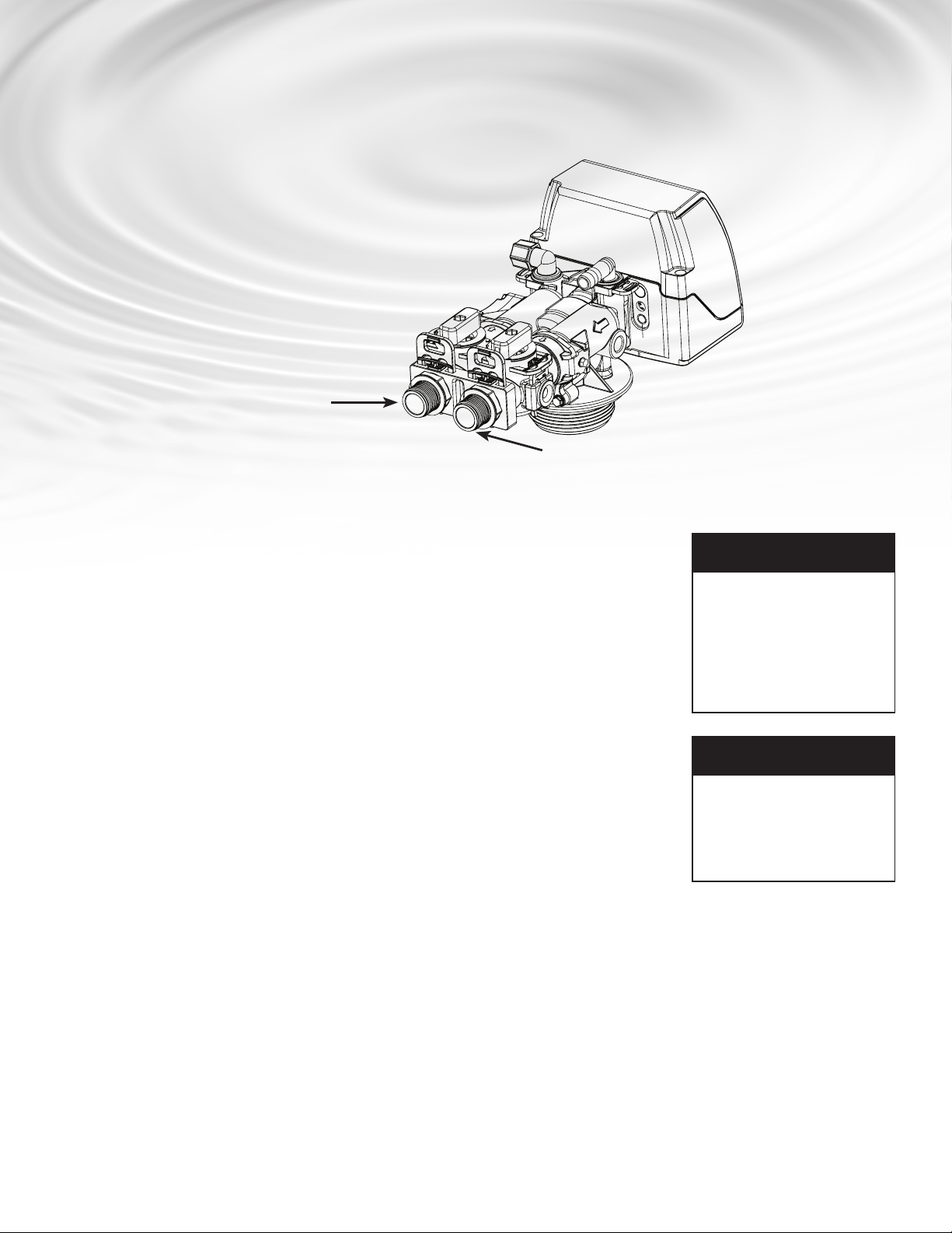
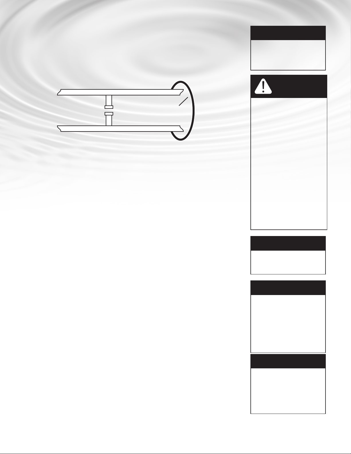
*URXQG6WUDS5HTXLUHG%HFDXVH
RI%UHDNLQ&RQWLQXLW\
)LOWHUHG:DWHU/LQHLQ+RPH
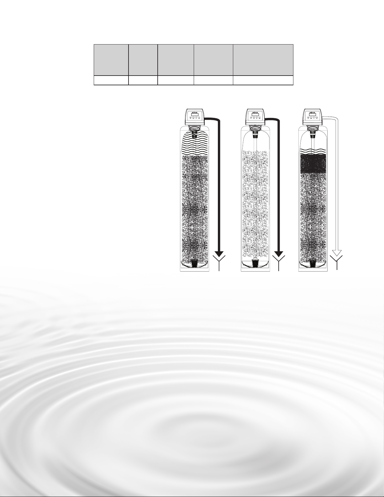
Fig. 1.
BEFORE INSTALLATION NOTE
All government codes and
regulations governing the
installation of these devices
must be observed.
NOTE
If a severe loss in water pres-
sure is observed when the
conditioner unit is initially
placed in service, the condi-
tioner tank may have been
laid on its side during tran-
sit. If this occurs, backwash
the conditioner to
“reclassify” the media.
*NOTE
Due to transportation
and climatic conditions all
connections including the
valve to the tank need to be
checked at time of
installation and tightened if
necessary.
NOTE
Check your local electrical
code for the correct clamp
and cable size.
CAUTION!
If the ground from the
electrical panel or breaker
box to the water meter or
underground copper pipe
is tied to the copper water
lines and these lines are cut
during installation of the No-
ryl bypass valve and/or poly
pipe, an approved grounding
strap must be used between
the two lines that have been
cut in order to maintain
continuity. The length of the
grounding strap will depend
upon the number of units
being installed and/or the
amount of copper pipe being
replaced with plastic pipe.
See Fig. 1.
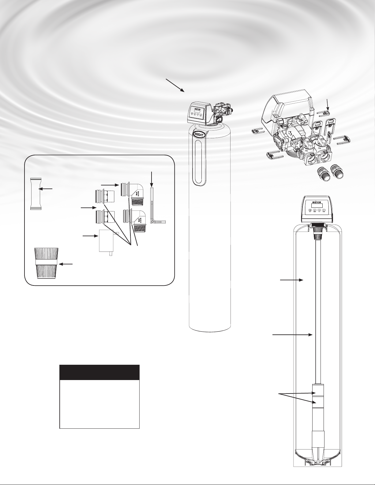
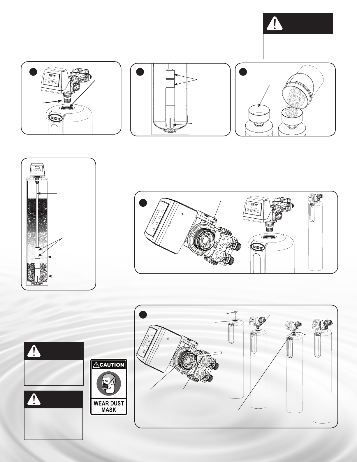
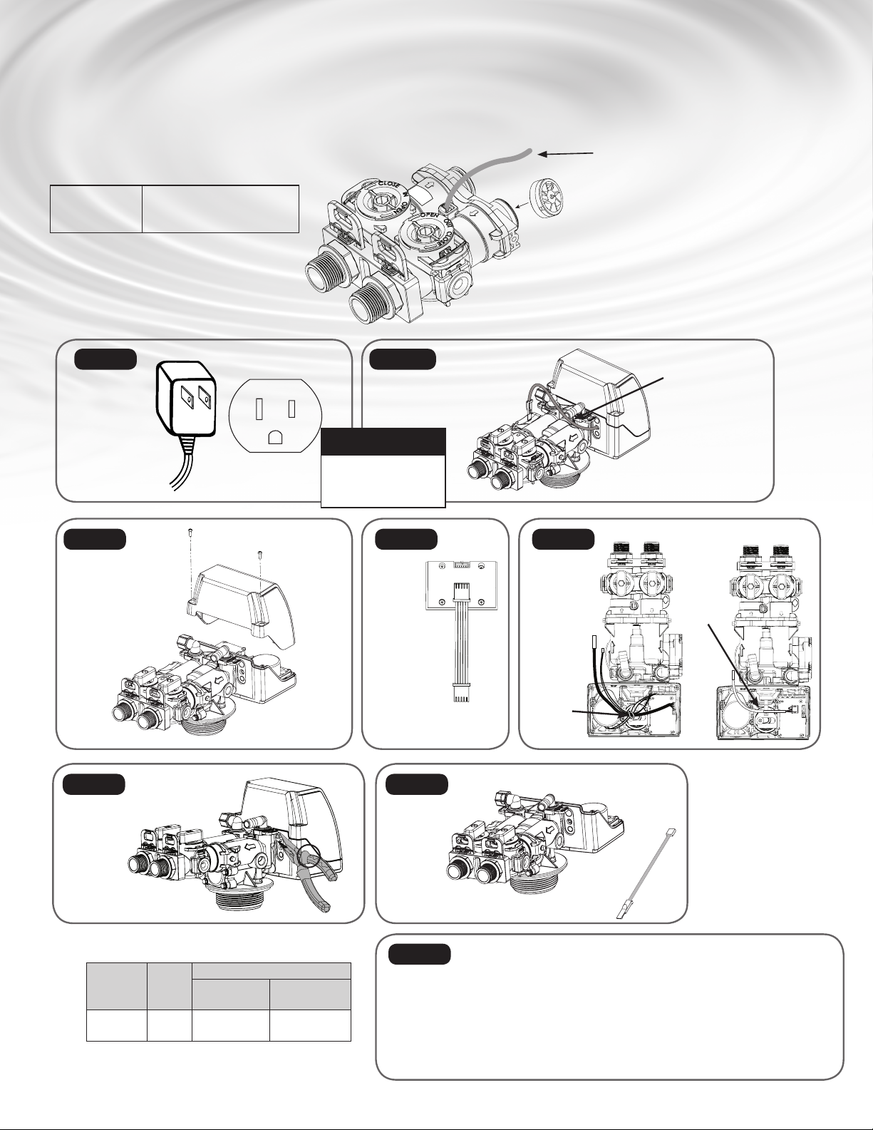
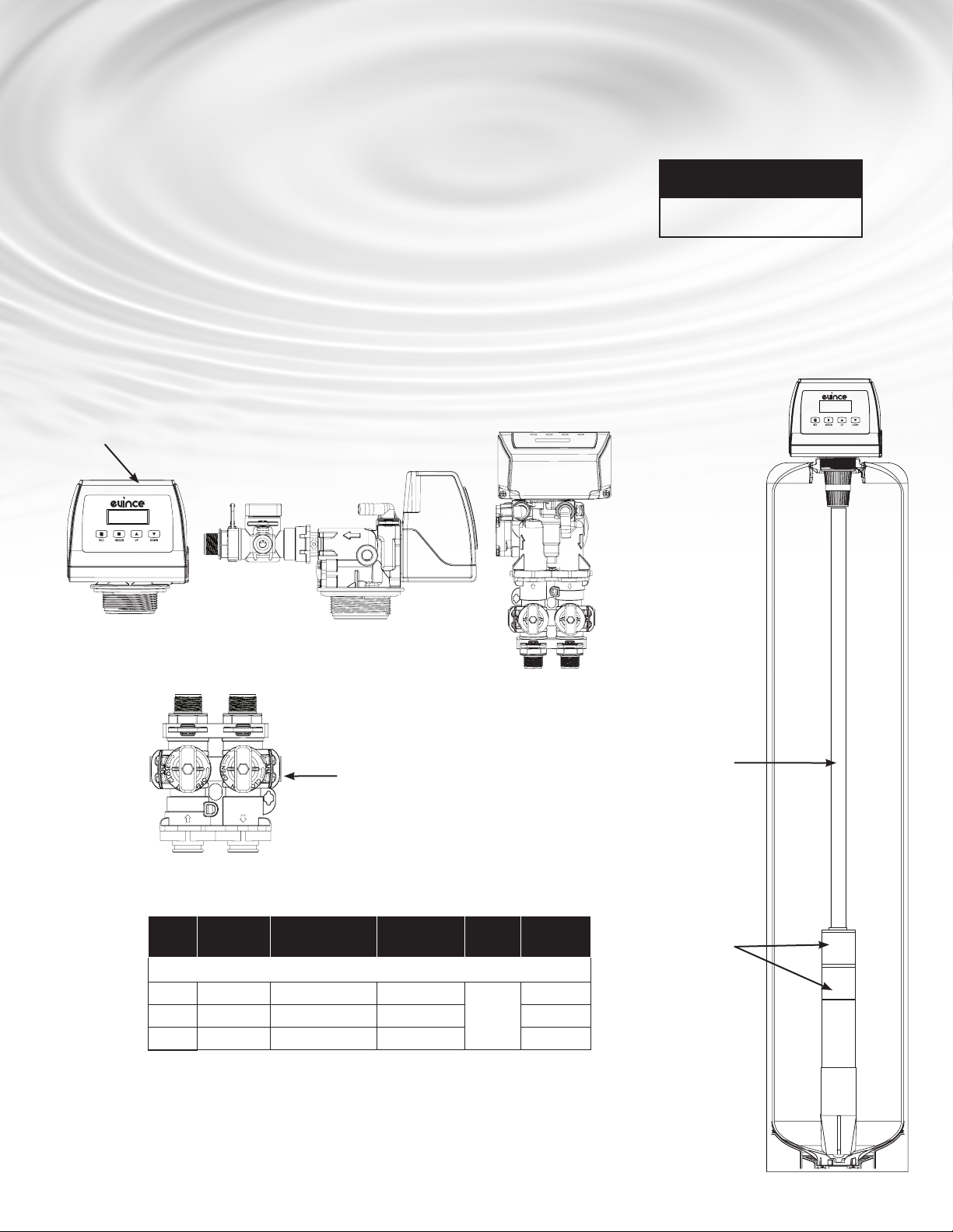
Inspecting and Handling Your Evince Insight Conditioner*
Inspect the equipment for any shipping damage. If damaged, notify the transportation company and request a damage
inspection. Damage to cartons should also be noted.
Handle the conditioner unit with care. Damage can result if it is dropped or set on sharp, uneven projections on the floor.
Do not turn the conditioner unit upside down.
To Ensure this Product Functions Properly:
Your feed water line size to the unit must be a minimum of 1/2 inch with an operating pressure of no less than 30
psi and no more than 125 psi.
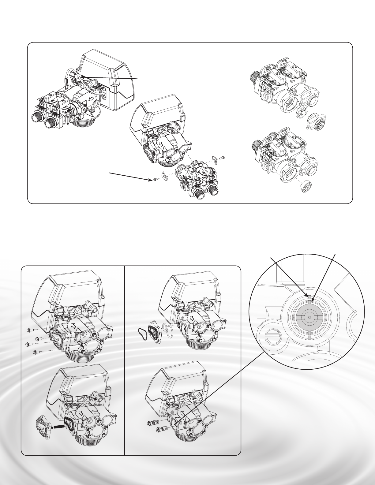
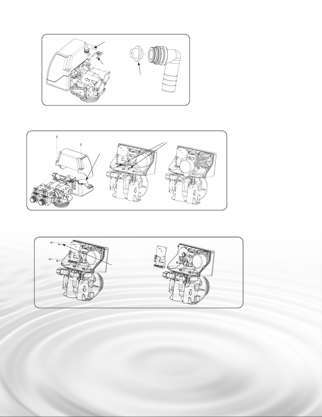
MECHANICAL:
Do not use petroleum based lubricants such as petroleum jelly, oils or hydrocarbon based lubricants.Use only 100% silicone
lubricants (grease packet provided in parts kit). All plastic connections should be hand tightened only. Teflon tape may be used
on connections that do not use an O-ring seal. Do not use pliers or pipe wrenches except where indicated by Nut shape (eg. pipe
adapters) All plumbing must be completed according to local codes. Soldering connections should be done before connecting
any pieces to the pipe as excessive heat can damage them.
Tools Required for Installation:
NOTE: We recommend installation only be completed by a competent installer or
plumbing professional to insure this product is installed in accordance with local
plumbing codes.
sTwo adjustable wrenches
sAdditional tools may be required if modification to home plumbing is required.
sPlastic inlet and outlet fittings are included with the conditioner. To maintain full valve flow, 3/4” or 1” pipes to and from
the conditioner fittings are recommended. You should maintain the same, or larger, pipe size as the water supply pipe, up
to the conditioner inlet and outlet.
sUse copper, brass, or PEX pipe and fittings.
sSome codes may also allow PVC plastic pipe.
sALWAYS install the included bypass valve, or 3 shut-off valves. Bypass valves let you turn off water to the conditioner for
repairs if needed, but still have water in the house pipes.
s5/8” OD drain line is needed for the valve drain. A 10’ length of hose is not included with some models.
Make sure you have a copy of your most recent water test results. If your water has not been tested previously you can contact
your supplier of this product to obtain a water sample bottle to be sent to one of our facilities for a free analysis. In all cases
where metal pipe was originally used and is later interrupted by poly pipe or the Noryl bypass valve or by physical separation,
an approved ground clamp with no less than #6 copper conductor must be used for continuity, to maintain proper metallic pipe
bonding.

89
Fill tank one quarter full of water to protect
distribution during gravel installation.
Place the media into the tank in the order
indicated above. Slowly and carefully add
the gravel support bed and the ltration
media leveling each layer as it is placed into
the tank.
EW-C12 Ultra
Refiner
EW-Clarification d) Unplug the riser tube, carefully position the valve over it and turn the valve into the threads in the berglass tank,
tightening securely into tank. Note: Ensure that the internal O-ring in the valve ts securely over the riser tube.
Silicone grease (part # 92360) or other food grade lubricant may be applied to the O-ring to ease installation of
the riser tube.
d) Lube the bottomValve Orings with the grease supplied, attach the cone. Unscrew the spill cap. Carefully
slide the D-Tube inside the valve and screw the valve inside the tank such that the power cord doesn’t
get caught between the valve and the tank.
O-ring
d
e
CAUTION: Make sure the power cord of the
valve doesnt get caught between the threads
Grease port Orings using
brush (not included) or
your finger (Make sure to
wear protective gloves)
D-Tube
Unscrew Spill Cap Attach EW-Macro Filtration
Plug
the
Riser
Tube
EW-Macro
Filtration
The riser
(EW-Gold Filter
Distributor) remains
inside the tank seated
in the depression at
the bottom
EW-Gold Filter
Distributor
EW-Reliance
EW-Reliance
If required item
number to order a
funnel is 99003
a) Lube the bottom oring (picture d) and attach
the cone to the valve.
b) Temporarily plug the open end of the riser
tube to ensure that no media or gravel falls
down into the distribution. The riser (distrib-
utor) remains inside the tank seated in the
depression at the bottom. Plug tube with a
tape. Remove after media is loaded.
c) Fill support bed first. The media will not
always spill down inside the tank and may
need to be swept inside.The large funnel
(sold separately makes lling the tank easier
and neater. (Or an empty 1 gallon or 4 liter
container with the bottom cut out makes a
good funnel.)
a b c
PREPARATIONS
Media Installation (When Necessary). Models including and higher than 2 CF (Models 200,300) of media are shipped with
separate media in pails or boxes. Models lower than 2 CF of media come loaded with media and this step can be skipped for
new installation.
CAUTION!
The unit should be
depressurized before
installing or replacing media
CAUTION!
Make sure that the
unit is de-pressurized
before conducting
this task.
CAUTION!
DO NOT use petro-
leum based lubricants
as they will cause
swelling of O-ring
seals.

10
NOTE
If the plumbing system is
used as the ground leg of
the electric supply, conti-
nuity should be maintained
by installing ground straps
around any nonconductive
plastic piping used in
installation.
NOTE
Before starting installation,
read page 16, Plumbing
System Clean-Up, for in-
structions on some proce-
dures that may need to be
performed first.
Facts to Remember When Planning Your Installation
1. All installation procedures must conform to local and state or provincial plumbing codes.
2. Make sure the bypass is attached well to the control valve. Connect the straight or elbow connectors to the bypass with black
clips. Connect the inlet and outlet of the water conditioner to the plumbing of the house. The control valve must not be
submitted to temperatures above 43°C (110°F). When sweat ttings are used, to avoid damaging the control valve, solder the
threaded copper adapters to the copper pipe and then, using Teon tape, screw the assembly into the bypass valve.
Do not use pipe thread compound as it may attack the material in the valve body.
3. Apply Teon Tape and Orings to the ttings
4. Connect Conditioner to the house plumbing. Any solder joints near the valve must be done before connecting any piping to the
valve. Always leave at least 6”(152 mm) between the valve and joints when soldering pipes that are connected to the valve.
Failure to do this could cause damage to the valve.
5. Drain Line connection: UsingTeon tape, screw the 1/2”hose barb and attach oring into the drain port in the valve. Attach
1/2”drain hose (Supplied with some models and brands) to the hose barb and tighten securely with a hose clamp (Supplied
with some models and brands). Run the drain line to a oor drain or a laundry drain. Complete any necessary plumbing.
6. Using the Allen Key (included), place the unit in the bypass position. Slowly turn on the main water supply. At the nearest cold
treated water tap nearby remove the faucet screen, open the faucet and let water run a few minutes or until the system is free
of any air or foreign material resulting from the plumbing work.
7. Make sure there are no leaks in the plumbing system before proceeding. Close the water tap when water runs clean.
Determine the best location for your water conditioner, bearing in mind the location of your water supply lines, drain line and 120 volt AC electrical outlet. Subjecting the
conditioner to freezing or temperatures above 43°C (110°F) will void the warranty.
PREPARATIONS
Please notice the inlet and outlet labels on the valve as shown here to
determine the position of the equipment:
Inlet
Outlet

10 11
AC120V/10A
Current Protect Socket
Water Pipe Inlet Water Pipe Outlet
Laundry
Drain
5/8”Clean-Out Line
Optional
Pipes Fixed
Structure
Floor Drain
Water Conditioner Installation
Outlet
Inlet
Cold (Filtered water) Cold (Raw water)
Check Valve
Water Heater
Hot (Filtered Water)
Filter
In
Out
Cold (Filtered Water)
InOut
Connect Conditioner to the HousePlumbing Any solder joints near the valve must be done before connecting any piping to the valve. Always leave at least 6”(152 mm)
between the valve and joints when soldering pipes that are connected to the valve. Failure to do this could cause damage to the valve.
CAUTION!
Never insert drain line
directly into a drain, sewer line, or trap.
Always allow an air gap between the drain
line and the wastewater to prevent the
possibility of sewage being back-siphoned
into the conditioner.
NOTE
Waste connections or drain
outlet shall be designed and
constructed to provide for
connection to the sanitary
waste system through an
air-gap of 2 pipe diameters
or 1 inch (22 mm) whichever
is larger.
WATER CONDITIONER INSTALLATION
*NOTE
Check local plumbing codes
in regards to requirements
for use of Check Valve or
back flow prevention or
vacuum breaker
*
5/8”
Clean-Out
Line
AG100-001
Air Gaps
1 1/2 or 2 inch
standpipe
drain

12
'HVLJQHGDQG(QJLQHHUHGLQ1RUWK
$PHULFD$VVHPEOHGLQ&KLQD
,QMHFWRU
%ODFN
%/)& '/)&
*30
*30
%17+(8)$&9
+9%69%+9
:17
7KLV9DOYHLV7HVWHGDQG&HUWLILHGE\16)
LQWHUQDWLRQDODJDLQVW$16,16)6WDQGDUG
IRUPDWHULDOVDQGVWUXFWXUDOLQWHJULW\
UHTXLUHPHQWVRQO\
1
1
6(77,1*683 '2:1
0$18$/
5(*(1
JAN/01/2017
12:00AM
1. Connect the transformer
to the valve. Plug the
12-volt transformer into
a 120 VAC 60 Hz outlet.
STARTUP INSTRUCTIONS
1. Connect the Transformer to the Valve
Plug the 12-volt transformer into a 120 VAC 60 Hz outlet.
Familiarize with Button Configuration:
The controller will show the following on
the screen - Time, Date and number of Days
Remaining for Regeneration.
2. Screen Display
3. Manually Regenerate the Valve
Manually step the valve to the BACKWASH position. If screen is locked, press SETTINGS Key for 3 seconds to unlock.
Manually Regenerate the Valve and move it to backwash position.
Press MANUAL/REGEN Button for 3 seconds. Press MANUAL/REGEN Button once to select delayed or immediate regeneration. Use Up
and Down Arrows to Select. Press MANUAL/REGEN Key, Press SETTINGS Button to exit and start Regen.
Sample
Connection
Sample
Connection
SERVICE
BYPASS
Sample
Connection
Sample
Connection
SERVICE
BYPASS
MANUAL REGEN
Delay Immediate
BACKWASH
IIIIIIIIIIIIIIIIIIIIIIII 10 Minutes
RINSE
IIIIIIIIIIIIIIIIIIIIIIIIIIIIIIIIIIIIIIIIIIIIIIII 10 Minutes
BACKWASH
RINSE (SKIP)
Key Pad Setting
SETTINGS This function is to enter the basic set up information required at the
time of installation.
MANUAL This function is to initiate an immediate or delayed manual
REGEN regeneration.
DOWN / Increase or decrease the value of the settings while in the
UP programming mode.

12 13
STARTUP INSTRUCTIONS (CONTINUED)
Setting Complete
Press ¨To Return
= Main Menu =
nRegen. Time Setting
nRegen. Days Setting
nAdvanced Menu
= = Regen. Time = =
12:00 AM
Press ¨To Cancel
Press nTo Conrm
Date and Time
Hardness
Manual Regen.
Dealer Information
Main Menu
Setting the Regeneration Time
Press Menu key. Press —to advance to Advanced Menu
Press SET or until you hear a beep
Press +or —to choose menu option. Press SET to enter
Press +or —to change option. Press SET to accept
= = Dealer Information = =
Quality Water
666 3 Ave
Chicago IL
Tel 12345678
Press ¨To Cancel
Press nTo Conrm
Standby Interface
Setting Complete
Press ¨To Return
Date and Time
Manual Regen.
Dealer Information
Main Menu
Date and Time
Manual Regen.
Dealer Information
Main Menu
= = Date andTime = =
17 - Feb - 2016 12:25PM
Press ¨To Cancel
Press nTo Conrm
Setting Time of Day and Dealer Information
Press Menu key
Press SET or until you hear a beep
Press +or —to choose menu option. Press SET to enter
Press +or —to change value. Press SET to accept
3a. (CARBON UNITS – Model TO) Open the inlet on the bypass valve slightly and very slowly allow water to enter the unit. (If the water enters too quickly it will push the
media or carbon up into the control valve and get plugged).
Once the unit has lled suciently that water is at least equal to the height of the top of the media shut down the water for 15 – 20 minutes for the carbon to soak. Unplug the
power cable. After the carbon has soaked for the recommended time continue by plugging the power cable back in.
3b. (Other Models) Open the inlet on the bypass valve slowly and allow water to enter the unit. (The outlet of the bypass should remain closed to prevent any nes or debris
from entering the plumbing system. Allow all air to escape from the unit before turning the water on fully then allow water to run to drain for 3-4 minutes.
4. Unplug the power cord from the power supply, open inlet. Check the drain line ow. Allow the water to run for 30 minutes.
5. Plug in the valve and the valve will automatically advance to the SERVICE position. Open the outlet valve on the bypass, then slowly open the nearest treated water faucet
and allow the water to run until clear, close the tap and replace the faucet screen.
6.TheValve is already programmed from factory for AIO Models. Please set up date and time of day as shown on next page.
Set Up Current Time of Day and Regeneration Time When
Filter Should Regenerate When No one uses Water in House.
Press SETTINGS Key and Select“Date and Time”using MANUAL REGEN
button and set For setting the regeneration time, Press SETTINGS Key
and Select Main Menu till you hear a beep and select Regen time

14
Care of Your Filter
To retain the attractive appearance of your new water lter, clean occasionally with a mild soap solution. Do
not use abrasive cleaners, ammonia or solvents. Never subject your lter to freezing or to temperatures above
43°C (110°F).
Servicing Components
The seals and cartridge should be inspected/cleaned or replaced periodically depending on the inlet water
quality and water usage.
The media should be replenished or replaced depending of inlet water quality and water consumption.
Check with your water treatment expert on the media bed change frequency.
Below are some guidelines:
Please refer to the servicing section of this manual for step by step procedure.
Not following the above will void all warranty on the control valve.
Maintenance of your new water lter requires very little time or eort but it is essential. Regular maintenance
will ensure many years of ecient and trouble free operation.
MAINTENANCE INSTRUCTIONS

14 15
CAUTION!
Disassembly while under
pressure can result in
flooding. Always follow
these steps prior to
servicing the valve.
WARNING!
ELECTRICAL SHOCK
HAZARD! UNPLUG THE UNIT
BEFORE REMOVING THE
COVER OR ACCESSING ANY
INTERNAL CONTROL PARTS
IMPORTANT WARRANTY AND MAINTENANCE INFORMATION
Model number:
Serial number:
Valve Serial number:
Date installed:
Please have the information below lled out and available when calling in for parts or warranty:
Additional notes:
___________________________________________________________________
___________________________________________________________________
___________________________________________________________________
___________________________________________________________________
___________________________________________________________________
___________________________________________________________________
Before Servicing
1. Turn o water supply to conditioner :
a. If the conditioner installation has a 3 valve bypass system rst open the valve in the bypass line, then close the valves at the conditioner inlet & outlet.
b. If the conditioner has an integral bypass valve, put it in the bypass position.
c. If there is only a shut-o valve near the conditioner inlet, close it.
2. Relieve water pressure in the conditioner by stepping the control into the backwash position momentarily. Return the control to the In Service position.
3. Unplug Electrical Cord from outlet.
4. Disconnect drain line connection.
SERVICING EVINCE INSIGHT VALVE

16
Meter Cable
1. Disconnect the meter cable from the meter. (If ow
meter is attached)
2. Remove the front cover of the valve. 3. Remove the piston screw and washer from the piston
rod.
4. Remove the two screws from the powerhead as shown
5. Lift the powerhead from the valve body assembly
6. Replace the powerhead by reverse following the steps in this section
Piston Screw & Washer
Powerhead
Assembly
Valve Body
Assembly
1. Follow steps 1 to 6 of timer /Powerhead
replacement.
2. Remove three screws from the plate on the
valve body.
3. Remove the plate from the valve body and pull the
Piston Assembly from the valve. The brine valve
assembly can also be removed in this stage.
4. Remove the seal spacer assembly, grease it
with silicone lubricant and put back in.
5. Replace piston assembly followed by timer assembly.
6. Replace the piston assembly and reverse
following steps in this section
Remove 3 X
Screws
Plate
Seal and
Spacer
Brine Valve
Assembly
Piston
Assembly
2 X Screws from Powerhead
Front Cover
TIMER REPLACEMENT
PISTON AND/OR BRINE VALVE ASSEMBLY REPLACEMENT

16 17
Meter Cable
1.
3.
4.
2.
2X Clips & Screws
1.
2.
3.
4.
Groove Prominence
METER ASSEMBLY REPLACEMENT
1. Disconnect the meter cable from the meter.
2. Disconnect the valve from bypass by removing clips
3. Remove the coupling adapter from the valve
4. Remove the meter support and then the impeller out from
the coupling and clean it
5. Replace meter with the help of special tool and re-assemble
the removed components back in the section
CLEAN INJECTOR ASSEMBLY
1. Remove four screws of the injector cap.
2. Pull the Injector Cap Out
3. Remove the injector assembly, oring and screen,
4. Clean the injectors and replace cap
PLEASE NOTE: Make sure the two prominences
on the injector are aligned to the grooves
on the valve body.

18
Step 1 Step 2*
Unplug the
power from the
wall socket.
Remove 2 screws and
clips from bypass.
Disconnect the
meter cable from
the bypass.
Grey Meter Cable
60010267
Step 3
Remove Cover.
Step 4 Step 5
Step 6 Step 7
Disconnect
the cables
from the
front PCB
display.
Disconnect
the cables
from the rear
PCB display.
Remove
strain relief
with pliers.
Replace the
old cable
with the
new Cable.
60095101 Bypass comes with Meter
and Grey Meter Cable
*NOTE
Water to the household
needs to be turned off
and pressure relieved
before Step 2
If there are“TB-L” and“TB-H” meter type options in PCB programming, select
“TB-H”.
If the valve programming has no “TB-L” and “TB-H” options, change the meter
ratio to the new value as per chart on left*:
Press the SET to step through to PROGRAMING COMPLETE and past this until
TIME OF DAY screen appears.
Step 8
Assemble the valve.
Plug the power
supply back into
the wall socket
and follow the
programming
shown on right:
Cut the tie
that fastens
the wires
Remove
the meter
cable
attached
on Main
PCB.
If valve is manufactured before March 20th, 2018, and customer wishes to replace or service impeller on bypass. Customer can order 60010238. If customer wishes
to replace to new design, then follow the steps below.
REPLACING THE BYPASS AND METER CABLE
*Meter and Cable Ratio
Valve Model Region
Meter Ratio
(OLD) Before
March 20th 2018
(NEW) After
March 20th 2018
Evince Insight
Series
U.S Gallon 8.000 5.680

18 19
Clip
Drain Line
Elbow
Drain washer
Remove PCBs
by removing the
screws shown in
the picture
1. 2.
Motor Screws
Motor
2.1.
1. Pull the drain line clip and remove the drain line
elbow and washer
2. Clean/replace drain line washer
REPLACE DRAIN LINE FLOW CONTROL
REPLACE MOTOR
1. Remove the powerhead front cover
2. Remove the motor screws and pull
the motor out from powerhead
REPLACING PCBS

20
Control Valve - 10010089
Bypass - 60095101
Model Mineral Tank
Size
Tank # EW-Gold Filter# Valve # Media Bed #
Conditioner Upow (Single Tank)
100 9 x 48 25020052 50010006
10010089
95601
150 10 x 54 25020053 50010005 95606
200 12 x 52 25010058 50010005 95609
EW-Reliance
EW-Gold Filter
Distributor
AFTER SERVICING
1.Reconnect drain line
2. Return bypass or inlet valve to normal in service position. Water Pressure will automatically build in the Conditioner
3. Check for leaks at all sealed areas. Check Drain seal with the control in the backwash position
4. Plug electrical cord into outlet
5. Set Time of Day and cycle the control valve manually to assure proper function. Make sure control valve is returned to the In Service position.
Unit should always be manually regenerated after servicing.
PARTS BREAKDOWN
NOTE
Be sure to shut off any
bypass line.
This manual suits for next models
2
Table of contents
Other Evince Water Filtration System manuals
Popular Water Filtration System manuals by other brands

3M
3M CS-451 Installation and instruction manual

GE
GE SmartWater UCKIT installation instructions

PREMIER WATER SYSTEMS
PREMIER WATER SYSTEMS 600 GPD Instruction & owner's manual

Pentair
Pentair FLECK 5810 SXT Installer manual

Kinetico
Kinetico S Series owner's manual

Thermador
Thermador CHFILT3036 installation manual