Evince INSIGHT EV-IN-BW-948-1.0 User manual

Owners Manual
1. Page 18 of this manual contains important maintenance procedures for the continued proper
operation of your unit. These MUST be performed regularly for your warranty to remain valid.
2. Read all instructions carefully before operation.
3. Avoid pinched o-rings during installation by applying NSF certied lubricant to all seals (provided with install kit).
4. This system is not intended for treating water that is microbiologically unsafe or of unknown quality without
adequate disinfection before or after the system.
Evince™ Direct Phone Number: 951.734.7400
108 Business Center Dr
Corona, CA 92880


Table of Contents
READ THIS PAGE FIRST 5
SPECIFICATIONS 6
WATER AND TIME CONSUMED DURING REGENERATION 7
CONTROL VALVE REGENERATION SEQUENCE 7
UNPACKING / INSPECTION 8
FIND AND RECORD VALVE TYPE & SERIAL NUMBERS
/ RECORDS & CONTACTS 9
BEFORE INSTALLATION 10
PREPARATIONS 11
INSTALLATION STEPS 12
INSTALLATION 13
STARTUP INSTRUCTIONS 15
DURING REGENERATION 16
PLUMBING SYSTEM CLEANUP 17
SYSTEM MAINTENANCE 18
SERVICING EVINCE INSIGHT VALVE 18
DIAGNOSTIC SCREEN 21
REPLACE PISTON AND/OR BRINE VALVE ASSEMBLY 22
CLEAN INJECTOR ASSEMBLY 22
REPLACE TIMER 23
REPLACE MOTOR 23
REPLACING THE BYPASS AND METER CABLE 24
DISPLAY REPLACEMENT 25
REPLACE MICROSWITCHES 25
REPLACE DRAIN LINE FLOW CONTROL 26
REPLACE BRINE LINE FLOW CONTROL 26
AFTER SERVICING 26
PARTS BREAKDOWN 27
TROUBLE SHOOTING GUIDE 30
WARRANTY 32

5
Read this manual thoroughly to become familiar with the
device and its capabilities before installing or operating your
Water Conditioner. Failure to follow instructions in this
manual could result in personal injury or property damage.
This manual will also help you to get the most out of your
conditioner.
This system is intended for use on municipal water only and
its installation must comply with all State, provincial or local
regulations. Check with your local public works department
for plumbing and sanitation codes. In the event the codes
conflict with any content in this manual the local codes
should be followed. Consult your licensed plumber for
installation of this system.
This water conditioner is designed to operate on pressures of
30 psi to 125 psi. If the water pressure is higher than the
maximum use a pressure reducing valve in the water supply
line to the conditioner.
This unit is capable of operating at temperatures between
40°F and 110°F (4°C - 43°C). Do not use this water conditioner
on hot water supplies.
Do not install this unit where it may be exposed to wet
weather, direct sunlight, or temperatures outside of the
range specified above.
Avoid pinched o-rings during installation by applying
(provided with install kit) NSF certified lubricant to all seals.
It is not uncommon for sediment, precipitated iron or
hardness to be present in water supplies. Precipitated
minerals or sediments can cause damage to the seals and
piston. This is considered a harsh environment and the seals
and piston would not be covered by warranty stated or
otherwise.
It is recommended to regularly inspect and service the
control valve on an annual basis. Cleaning and or replacement
of piston, seals, and or spacers may be necessary depending
on how harsh the conditions are. An Annual Maintenance kit
(Part # 60010565) is available for this purpose
Do not use water that is microbiologically unsafe without
adequate disinfection before or after this system.
This publication is based on information available when
approved for printing. Continuing design refinement could
cause changes that may not be included in this publication.
The manufacturer reserves the right to change the
specifications referred to in this literature at any time,
without prior notice.
READ THIS PAGE FIRST
BEFORE STARTING INSTALLATION
INSTALL NOTES &
SAFETY MESSAGES
Watch for the following
messages in this manual:
NOTE
Do not remove or destroy
the serial number. It must be
referenced on request
for warranty repair or
replacement
CAUTION!
Disassembly while
under pressure can
result in flooding.
WARNING!
ELECTRICAL SHOCK
HAZARD! UNPLUG THE UNIT
BEFORE REMOVING THE
COVER OR ACCESSING ANY
INTERNAL CONTROL PARTS
NOTE: used to emphasize
installation, operation or
maintenance information
which is important but does
not present a hazard.
CAUTION: used when
failure to follow directions
could result in damage to
equipment or property.
WARNING: used to
indicate a hazard which
could cause injury or death if
ignored.

6
V-ELA-TT-
SPECIFICATIONS
All units are factory programmed to the below specifications. Alteration should only be done by a factory trained technician or after consultation
with one of our technical representatives if you have any questions please contact:
Evince™ Direct Phone Number: 951.734.7400
Evince Filters
Models Media Cu Ft Flow Rate USGPM Mineral Tank
Size Pipe Size Inches Ship Weight Lbs
Service Peak
EV-IN-BW-948-1.0 1.00 5.0 7.0 9 x 48 3/4”- 1.25” 60
EV-IN-BW-1054-1.0 1.50 7.0 10.0 10 x 54 3/4”- 1.25” 78
EV-IN-BW-1252-1.0 2.00 10.0 12.0 12 x 52 3/4”- 1.25” 95
EV-IN-BW-1354-1.0 2.50 12.0 15.0 13 X 54 3/4”- 1.25” 125
SYSTEM DIMENSIONS
Models A (Inches) B (Inches) C (Inches)
EV-IN-BW-948-1.0 58" 9" 13”
EV-IN-BW-1054-1.0 64" 10" 13”
EV-IN-BW-1252-1.0 62" 12" 13”
EV-IN-BW-1354-1.0 64" 12" 13”
A
B
C
Working Temperature: This unit must be
operated at temperatures between 40°F and
110°F (4°C - 43°C).
Working Pressure: This water refiner must
be operated on pressures
between 30 psi to 125 psi. If the water pres-
sure is higher than 125 PSI, use a pressure
reducing valve in the water supply line to
the refiner.
Voltage = 120V / 60 Hz
Pipe Size = 3/4”, 1” and 1.25"
• At the stated service flow rates, the pres-
sure drop through these devices will not
exceed 15 psig.
• The manufacturer reserves the right to
make product improvements which may
deviate from the specifications and descrip-
tions stated herein, without obligation to
change previously manufactured products
or to note the change.
* Do not use water that is microbiologically
unsafe without adequate disinfection
before or after the system.
Peak flow rates intended for intermittent
use only (10 minutes or less) and are for resi-
dential applications only. Do not use peak
flow rate for commercial applications or for a
continuous rate when treated water supplies
are geothermal heat pump, swimming pool,
etc.
For satisfactory operation, the pumping rate
of the well system must equal or exceed
indicated backwash flow rate.
All units come with plastic bypass
Note: Evince Systems can be installed into homes and small commercial applications with up to 1.25" plumbing. Optional 1.25" connections
available upon request.

67
V-ELA-TT-
CONTROL VALVE
REGENERATION
SEQUENCE
The regeneration cycle goes through 3 steps.
1. Backwash (minimum 30 psi inlet
pressure required): During the backwash
cycle, water ows upwards through the bed,
expanding the media and carrying any
contaminants trapped within it to the drain.
2. Rapid Rinse: During the rapid rinse cycle,
water ows downwards through the bed, settling
the media and carrying any precipitated
contaminants trapped within it to the drain.
3. In-Service Position: The unit then returns
to the In-Service position.While this happens water
continues to enter the tank.
Models Backwash
Minutes
Rapid Rinse
Minutes
Total
Time of
Regeneration
Total Water Consumed during
Regeneration (GAL)
150 10 10 20 100
WATER AND TIME CONSUMED DURING REGENERATION
Step1 Step 2Step 3

8
1. Control Valve
2. Pressure Tank
Bypass with 4
black clips
3. Parts Box
2X 1”
Straight
Adapter
Bypass Tool
2 X 1”
Elbow
Adapter
Transformer
Grease
Packet
2 x Clips
UNPACKING / INSPECTION
Be sure to check the entire unit for any shipping damage or parts loss. Also note damage to the shipping cartons. Contact the transportation
company for all damage and loss claims. The manufacturer is not responsible for damages in transit.
Small parts, needed to install the Conditioner, are in a parts box. To avoid loss of the small parts, keep them in the parts bag until you are ready to
use them.
Models: EV-IN-BW-948-1.0, EV-IN-BW-1054-1.0, EV-IN-BW-1252-1.0, EV-IN-BW-1354-1.0
What is included in the box?
1. Control Valve
2. Pressure Tank
3. Parts Box
4. Owners Manual
5. Drain Hose & Clamp

89
There are two labels located on your Unit: 1) Control valve label and 2) System number label. Find and record your product model number, serial
number, and valve serial number in the Records & Contacts section as they will be important if you need to troubleshoot.
FIND AND RECORD VALVE TYPE & SERIAL NUMBERS
RECORDS & CONTACTS
Model number:
Serial number:
Valve Serial number:
Date installed:
Please have the information below lled out and available when calling in for parts or warranty:
Additional notes:
___________________________________________________________________
___________________________________________________________________
___________________________________________________________________
___________________________________________________________________
___________________________________________________________________
___________________________________________________________________
%17;;;+(8)$&9
+9%69%+9
:17
7KLV9DOYHLV7HVWHGDQG&HUWLILHGE\16)
LQWHUQDWLRQDODJDLQVW$16,16)6WDQGDUG
IRUPDWHULDOVDQGVWUXFWXUDOLQWHJULW\
UHTXLUHPHQWVRQO\
1
;;;;;;;;
;;;;;;;;;;;;
6HULDO1R
Control Valve Serial # System Serial #
Model #
Item #

10
8QILOWHUHG:DWHU%\SDVV
/RRS&XW&DSSHG
*URXQG6WUDS5HTXLUHG%HFDXVH
RI%UHDNLQ&RQWLQXLW\
)LOWHUHG:DWHU/LQHLQ+RPH
Fig. 1.
BEFORE INSTALLATION NOTE
All government codes and
regulations governing the
installation of these devices
must be observed.
NOTE
If a severe loss in water pres-
sure is observed when the
conditioner unit is initially
placed in service, the condi-
tioner tank may have been
laid on its side during tran-
sit. If this occurs, backwash
the conditioner to“reclassi-
fy” the media.
*NOTE
Due to transportation
and climatic conditions all
connections including the
valve to the tank need to be
checked at time of
installation and tightened if
necessary.
NOTE
Check your local electrical
code for the correct clamp
and cable size.
CAUTION!
If the ground from the
electrical panel or breaker
box to the water meter or
underground copper pipe
is tied to the copper water
lines and these lines are cut
during installation of the No-
ryl bypass valve and/or poly
pipe, an approved grounding
strap must be used between
the two lines that have been
cut in order to maintain
continuity. The length of the
grounding strap will depend
upon the number of units
being installed and/or the
amount of copper pipe being
replaced with plastic pipe.
See Fig. 1.
Inspecting and Handling Your EV-IN-BW Conditioner*
Inspect the equipment for any shipping damage. If damaged, notify the transportation company and request a damage
inspection. Damage to cartons should also be noted.
Handle the conditioner unit with care. Damage can result if it is dropped or set on sharp, uneven projections on the floor.
Do not turn the conditioner unit upside down.
To Ensure this Product Functions Properly:
Your feed water line size to the unit must be a minimum of 1/2 inch with an operating pressure of no less than 30
psi and no more than 125 psi.
MECHANICAL:
Do not use petroleum based lubricants such as petroleum jelly, oils or hydrocarbon based lubricants.Use only 100% silicone
lubricants (grease packet provided in parts kit). All plastic connections should be hand tightened only. Teflon tape may be used
on connections that do not use an O-ring seal. Do not use pliers or pipe wrenches except where indicated by Nut shape (eg. pipe
adapters) All plumbing must be completed according to local codes. Soldering connections should be done before connecting
any pieces to the pipe as excessive heat can damage them.
Tools Required for Installation:
NOTE: We recommend installation only be completed by a competent installer or
plumbing professional to insure this product is installed in accordance with local
plumbing codes.
sTwo adjustable wrenches
sAdditional tools may be required if modification to home plumbing is required.
sPlastic inlet and outlet fittings are included with the conditioner. To maintain full valve flow, 3/4” or 1” pipes to and from
the conditioner fittings are recommended. You should maintain the same, or larger, pipe size as the water supply pipe, up
to the conditioner inlet and outlet.
sUse copper, brass, or PEX pipe and fittings.
sSome codes may also allow PVC plastic pipe.
sALWAYS install the included bypass valve, or 3 shut-off valves. Bypass valves let you turn off water to the conditioner for
repairs if needed, but still have water in the house pipes.
s5/8” OD drain line is needed for the valve drain. A 10’ length of hose is not included with some models.
Make sure you have a copy of your most recent water test results. If your water has not been tested previously you can contact
your supplier of this product to obtain a water sample bottle to be sent to one of our facilities for a free analysis. It is important
that this product not be installed until you have this information.
In all cases where metal pipe was originally used and is later interrupted by poly pipe or the Noryl bypass valve or by physical
separation, an approved ground clamp with no less than #6 copper conductor must be used for continuity, to maintain proper
metallic pipe bonding.

10 11
Plug the Riser
Tube
a b
Make sure both brass
and plastic nuts are
tightened well
PREPARATIONS
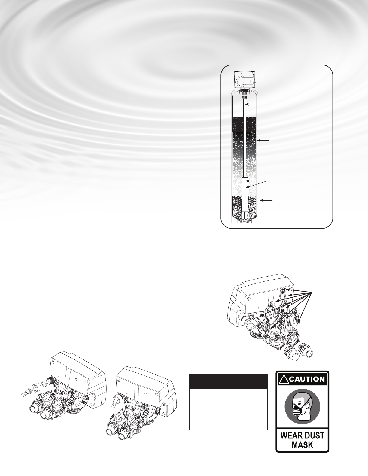
1. Media Installation (When Necessary). Models larger than 2.0 CF of media are shipped with separate media in pails or
boxes. Models lower than 1.5 CF of media come loaded with media and this step can be skipped for new installation.
a) Temporarily plug the open end of the riser tube to ensure
that no resin or gravel falls down into the distribution. The
riser (distributor) remains inside the tank seated in the
depression at the bottom.
Plug tube with a tape. Remove after media is loaded.
5) Fill support bed first. The media
will not always spill down inside
the tank and may need to be swept
inside.
The large funnel (sold separately
makes lling the tank easier and
neater. (Or an empty 1 gallon or 4
liter container with the bottom cut
out makes a good funnel.)
NOTE
The unit is not ready for
service until you complete
the start-up instructions,
page 15.
NOTE
Never make a direct
connection into a waste
drain. A physical air gap of at
least 1.5” should be used
to avoid bacteria and
wastewater travelling back
through the drain
line into the softener.
CAUTION!
The unit should be
depressurized before
installing or replacing media
Locate Water Conditioning Equipment Correctly
Select the location of your filter tank with care. Various conditions which contribute to proper location are as follows:
1. Locate as close as possible to the water supply source.
2. Locate as close as possible to a floor or laundry tub drain.
3. Locate in correct relationship to other water conditioning equipment. if closer than 10 feet please install check valve in
accordance with local plumbing codes.
4. Conditioners should be located in the supply line before the water heater. Temperatures above 110°F (43°C ) will cause
damage to conditioners.
5. Do not install a filter or filter in a location where freezing temperatures occur. Freezing may cause permanent damage to
this type of equipment and will void the factory warranty.
6. Allow sufficient space around the unit for easy servicing.
7. Keep the filter out of direct sunlight. The sun’’s heat may soften and distort plastic parts.
The riser
(NW-Gold Filter
Distributor) remains
inside the tank seated
in the depression at
the bottom
NW-Reliance

12
Inlet
Outlet
NOTE
If the plumbing system is
used as the ground leg of
the electric supply, conti-
nuity should be maintained
by installing ground straps
around any nonconductive
plastic piping used in
installation.
NOTE
Before starting installation,
read page 16, Plumbing
System Clean-Up, for in-
structions on some proce-
dures that may need to be
performed first.
Facts to Remember When Planning Your Installation
1. All installation procedures must conform to local and state or provincial plumbing codes.
2. Outside faucets used to water lawns and gardens should not supply untreated water, replace untreated water with feed water
to the unit. If necessary to do this please install check valve, see page 14. A new water line is often required to be connected to
supply untreated water to the inlet of the water lter and to the outside faucets.
3. Make sure the bypass is attached well to the control valve. Connect the straight or elbow connectors to the bypass with red
clips. Connect the inlet and outlet of the water lter to the plumbing of the house. The control valve must not be submitted
to temperatures above 43°C (110°F).When sweat ttings are used, to avoid damaging the control valve, solder the threaded
copper adapters to the copper pipe and then, using Teon tape, screw the assembly into the bypass valve.
Do not use pipe thread compound as it may attack the material in the valve body.
4. Apply Teon Tape and Orings to the ttings
5. Connect Filter to the house plumbing. Any solder joints near the valve must be done before connecting any piping to the valve.
Always leave at least 6”(152 mm) between the valve and joints when soldering pipes that are connected to the valve. Failure to
do this could cause damage to the valve.
6. Drain Line connection: UsingTeon tape, screw the 1/2”hose barb and attach oring into the drain port in the valve. Attach
1/2”drain hose (Supplied with some models and brands) to the hose barb and tighten securely with a hose clamp (Supplied
with some models and brands). Run the drain line to a oor drain or a laundry drain. Complete any necessary plumbing.
7. Using the Allen Key (included), place the unit in the bypass position. Slowly turn on the main water supply. At the nearest cold
treated water tap nearby remove the faucet screen, open the faucet and let water run a few minutes or until the system is free
of any air or foreign material resulting from the plumbing work.
8. Make sure there are no leaks in the plumbing system before proceeding. Close the water tap when water runs clean.
9. Open the brine tank / cabinet salt lid and add water until there is approximately 3”(75 mm) of water in the tank. Do not add
salt to the brine tank at this time.
1. Determine the best location for your water filter, bearing in mind the location of your water supply lines, drain line and 120 volt AC electrical outlet. Subjecting the filter to
freezing or temperatures above 43°C (110°F) will void the warranty.
INSTALLATION STEPS
Please notice the inlet and outlet arrows
on the valve as shown here to determine
the position of the equipment

12 13
INSTALLATION
Water Pipe Inlet Water Pipe Outlet
AC120V/10A
Current Protect Socket
Laundry Drain
Floor Drain
5/8”Clean-Out Line
Optional
Pipes Fixed
Structure
Cold (Filtered water) Cold (Raw water)
Water Heater
Hot (Filtered Water)
Filter
In In Out
Out
Cold (Filtered Water)
T
o Outside Faucet
5/8”
Clean-Out
Line
AG100-001
Air Gaps
1 1/2 or 2 inch
standpipe
drain
14
BW-Reliance
BW-Gold Filter
BW- C12 Ultra Rener
BW-Clarication
INSTALLATION (CONTINUED)
Evince INSIGHT Units
Open the inlet on the bypass valve slightly and very slowly allow water to enter the
unit. (If the water enters too quickly it will push the media up into the control valve
and get plugged).
Once the unit has lled suciently that water is at least equal to the height of the top
of the media shut down the water for 15 – 20 minutes for the media to soak. Unplug
the power cable. After the media has soaked for the recommended time continue by
plugging the power cable back in.
1. (Other Models) Open the inlet on the bypass valve slowly and allow water to enter
the unit. (The outlet of the bypass should remain closed to prevent any nes
or debris from entering the plumbing system. Allow all air to escape from the unit
before turning the water on fully then allow water to run to drain for 3-4 minutes.
2. Unplug the power cord from the power supply, open inlet. Check the drain line
ow. Allow the water to run for 30 minutes.
3. Plug in the valve and the valve will automatically advance to the SERVICE position.
Open the outlet valve on the bypass, then slowly open the nearest treated water
faucet and allow the water to run until clear, close the tap and replace the faucet
screen.
4. The valve is already programmed from the factory. Please set up date and
time of day as shown on next page.
Clips
5. Connect Drain Line:
a) Using plumbers tape, screw the 1/2”hose barb and attach
o-ring into the drain port in the valve.
b) Attach 1/2”drain hose to the hose barb. and tighten securely
with a hose clamp.
c) Run the drain line to a oor drain or a laundry drain.
Complete any necessary plumbing.
NOTE
DO NOT use petroleum
based lubricants. Use only
NSF61 food grade
lubricants. Petroleum based
lubricants will cause
swelling of O -ring seals.

14 15
2. Screen Display
When power is supplied to the
control, the screen will display
“INITIALIZING WAIT PLEASE”
while it finds the service position.
MENU
SET
System initializing
Please wait
Familiarize with Button
Configuration:
MENU
SET
MENU
SET
This function accepts the values if changed and
advance to the next page in the menu
MENU
SET
MENU
SET
These buttons increase or decrease the value
of the settings while in the programming
mode.
This function enters the basic set
up information required at the time of installation.
Key Pad Configuration
MENU
SET
Date and Time
18-Apr-2018 10:35AM
Gal Remain 1400
Flow Rate 3 gpm/min
The controller will show the
following on the screen: Time,
Date and Gallons Remaining for
Regeneration
Power
Connector
STARTUP INSTRUCTIONS
1. Connect the Transformer to the Valve
Plug the 12-volt transformer into a 120 VAC 60 Hz outlet.
Sample
Connection
Sample
Connection
SERVICE
BYPASS
Sample
Connection
Sample
Connection
SERVICE
BYPASS
MANUAL REGEN
DELAY IMMEDIATE
BACKWASH
IIIIIIIIIIIIIIIIIIIIIIII 10
MINUTES
RINSE
IIIIIIIIIIIIIIIIIIIIIIII 10 MINUTES
BACKWASH
RINSE (SKIP)
3. Set Up Current Time of Day and Regeneration Time When Filter Should
Regenerate When No one uses Water in House.
Press MENU Key
MENU
SET
and Select “Date and Time” using SET
MENU
SET
button and set For setting the regeneration
time, Press MENU Key
MENU
SET
and Select Main Menu till you hear a beep and select Regen time.

16
STARTUP INSTRUCTIONS (CONTINUED)
4. set up date and time of day
TheValve is already programmed from factory for refiner models.
Set Up Current Time of Day and RegenerationTimeWhen Refiner Should Regenerate When No one uses
Water in House.Press Menu Key and Select“Date andTime”using“Set” Button and set for
setting the regeneration time, Press Menu Key and Select Main Menu till you hear a beep and select
Regen time.
Automatic Water Bypass
The regeneration cycle can last 20 mins minutes after which ltered water service will be restored. During regeneration, unltered water is
automatically bypassed for use in the household. Hot water should be used as little as possible during this time to prevent unltered water from
lling the water heater. This is why automatic regeneration is set for sometime during the night and manual regenerations should be performed
when little or no water will be used in the household.
Manual Water Bypass
In the case of emergency you can isolate your water rener from the water supply using the bypass valve located at the back of the control. In
normal operation the bypass is open with the on/o knobs in line with the inlet and outlet pipes.
To isolate the rener, simply rotate the knobs clockwise (as indicated by the word BYPASS and arrow) until they lock.You can use your water related
xtures and appliances as the water supply is bypassing the rener. However, the water you use will be untreated.
To resume water service, open bypass valve by rotating the knobs counterclockwise. Please make sure bypass knobs are completely open otherwise
the unltered water could bypass through the valve.
Date and Time
Hardness
Manual Regen.
Dealer Information
Main Menu
= Main Menu =
Regen. Time
Setting
System Capacity
Salt Mode Setting
Advanced Menu
= = Regen. Time = =
02:25AM
Press To Cancel
Press To Confirm
Date and Time
Hardness
Manual Regen.
Dealer Information
Main Menu
NUVIA
108 Business Center Dr
Corona, CA 92880
TEL 951.734.7400
Date and Time
Hardness
Manual Regen.
Dealer Information
Main Menu
=Hardness =
25 GPG
Press To Cancel
Press To Confirm
Dealer
information
input letter
by letter
Date and Time
Hardness
Manual Regen.
Dealer Information
Main Menu
= = Date and Time = =
17-Jan-2019
12:25pm
Press To Cancel
Press To Confirm
Setting Complete
Press To Return
Setting Complete
Press To Return
Setting Complete
Press To Return Setting Complete
Press To Return
Auto On
Set up
Regeneration Time:
Set up Current Time of the
Day and hardness:
DURING REGENERATION
Sample
Connection
Sample
Connection
SERVICE
BYPASS
Sample
Connection
Sample
Connection
SERVICE
BYPASS
BYPASS

16 17
New Sounds
You may notice new sounds as your water conditioner operates.The regeneration cycle lasts approximately 1.5 hours to 3.0 hours depending on the
specic model. During this time, will be able to hear water running intermittently to the drain, depending on proximity of the unit to sleeping area
and time of regeneration.
PLUMBING SYSTEM CLEAN-UP
The following procedures are guidelines only but have proven successful in most instances. Under no circumstances should any procedure outlined
below be followed if contrary to the appliance manufacturer’s instructions. Should there by any questions concerning the advisability of performing
a procedure, it is strongly recommended the manufacturer’s authorized service outlet be consulted prior to performing the procedure.
Water Heater
If the water heater has been exposed to both iron and hardness for a long period of time, replacement of the
heater tank maybe the only practical solution to prevent continued staining originating from this source. After
completing the installation of the conditioner, clean the water heater by following these instructions:
1. Shut o energy supply to water heater and close heater inlet water valve.
2. Drain hot water tank completely. Open inlet water valve allowing heater tank to be relled with iron-free
water. Continue ushing until water runs clear to drain.
3. If, after approximately 30 minutes ushing, water does NOT clear, terminate ushing operation. Rell hot water heater with water and pour
approximately 1/2 gallon of household bleach into top of heater tank. Allow bleach solution to stand in tank for 20 to 30 minutes. Flush tank
Dishwasher
Consult owners’handbook and follow manufacturer’s instructions.
Toilet Flush Tanks
Prior to commencing installation of the conditioner system, pour 4 to 6 ounces of resin mineral cleaner Pro-Rust Out or or other suitable cleaner
such as CLR that contains a mild acid into ush tanks and bowls and let stand.When installation is completed, ush toilets several times with
conditioned water. If stains or deposits return check that lines are connected to treated water. Repeat procedure until clear. again until water is clear
at drain.Turn energy supply on.
NOTE
If water does not clear in
approximately 10 minutes,
water heater should
probably be replaced.
DURING REGENERATION (CONTINUED)

18
SYSTEM MAINTENANCE
Maintenance of your new water filter requires very little time or effort but is essential. Regular maintenance will ensure many years of
efficient and trouble-free operation. Check with your local dealer about setting up a regular maintenance plan.Failure to follow
maintenance instructions and schedule will result in the unit failing to operate properly and void your warranty.
SERVICE SCHEDULE
The seals and spacers along with the piston assembly should be inspected/cleaned or replaced annually or as required
depending on the inlet water quality and water usage. See Inspection and Replacement of Piston Assembly and Seal and Spacer Kit.
The injectors should be cleaned/inspected or replaced annually or as required depending on the water quality and use.
See Clean Injector Assembly.
Your inlet water quality and water consumption will determine how often the media should be replenished or replaced.
Check with your water treatment expert for the media bed change frequency.
CARE OF YOUR SOFTENER
To retain the attractive appearance of your new water filter, occasionally clean it with a mild soap solution. Do NOT use abrasive cleaners, ammonia,
or solvents.
Before Servicing
1. Turn o water supply to conditioner :
a. If the conditioner installation has a 3 valve bypass system rst open the valve in the bypass line, then close the valves at the conditioner inlet & outlet.
b. If the conditioner has an integral bypass valve, put it in the bypass position.
c. If there is only a shut-o valve near the conditioner inlet, close it.
2. Relieve water pressure in the conditioner by stepping the control into the backwash position momentarily. Return the control to the In Service position.
3. Unplug Electrical Cord from outlet.
4. Disconnect drain line connection.
SERVICING EVINCE INSIGHT VALVE
CAUTION!
Disassembly while under
pressure can result in flooding.
Always follow these steps prior
to servicing the valve.
WARNING!
ELECTRICAL SHOCK
HAZARD! UNPLUG THE UNIT
BEFORE REMOVING THE
COVER OR ACCESSING ANY
INTERNAL CONTROL PARTS

18 19
MASTER PROGRAMMING
Below is how the settings are set at factory:
MENU
SET
Flow Rate: 24.5 GPM
18-Apr-2022 10:35AM
Days Remain 03
Key Pad Conguration:
MENU - This function is to enter the basic
set up information required at the time of
installation.
0(18 83 '2:16(75(*(1
SET/REGEN - This function is to accept the
values if changed and advance to the next page
in the menu.
0(18 83 '2:16(75(*(1
UP/DOWN - These buttons are used
to increase or decrease the value of the settings
while in the programming mode.
PRESS ‘+’ AND ‘-’ FOR 8 SECONDS
PRESS MENU KEY
AND SCROLL TO
‘MAIN MENU’. THEN
PRESS ‘SET’ TILL IT
BEEPS
VALVE SETTINGS
MODELS LANGUAGE REGION VALVE METER
RATIO
SALT VS
EFFICIENCY
AUTO
CALCULATION
REGEN.
MODE
BACK WASH
DURATION
RINSE
DURATION
REGEN
TIME
SETTING
REGEN
DAY
SETTING
Injec-
tor
Injector
Color
BLFC
Washer
DLFC
Washer
DLFC
Washer
Code
EV-IN-BW-948-1.0 ENGLISH US GALLONS FILTER 1.364 DONT TOUCH OFF DAYS 10 10 12:00AM 7 DAYS #1 White 0 5.0 4S
EV-IN-BW-1054-1.0 ENGLISH US GALLONS FILTER 1.364 DONT TOUCH OFF DAYS 10 10 12:00AM 7 DAYS #1 White 0 10.0 2
EV-IN-BW-1252-1.0 ENGLISH US GALLONS FILTER 1.364 DONT TOUCH OFF DAYS 10 10 12:00AM 7 DAYS #1 White 0 5.0 4S
EV-IN-BW-1354-1.0 ENGLISH US GALLONS FILTER 1.364 DONT TOUCH OFF DAYS 10 10 12:00AM 7 DAYS #1 White 0 5.0 4S

20
MASTER PROGRAMMING
= Regen. Mode =
Calendar
Meter Immediate
Meter Delay
Meter Override
= Regen. Cycles =
Backwash Duration
Rinse Duration
= = Regen. Day = =
03 Days
Press¨To Cancel
Press To Confirm
= = Dealer Information = =
Evince
108 Business Center Dr
Corona, CA 92880
TEL 951.734.7400Press
To Cancel
Press To Confirm
= Backwash Duration =
10 Minutes
Press¨To Cancel
Press To Confirm
= Rinse Duration =
10 Minutes
Press To Cancel
Press To Confirm
Setting Complete
Press To Return
Setting Complete
Press To Return
Setting Complete
Press¨To Return
Setting Complete
Press¨To Return
Standby
Interface
Setting Complete
Press¨To Return
Setting Complete
Press¨To Return
= Advanced Menu =
Regen. Mode
Regen. Cycles
History Values
= Main Menu =
Regen. Time Setting
Regen. Days Setting
Advanced Menu
= Main Menu =
Regen. Time Setting
Regen. Days Setting
Advanced Menu
Date and Time
Manual Regen.
Dealer Information
Main Menu
Date and Time
Manual Regen.
Dealer Information
Main Menu
= = Regen. Time = =
12:00 AM
Press To Cancel
Press To Confirm
= = Date and Time = =
17 - Feb - 2016
12:25PM
Press To Cancel
Press To Confirm
= Advanced Menu =
Regen. Mode
Regen. Cycles
History Values
= Main Menu =
Regen. Time Setting
System Capacity
Salt Mode Setting
Advanced Menu
Date and Time
Hardness
Manual Regen.
Dealer Information
Main Menu
Main Menu
Regen. Time Setting
Regen. Day Setting
Advanced Menu
= = Initial Setup interface = =
nLanguage
nRegion
nValve
nMeter Ratio
nSalt vs Eciency Setting
nCalculation
= = Initial Setup interface = =
nLanguage
nRegion
nValve
nMeter Ratio
nSalt vs Eciency Setting
nCalculation
= = Initial Setup interface = =
n Language
n Region
n Valve
n Meter Ratio
n Salt vs Eciency Setting
n Calculation
= = Initial Setup interface = =
n Language
n Region
n Valve
n Meter Ratio
n Salt vs Eciency Setting
n Calculation
= = Initial Setup interface = =
n Language
n Region
n Valve
n Meter Ratio
n Salt vs Eciency Setting
n Calculation
= = Initial Setup interface = =
n Language
n Region
n Valve
n Meter Ratio
n Salt vs Eciency Setting
n Calculation
= Language =
nEnglish
= Region =
nU.S. Gallon
= Valve Setting =
nFilter
nDownFlow
nUpFlow
= Salt Vs Eciency =
Don’t Touch
n E: 03.0 lbs Vs 5000 Grs
n S: 06.0 lbs Vs 4150 Grs
n H: 12.0 lbs Vs 2500 Grs
Meter Ratio
1.364
Press ¨To Cancel
Press nTo Conrm
== Auto Calculation ==
ON OFF
Press ¨To Cancel
Press nTo Conrm
Setting Complete
Press ¨T o Return
Setting Complete
Press ¨To Return
Setting Complete
Press ¨To Return
Setting Complete
Press ¨To Return
Setting Complete
Press ¨To Return
Setting Complete
Press ¨To Return
STANDBY INTERFACE
Step B - Advanced Menu
Press Menu key. Press — to advance to Advanced Menu
Press + or — to choose menu option. Press SET to enter
Press + or — to change option. Press SET to accept
Step C - Main Menu
Press Menu key. Press — to advance to Advanced Menu
Press SET or until you hear a beep
Press + or — to choose menu option. Press SET to enter
Press + or — to change option. Press SET to accept
Step D - User Setting
Press Menu key
Press SET or until you hear a beep
Press + or — to choose menu option. Press SET to enter
Press + or — to change value. Press SET to accept
Press Menu key. Press — to advance to Main Menu
Press SET or until you hear a beep.
Press — to advance to Advanced Menu
Press and hold SET 5 seconds or until you hear a beep.
Press + or — to choose menu option. Press SET to enter.
Press + or — to change option. Press SET to accept.
Step A - Region Setting
Press + and —. Hold until you hear a beep (8 seconds).
Press + or — to choose menu option. Press SETTINGS to enter.
Press + or — to change option. Press SETTINGS to accept.
This manual suits for next models
3
Table of contents
Other Evince Water Filtration System manuals


