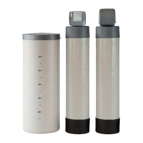
Safeway water 4 Stage Ro Operating and safety instructions

RO
FILTRATION
SYSTEM
4STAGE
Note :
Please read through the instructions carefully before using or installing the product
and ensure that the manual is kept in a safe place for future reference.
The system must be properly installed and located in accordance with the installation
instructions before it is used.

I
Installation & Maintenance Guide

1. Safety Instructions
Attention M9 QUICK CHANGE RO WATER FILTRATION SYSTEM Customer
This system is intended for use on potable water supplies or disinfected water containing cysts. Do not use
where water is microbiologically unsafe or with water of unknown quality. If bacterial contamination is present,
a recognized method of water disinfection is required.
The M9 QUICK CHANGE RO WATER FILTRATION SYSTEM contains a replaceable reverse osmosis membrane
filter which is critical for the effective reduction of Total Dissolved Solids. The filtered water should be tested
periodically to verify that the system is performing properly.
SAFE PRACTICES
Throughout this manual there are paragraphs set off by special headings.
Note : Note is used to emphasize installation, operation or maintenance information which is important, but
does not present any hazard. Example :
Caution is used when failure to follow directions could result in damage to equipment or property. Example :
Warning!: Warning is used to indicate a hazard which could cause injury or death if ignored. Example:
CAUTION! Disassembly while under water pressure can result in flooding.
WARNING! Electrical shock hazard! Unplug the unit before removing the timer mechanism or cover
plates!
Note : The nipple must extend no more than 1 inch above the cover plate.
I
Installation & Maintenance Guide 1

2. Specifications
Sediment
Filter
Purpose
Sediment
Reduction
Chlorine Taste
and Odor
Micron
Rating Capacity
2500 gallons
(9460 liters)
Flow Rate
0.5 gal/min
(1.9 liters/min)
Rated Life Stage
6 Months
Working
Temperature
Range
4-38°C
(40-100°F)
Working
Pressure
Range
30-125 psi
Carbon Block
Filter
5
5
1
2&4
Replacement Filter
RO
Membrane
50 GPD
Purpose
TDS
Reduction
Recovery
(product Water
/ Inlet Water)
TDS
Reduction*
96%
Rating**
50 gallons/day
(189 liters/day)
(No Storage
Tank Attached)
Rated Life Stage
24 Months
Working
Temperature
Range
4-38°C
(40-100°F)
Working
Pressure
Range
(1)
40-125 psi30% 3
* The performance and life of a reverse osmosis membrane or filter element is highly dependent upon pressure, temperature and dissolved solids (TDS)
** Manufacturer's Specification only with inlet conditions of 50 psi, 25℃(77℉), going to atmosphere. The actual volume of product water and rejection percentage will bary
with differences from the test conditions that membrane ratings are based upon
(1) Pressure Regulator is recommended for feed water pressures exceeding 80psi
Stage 1 Stage 2 Stage 3 Stage 4 Storage Tank Faucet
Sediment Filter Activated Carbon Filter Activated Carbon Filter
Reverse Osmosis
Membrane TP-12P NCPV 893
CP-KR01
Daily Production Rate*
76.8(20.3)
Sediment Filter Activated Carbon Prefilter
Reverse Osmosis Membrane Storage Tank
Activated Carbon Postfilter
Dispensing Faucet
5 Micron
Carbon Block 5 Micron
Thin Film Composite
Metal
–
Capacity 3.2 Gallon (12 Liters)
L/day (G/day)
Typical System Flow Sequence
Sediment Filter (Stage 1)
Activated Carbon Prefilter & Postfilter (Stage 2&4)
Reverse Osmosis Membrane (Stage 3)
Storage Capacity
IInstallation & Maintenance Guide 2

Sediment filter 11"
GAC (Granular Activated
Carbon) filter 11"
Carbon block filter 11"
RO membranes filter 11"
GAC (Granular Activated
Carbon) filter 13"
Sediment filter 13"
Carbon block filter 13"
RO membranes filter 13"
Particulate, dirt & sand
Chlorine, taste and odor
Particulate, dirt & sand
hlorine, taste and odor
RO membranes
Chlorine, taste and odor
Particulate, dirt & sand
Chlorine, taste and odor
RO membranes
FILTER CARTRIDGES FUNCTION RATED LIFE CAPACITY
6 months or 12 months
2years
2 years
1,500 Gallons (5,678 Liters)
2,500 Gallons (9,463 Liters)
-
-
-
-
Dimensions
Replacement Cartridge
100mm
Total 548mm
100mm
200mm 200mm
Cupboard Wall
Note : Rated life and Capacity are depending on local water conditions and level of prefilteration.
Note : The disposable filter cartridge must be replaced every 6 months or 12 months, at the rated capacity or
if a noticeable reduction in flow rate occurs
Note : Performance of the reverse osmosis membrane is affected by several factors which must be considered
when judging the condition of the system. The main factors which affect system performance are
pressure, temperature, total dissolved solids level, recoevery and pH.
IInstallation & Maintenance Guide 3

Recommended Influent Water Characteristic Notes
System Pressure
Temperature
pH range
Turbidity
Hardness (CaCO3)
Iron (Fe)
Chlorine (Cl2)
40 - 100 psi (2.8 - 7kgf/cm2)
40 - 100 °F (4 - 38 °C)
5.0 - 10.0
< 10 Net Turbidity (NTU)
< 300 ppm
0 - 1 ppm
0 - 3 ppm (0 - 3 mg/L)
1. The reverse osmosis membrane used in these systems
may be damaged by chlorine. These systems include
activated carbon filters which protect the membranes
by reducing chlorine. Influent chlorine should not
exceed 3 mg/L
2. Additional information on factors that affect RO
performance can be found in the "Performance &
Technical Information" section.
Arsenic Facts
Arsenic (abbreviated As) is found naturally in some well water. Arsenic in water has no color, taste, or odor. It
must be measured by a laboratory test. Public water utilities must have their water tested for arsenic. You can
get the results from your water utility. If you have your own well, you can have the water tested. The local health
department or the state environmental health agency can provide a list of certified labs. The cost is typically
$15 to $30. Information about arsenic in water can be found on the Internet at the U. S. Environmental Protection
Agency website: www.epa.gov/safewater/arsenic.html. There are two forms of arsenic: pentavalent arsenic
(also called As(V), As(+5), and arsenate) and trivalent arsenic (also called As(III), As(+3), and arsenite). In well
water, arsenic may be pentavalent, trivalent, or a combination of both. Special sampling procedures are needed
for a lab to determine what type and how much of each type of arsenic is in the water. Check with the labs in
your area to see if they can provide this type of service. Reverse osmosis (RO) water treatment systems do not
remove trivalent arsenic from water very well. RO systems are very effective at removing pentavalent arsenic.
A free chlorine residual will rapidly convert trivalent arsenic to pentavalent arsenic. Other water treatment
chemicals such as ozone and potassium permanganate will also change trivalent arsenic to pentavalent arsenic.
A combined chlorine residual (also called chloramine) may not convert all the trivalent arsenic. If you get your
water from a public water utility, contact the utility to find out if free chlorine or combined chlorine is used in the
water system. The QCRO4V-50 system is designed to remove pentavalent arsenic. It will not convert trivalent
arsenic to pentavalent arsenic. The system was tested in a lab. Under testing conditions, the system reduced
[0.30 mg/L (ppm) or 0.050 mg/L (ppm)] pentavalent arsenic to 0.010 mg/L (ppm) (the USEPA standard for
drinking water) or less. The performance of the system may be different at your installation. Have the treated
water tested for arsenic to check whether the system is working properly. The RO component of the QCRO4V-50
system must be replaced every three (3) years to ensure that the system will continue to remove pentavalent
arsenic. The component identification and locations where you can purchase the component listed in this
installation/operation manual.
IInstallation & Maintenance Guide 4

3. Installation Instructions
TYPICAL INSTALLATION DIAGRAM
1/4” Angle Stop Adaptor
Valve(ASVPP1)
1/4” Orange Tube
NCPV 893 CP-KR01
1/4” Blue Tube
J.G Tank Shut Off Valve
1/4” White Tube
Pressure Tank TP-12P
1/4” Drain Saddle Valve
1/4” Black Tube
IInstallation & Maintenance Guide 5

Tubing Connectors
Connect :
Cut the tubing squarely with a sharp knife. Be careful not to crush the tubing. To avoid
leaks, make sure the tubing end is smooth and free of burrs and abrasions. Lubricate
the end of the tube with water or a light coat of silicone and push the tube end firmly
into the fitting. You should feel it push past the O-ring. Avoid bending the tubing sharply
away from the fitting.
Disconnect :
Hold the collar against the fitting body and pull the tube from the fitting. In the unlikely
event that the connection leaks, remove and recut the tubing. Check the inside of the
fitting for debris or O-ring damage. Reconnect. Push-to-connect tubing connectors
grip the outside diameter of the tube. To help assure a reliable connection, it is important
to use high quality tubing with a consistent outside diameter.
Quick-Connect Fitting
Insertion & Removal of Plastic or Copper Tubing
1. Simply push in tube to attach. 2. Tube is secured in position. 3. Push in collet from both sides to release tubing.
Cut tube squarely
with a sharp knife.
Step 1 –Select Component Installation Locations
• Dispenser Faucet
–
The faucet is designed to be mounted on the rear lip of the sink. It may be installed in an existing sprayer
attachment hole or in a hole drilled at the time of installation. It may also be mounted to an adjacent counter
top. It should be positioned so that water is dispensed over the sink. A 7/8” diameter hole is required.
• Important considerations
–
Access to the bottom (undersink) of the faucet is required for attachment of product water line.
–
There should be no undersink obstructions which would prevent smooth tubing runs to the drain connection,
or RO module assembly.
• Filter System Assembly
–
The filter system assembly is designed to be mounted on any rigid vertical surface such as a cabinet sidewall,
sheetrock in exposed stud. It should be positioned such that there is access to an inlet water source and drain.
The installation should also allow convenient access for servicing.
• Inlet Water Supply Connection
–
Once a location is chosen for installation of the filter system assembly, select a nearby cold water line to
provide the water source for the system.
• Drain Connection
–
The most convenient entry to the drain is directly above the P-trap of the kitchen sink. However, the drain
water from the system can be connected to adjacent sinks or a floor drain. Extra care should be taken when
entering drains near dishwashers or food waste disposals as back flow may occur through the air gap and
cause flooding.
Note : Follow all local plumbing codes when connecting to drain.
Note : Follow all local plumbing codes when connecting to service water.
IInstallation & Maintenance Guide 6

Step2. Faucet Installation
The M9 QUICK CHANGE RO WATER FILTRATION SYSTEM features reliable and convenient push-to-connect
tubing connectors. Tubing is easily connected and disconnected from these fittings as follows.
To simplify its access and installation, we suggest you install the faucet on the rear lip of the sink. It should be
evenly positioned with the sink faucet and spray attachment. Should the spray faucet hole not be available for
the installation, the sink must be drilled.
Sink Drilling Instructions
Porcelain Enamel Sink
Follow these basic guidelines when drilling a porcelain sink:
Pilot Drill Spring Loaded Porcelain Saw Finish Hole Saw
- Penetrate the porcelain to the base
material.
- Protect the surrounding porcelain
material.
- Use the appropriate tool to drill the
base material.
Stainless Steel Sink
1. Select and mark the
proper faucet location.
2. Center punch hole to
provide a starting point
for your drill.
3. Drill a 7/8” hole in the sink using a stepped 7/8”
drill bit. If no stepped bit is available, start by
drilling a 1/4” hole. Using this hole as a starting
point progressively drill larger holes. Increase
drill size by 1/8” until you reach a 7/8” hole.
Note : It is recommended retaining the services of a professional counter top craft person when a hole is
needed in granite or other specialty counter top materials.
Take length of 1/4” blue tube and make sure it is has a fresh cut and is free
of foreign materials and any scratches on the outside surface. Install the
tubing into the push in type fitting at the base of the faucet. Make certain
that it is inserted all the way in; once inserted give it a slight pull to make
sure it is locked into the fitting.
You have now completed the tubing connections.
Product Line from
M9 RO System
(1/4” Blue Tube)
1/4” Faucet Adapter
Note : To disconnect tubing from the product water fitting, hold the collet
firmly against fitting body and pull the tube from the fitting. Repeated
assembly and disassembly will cause wear to the inner body.
Visually inspect for excessive wear and replace the inner body as
needed to protect against any leaks.
IInstallation & Maintenance Guide 7

Step 3 – Install Adapter Valve on Water Supply(ASVPP1)
Step 4 – Connect System Drain
This connection can usually be made beneath the sink. Incorrect installation may result in overflow of the air
gap or excessive noise. Connections to undersink plumbing can be made with a saddle clamp designed to
accept the drain tubing from the faucet. Drain Saddle Kit is supplied for 1-1/2” undersink drain plumbing. Be
sure to check and follow local plumbing codes prior to installation.
1. Install the drain saddle valve on to the drain pipe. Use 1/4” saddle for drain water line.
2. Tighten the clamps with the help of the two bolts.
3. For the standard faucets drill a 1/4” hole through one side of the pipe. The drill should be kept straight and
centered to avoid damaging the saddle valve. Do not drill through both sides of the pipe!
CAUTION! The Adapter valve should be connected to cold water supply only. Connection to hot water
supply will damage the system and will void all warranty
WARNING! Do not overtighten.
WARNING! Do not drill through both sides of pipe!.
2 3 41
1. Shut off water at supply valve.
Verify the gasket is
properly seated
Cold Water
Line to
Faucet
Cold Water
Supply Valve
4. Connect riser hose to
adapter valve.
5. Insert 1/4” orange tube into
quick connect fitting on valve.
6. Open the cold water supply
valve and check for leaks.
2. Disconnect hose from supply
valve.
3. Install adapter valve on supply
valve.
IInstallation & Maintenance Guide 8

Sink Sink
Disposal
Do not install here
Install here
(1/4” drain saddle valve)
Step 5 – Start-Up
1. Sanitize the storage tank.
2. Check system to verify all components are correctly installed
3. Open inlet valve and tank valve.
4. Check system thoroughly for leaks. If any are found, shut off both inlet and tank valves and correct the issue.
5. Allow system to run & fill tank for 1-2 hours. You will hear the water running to drain while the unit is running.
Once the water stops running to drain the tank is full.
6. Open faucet to flush carbon fines & sanitization solution. Once the flow begins to slow down (around 20
minutes after opening) turn off the faucet.
7. Allow the tank to fill completely again.
8. Once full, open the faucet and allow the water to run for 24 hours to break-in the RO membrane and
completely flush the system. This will allow your system to run at optimal efficiency.
9. Close faucet and allow tank to fill.
10. System is ready to use
4. Attach 1/4” black tube by slipping the tube through the black compression nut and hand tighten the nut on to
the saddle valve.
Many homes are equipped with disposals and
dishwashers. Home drain plumbing must be free of
any blockage since this may cause a backup of
dishwasher and disposal waste into the drain line
and result in improper performance. To perform a
simple drain check, fill the sink basin with several
inches of water, pull the plug, and observe the drainage.
If water backs up into the second sink (if present), or
if drainage is slow or there is excessive gurgling, drain
blockage may be present. Undersink drain plumbing
usually resembles one of the following descriptions.
In all cases, the drain tubing from RO membrane filter should run downward, free of dips and loops. This can
vent sewer gas, which will produce foul odors.
CAUTION! The drill should be kept straight and centered to avoid damaging the saddle valve.
IInstallation & Maintenance Guide 9

Performance & Technical Information
The performance of the M9 RO System can be characterized and judged by the quality and quantity of the water
produced by the system. By measuring the contaminant removal performance and flow rates of the system, its
operating status can be easily evaluated.
Factors Which Affect Performance
Performance of the reverse osmosis membrane is affected by several factors which must be considered when
judging the condition of the system. The main factors which affect system performance are pressure, temperature,
total dissolved solids level, recovery and pH.
Pressure
Water pressure affects both the quantity and quality of the water produced by the RO membrane. Generally, the
more water pressure, the better the performance of the system. Be careful not to go below 40 psi or exceed
100 psi, the minimum and maximum operating pressure of the system.
Temperature
The reverse osmosis process slows with decreasing temperature. To compensate, a temperature correction
factor is used to adjust the actual performance of the RO membrane filter to the standard temperature of
77°F(25°C). This allows the performance of the unit to be accurately gauged against published standards.
Temperature does not affect the concentrate flow rate.
Total Dissolved Solids
The minimum driving force which is necessary to stop or reverse the natural osmosis process is termed osmotic
pressure. As the total dissolved solids level of the feed water increases, the amount of osmotic pressure increases
and acts as back pressure against the reverse osmosis process. Osmotic pressure becomes significant at TDS
levels above 500 mg/L (ppm).
Hardness
Hardness is the most common membrane fouling. If ignored, this relatively harmless component of feed water
will scale a membrane over time. Use of a softener will reduce the fouling effect on a membrane. One way to
detect too much hardness in the feed water is the weight of a membrane installed for a period of time. A fouled
membrane (dried) will weigh significantly more than a new membrane. The increase in weight is a result of
precipitated hardness inside the membrane.
Note : Increased weight of the RO cartridge may be a fouling other than hardness.
IInstallation & Maintenance Guide 10

Troubleshooting Guide
If a problem cannot be corrected through the use of this troubleshooting guide :
• Serial #
• Model #
4. External leakage. a. Tubing not fully seated in fitting a. Check all fittings for tightness.
b. Tubing abraded in seal area. b. Recut tubing and redo connection.
5. Overflow at faucet
air gap (gurgling
sounds).
a. Concentrate tubing plugged. a. Clean concentrate tubing of debris.
b. Concentrate tubing not in continuous
downward slope.
b. Eliminate loops or low spots in tubing.
c. Obstructed home drain pipe. c. Free obstruction.
6. Foaming at faucet tip. a. Storage tank is positioned on side
(Dissolved air cannot escape.)
a. Place tank in vertical position.
7. Foaming at air-gap a. Concentrate tubing connected to same
drain line as dishwasher, etc.
a.Find different drain for system.
b. When sink is full of soapy water and plug
is pulled, can back up at air-gap.
b.Obstructed home drain, free obstruction.
c. Obstructed home drain. c. Free obstruction.
Problem Possible Cause Remedy
1. Insufficient quantity
of product water
available to service.
a. Service greater than unit’s specified output. a. Use optional large tank for more storage
capacity.
b. Insufficient feed water flow. b. 1. Clogged shut-off valve or feed tubing ;
clean out or replace. 2. Clogged prefilter;
replace. 3. Clogged manifold; clean or
replace.
c. Insufficient feed water pressure c. 1. Same as (b) above. 2. Change in line
pressure; install booster pump.
d. Increase in feed water TDS. d. 1. Same as (a) above.
2. Install booster pump.
e. Reduced feed water temperature. e. Same as above.
f. Plugged prefilter. f. Replace filter element.
g. Plugged polishing filter. g. Replace polishing filter.
h. RO membrane fouled with sediment. h. Replace RO membrane and prefilter
elements.
i. Shutoff malfunction. i. Clean or replace shutoff.
2. Poor product water
quality.
a. All of (1) above except (a) and (e). a. All of (1) above except (a), (e), and (g).
b. RO membrane filter worn out. b. Replace RO membrane.
c. Shut off malfunction. c. Replace shut off
3. Bad tasting product
water.
a. Decrease in product quality; see (2) above. a. Same as (2) above.
b. Foreign matter in storage tank. b. Clean, sanitize, and flush storage tank.
c. Polishing filter exhausted. c. Replace polishing filter
d. Plugged capillary tube. d. Replace capillary tube; replace prefilter, if
necessary.
e. Storage tank bladder is ruptured. e. Replace storage tank and check
precharge pressure.
IInstallation & Maintenance Guide 11

Problem Possible Cause Remedy
8. Bad smell from
product water.
a. Polishing filter exhausted. a. Replace polishing filter.
b. Prefilter element. b. Replace filter element.
c. Unit needs disinfection. c. Sanitize unit.
9. Fast flow to drain. a. Defective flow control assembly. a. Replace flow control assembly.
10. Black specks in
product water.
a. Carbon fines. a. Flush polishing filter.
11. Low faucet pressure. a. Inadequate pre-charge pressure in
storage tank.
a. Check tank pre-charge pressure and add
air if required.
b. Polishing filter plugged. b. Replace polishing filter.
12. Flow control plugging. a. Excessive turbidity. a. Install another 5 micron filter in series with
existing one or substitute carbon block
filter for granular activated carbon filter.
b. Iron fouled. b. Pretreat for iron removal.
c. Iron-bacteria fouled. c. Sanitize plumbing.
IInstallation & Maintenance Guide 12

Limited One-year Warranty
Any defect tn materials or workmanship in the manufactured product.
What does this warranty not cover?
1. Improper installation, delivery or maintenance.
2. Failure of the product if it is abused misused, altered, used commercially or used for other than the intended
purpose.
3. Use of this product where water is microbiologically unsafe or of unknown quality, without adequate disinfection
before or after the system.
4. Damage to the product caused by accident, fire, floods or acts of God.
5. Incidental or consequential damage caused by possible defects with this application, it’s installation or repair.
Exclusion of Implied Warranties
Your sole and exclusive remedy is product
exchange as provided in this Limited
Warranty. Any implied warranties, including
the implied warranties, including the implied
warranties of merchantability or fitness for
a particular purpose, are limited to one year
or the shortest period allowed by law.
4. Limited One-year Warranty
IInstallation & Maintenance Guide 13

RO
FILTRATION
SYSTEM
Table of contents
Other Safeway water Water Filtration System manuals
Popular Water Filtration System manuals by other brands

Spirax Sarco
Spirax Sarco 5800 Series Installation and maintenance instructions

KENT
KENT Elegant Lite Mineral RO Instruction handbook

Master Water Conditioning
Master Water Conditioning MBA Series Installation and operation manual

NEO
NEO Spring user manual

Watts
Watts OneFlow OF110 Installation, operation and maintenance manual

Virgin Pure
Virgin Pure T7 WaterBar user manual