Evnex E Series Administrator Guide

Installer & Operator Manual
Intelligent EV Charging Station
E7, X7 & X22 Series
V210211
E & X Series
As well as standard installation tools, the following is required:
•T20 TORX SECURITY BIT
•NO.2 SQUARE DRIVE BIT
•7MM MASONRY BIT (FOR SOLID WALLS)

2
Evnex E & X Series Installation Manual | V210211
Please note
•Read all instructions before installing or using this product.
•This document is current at the time of
printing. Please ensure you have the latest
version. See www.evnex.com/resources or
scan this QR code:
•Evnex Ltd. reserves the right to make changes
to this document or the products described without notice.
•For questions relating to this product, its use or installation,
please refer to contact details below:
Phone: +64 3 925 9879
Email: support@evnex.com
Web: www.evnex.com
Address:
239 Brougham St
Sydenham
Christchurch
8023
New Zealand
© Evnex Limited
All rights reserved.

3
Evnex E & X Series Installation Manual | V210211
Contents
Introduction................................................................................................. 5
Product description................................................................................. 5
General dimensions................................................................................. 5
About this document............................................................................... 6
Scope of this document .......................................................................... 6
Symbols................................................................................................... 6
Safety information ...................................................................................... 7
General information................................................................................. 7
Risk of electric shock .............................................................................. 8
Disclaimer ................................................................................................... 9
Installation ................................................................................................ 10
Installation Notes .................................................................................. 10
Site selection ......................................................................................... 10
Mounting notes ..................................................................................... 12
Fasteners............................................................................................... 13
Opening the unit .................................................................................... 14
Mounting the unit .................................................................................. 15
Timber framed wall mounting example................................................ 16
Solid wall mounting example................................................................ 17
Wiring connection ..................................................................................... 18
Single phase wiring example ................................................................ 19
Three phase wiring example ................................................................. 20
Upstream protection ............................................................................. 21
Accessory terminal block...................................................................... 23
Earthing the unit.................................................................................... 23

4
Evnex E & X Series Installation Manual | V210211
Setting the maximum charge current................................................... 23
Closing the unit ......................................................................................... 24
Checklist ................................................................................................ 24
Installing the front cover ....................................................................... 25
Operation................................................................................................... 26
Status display........................................................................................ 26
Initialisation........................................................................................... 26
Charging process .................................................................................. 27
LED modes / fault conditions................................................................ 28
Technical information............................................................................... 29
Troubleshooting........................................................................................ 33
5
Evnex E & X Series Installation Manual | V210211
Introduction
Product description
The Evnex E & X Series charging stations are a cost effective connected
charging solution, available in both single phase 7.4kW, and three phase
22kW configurations.
When connected to a compatible OCPP (Open Charge Point Protocol)
server, the Evnex E & X Series charging stations become an excellent
choice for smart-grid managed charging or public charging, where
energy metering or access control is required.
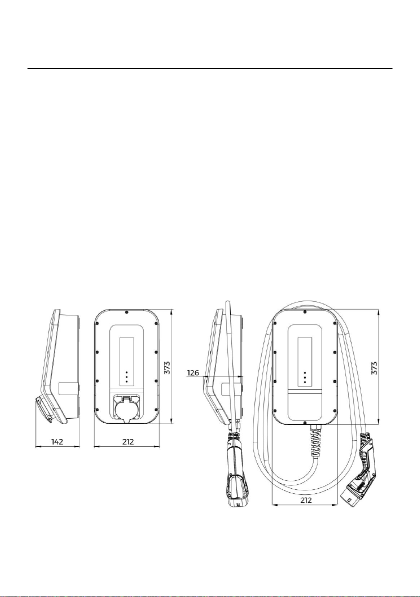
General dimensions
6
Evnex E & X Series Installation Manual | V210211
About this document
The following document describes the functionality and installation
procedures for the Evnex E & X Series of electric vehicle charging
stations.
Scope of this document
This document only refers to the following E & X Series charging stations,
please refer to the correct documentation if this does not apply.
Three phase: X22-T2T, X22-T2S
Single phase: E7-T1T, E7-T2T, E7-T2S, X7-T1T, X7-T2T, X7-T2S
Symbols
You will find the following symbols throughout this document. Please
pay attention to the recommendations.
CAUTION –Failure to follow these directions may cause
minor injury or damage to equipment.
WARNING –Failure to follow these directions may
cause serious injury or death.

7
Evnex E & X Series Installation Manual | V210211
Safety information
General information
•This unit should only be installed by those who are appropriately
qualified and skilled to do so.
•This unit has been designed and tested in accordance with IEC 61000-6-
3 and IEC 61000-6-2, however the installer is responsible for ensuring
that all local regulations and standards are complied with.
•This product is to be serviced only by Evnex approved technicians using
only Evnex supplied parts
•There are no user serviceable parts inside the charging station.
•Do not attempt to repair or modify the product
•It is the user’s responsibility to ensure that the cable is stored safely,
and not left where it could become a tripping hazard, or subject to stress
or damage.
•This charging station should only be used to charge a vehicle with a
compatible J1772 socket, or IEC 61851 type 1 or type 2 socket.
•Only cables which comply with IEC 62196-1 and IEC 62196-2 may be
used with this product
•Vehicle and charging cable shall be used as per the manufacturers
instructions
•Vehicle on-board charger required to comply with IEC 61851-1 and IEC
61851-21-1
•Avoid excessive application of moisture to charging cable connectors,
e.g. washing with hose

8
Evnex E & X Series Installation Manual | V210211
•Do not use harsh chemicals to clean this product. Periodic cleaning may
be done with a damp cloth and mild detergent if required
•Warning labels must not be removed
Risk of electric shock
•Read all instructions before installing or using this product
•If this product appears to be damaged in any way, it should be
electrically isolated and repaired or replaced. Damage includes fraying
or broken insulation on the power cable or any signs of cracking or
separation on the connector or charging unit
•This product should not be operated while in a “Fault” state and should
be electrically isolated until serviced by a qualified technician
•Appropriate upstream protection is required as per local regulations
•Never insert foreign objects in the charging cable connectors or
charging station socket
•Do not use extension cords or any kind of adapter with this product
•This product should not be used by children
•Avoid installing this product in locations that are prone to flooding

9
Evnex E & X Series Installation Manual | V210211
Disclaimer
Evnex Limited shall not be liable in any way for damage or injury that occurs
when using the product, and all warranties will be void where:
•The installation instructions have not been followed correctly
•The product has been installed by an unqualified person
•The product has been tampered with or modified
•The product has been used for a purpose other than it was designed and
intended for

10
Evnex E & X Series Installation Manual | V210211
Installation
Installation Notes
•Installer advised to follow anti-static procedures and to avoid touching
exposed electronic components
•Take extra care to avoid damage to internal components during
installation
•Product requires an upstream RCD to be installed with wiring as per
applicable local legislation.
•Product must be installed with appropriately rated wiring and upstream
circuit breaker
•Installation to be performed without charging cable attached for non-
tethered units
•Installer to use appropriate installation equipment and protective safety
clothing as per local legislation
•All exposed metal components such as pedestals shall be earthed as
per local legislation requirements
Site selection
•Where possible, protect the charging station from direct sunlight to
prevent charging speed reduction or charging interruption due to
overheating
•Do not cover unit or install in an area with poor airflow, such as a
cupboard

11
Evnex E & X Series Installation Manual | V210211
•Consider pedestrians and other traffic, ensure that the charging cable
does not pose a tripping hazard
•If possible, avoid installing the charging station in a place where it can
be damaged by falling objects, doors, vehicles or machinery
•Although this charger is designed for indoor and outdoor installations, it
is recommended that exposure to rain, snow, hail and direct sunlight is
minimized where reasonable to increase lifespan
•Do not allow this charging station to be subject to water spray such as
water blasters or high-pressure hoses
•The attachment surface must be sufficiently strong to withstand normal
use, non-tethered versions are subject to extra forces when plugging
and unplugging
•Ensure that the attachment surface is flat - an uneven surface may warp
the enclosure and prevent installation of the front cover
•Install trip hazard warning sign where appropriate or as required by local
legislation
•Install live electrical cable warning sign where appropriate or as required
by local legislation
•Product to be installed with adequate clearance to prevent operator
injury while using product. This includes inserting and removing
charging connector, wrapping and unwrapping cable and operating the
RFID card reader

12
Evnex E & X Series Installation Manual | V210211
Mounting notes
All charging stations (or the storage means for the vehicle
connector in tethered lead models) should be mounted at
least 800mm above ground level. The lowest point of the
vehicle connector when stored shall be at a height between
0.5m and 1.5m above ground level.
The sides of the unit are not vertical and should not be used
to find level. The template has flat sides suitable for placing a
level against before drilling. When screwing the unit to the
wall, use the top face of the unit to place a level against. The
unit must be mounted vertically as per illustrations.
Horizontal installation is not allowed.
Mounting holes must only be
drilled in the 5 locations
specified. It is the installers
responsibility to ensure
proper sealing of any drilled
holes, including installation
of provided sealing plugs. See arrows showing
the 5 drilling locations.

13
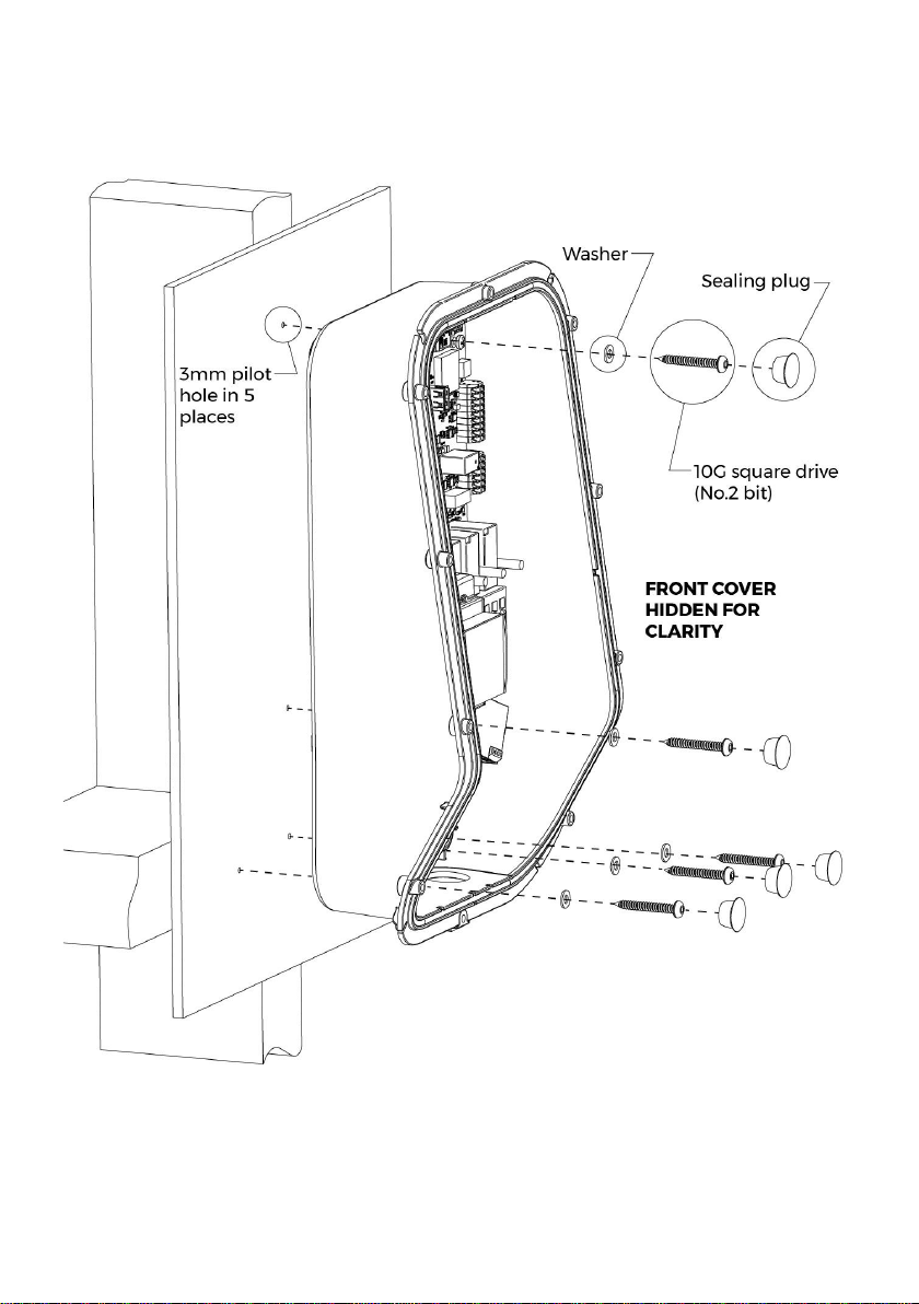
Evnex E & X Series Installation Manual | V210211
Fasteners
Locate the packet labelled INSTALLATION MANUAL & FASTENERS
containing the following:
*No.2 square bit required
**Torx T20 security bit required

14
Evnex E & X Series Installation Manual | V210211
Opening the unit
Remove the fasteners securing the front cover.
The cover has a tether to decrease risk of wire strain. This
tether can be looped into the recess in the top right corner of
the enclosure to keep the cover out of the way during
installation.

15
Evnex E & X Series Installation Manual | V210211
Mounting the unit
5 x 5mm holes must be drilled in the unit for the mounting screws.
Place the unit on a soft surface to prevent marking the unit while drilling
the holes.
Drilling too deep into the unit may cause the chuck of the drill
to damage wires. Remove any plastic swarf from the unit as
it could prevent water-tight installation of the sealing plugs
and the front cover.
The mounting surface must be flat to ensure that the unit is not twisted
as it is fixed against the chosen wall.
A cardboard drilling template is provided to allow easy marking out of the
5 mounting holes.
For timber framed walls, 3mm pilot holes are recommended.
For concrete walls, a 7mm masonry bit is required to allow insertion of
the supplied wall plugs.
The location of the optional rear entry hole (M25 or M32) is also provided,
along with the optional M12 hole location. M12 and M32 holes need to be
drilled by the installer if required.
16
Evnex E & X Series Installation Manual | V210211
Timber framed wall mounting example
17
Evnex E & X Series Installation Manual | V210211
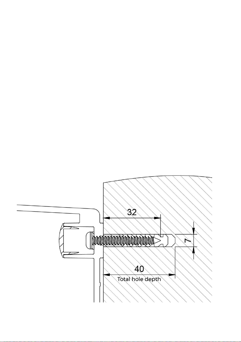
Solid wall mounting example
The diagram below shows a cross section of one of the five mounting
holes in a solid wall such as concrete.
For timber framed walls, the screws should enter solid structural framing
inside of the wall. If this is not possible, proper anchoring hardware,
suitable for the wall material and thickness, should be used.
For concrete or other solid walls, use the supplied wall plugs.
Recommended hole depth is 40mm with a 7mm masonry bit.
For all types of installation ensure that the washers are installed on the
screws and that the sealing plugs are installed after the screws are firmly
tightened.
18
Evnex E & X Series Installation Manual | V210211
Wiring connection
Always ensure that the main supply is isolated before
beginning work on the charging station installation.
The installer must ensure that the charging station is
correctly earthed.
The E & X Series are ‘mode 3’ charging stations. Due to
their high current consumption, they must be connected
to a dedicated feed from the main distribution board.
The E & X Series of charging stations are not designed
to charge vehicles that require ventilation systems
during charging.
Charging station is not to be powered on while the front
cover is open
19
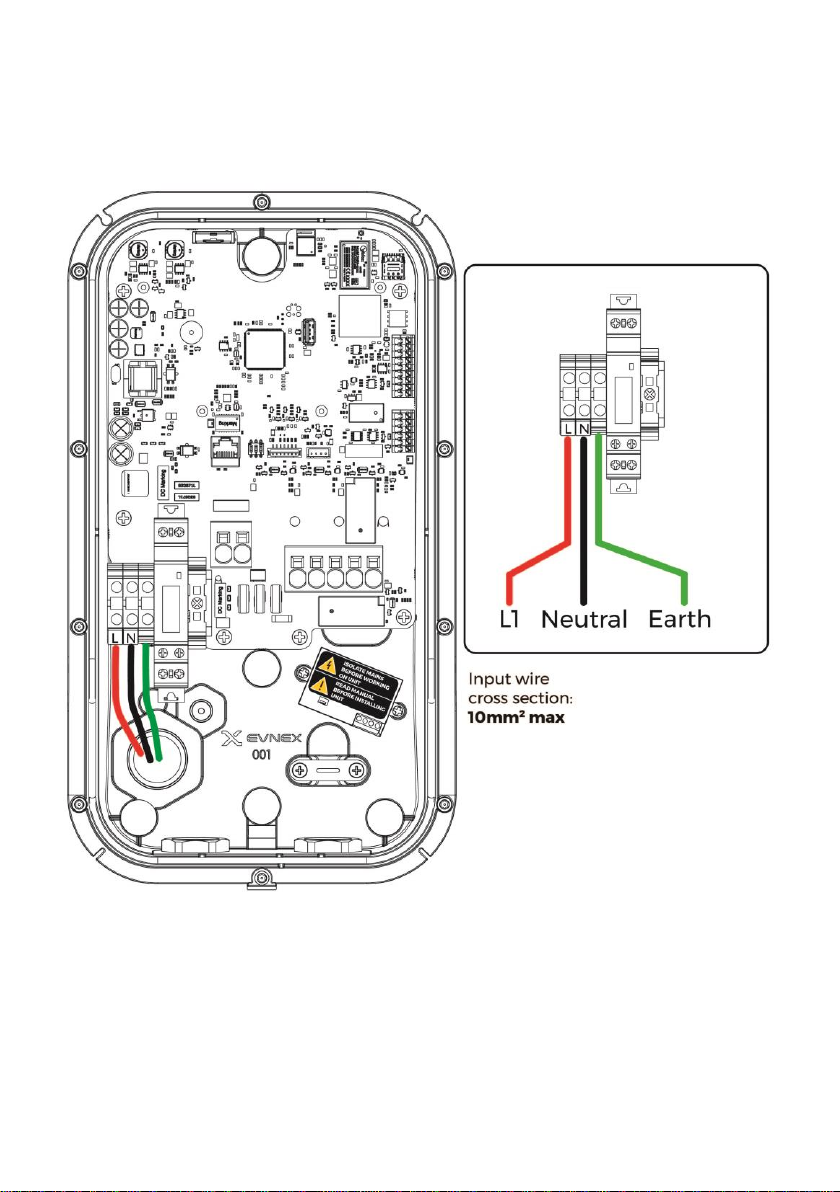
Evnex E & X Series Installation Manual | V210211
Single phase wiring example
20
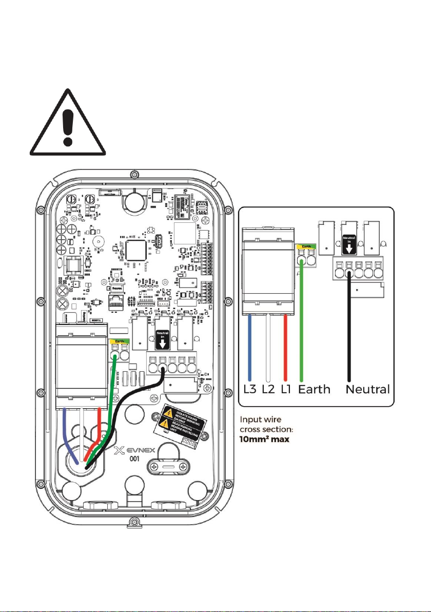
Evnex E & X Series Installation Manual | V210211
Three phase wiring example
Extra care is required with 3 phase wiring to ensure that the
input wires do not interfere with the front cover or charging
socket when the unit is closed. Excess wire may cause
interference and prevent the unit from being properly closed
This manual suits for next models
4
Table of contents
Other Evnex Batteries Charger manuals


