Docking Drawer DD 21 Slim Manual

Docking Drawer
Install Manual for DD 21 + 24 Slim
Applicable Models: 0290-00030, 0290-00030W,
0290‐00031, 0290‐00031W
CAUTION — READ CAREFULLY
• Failure to follow these instructions can cause death or permanent injury.
Do not work on live electrical circuits! Make absolutely certain power is
off before connecting the device!
• ThereareinstructionsprovidedwiththeUSBchargingoutlet–readthose
instructionsinadditiontothese.
• Thisproductisfordry,indoorandpermanentinstallationsonly.
• Installthedeviceinaccordancewithallnationalandlocalelectricalcodes.
General Information–
• TheDockingDrawerhasbeenlistedbyETLandcomplieswithUL962aand
CSAC22.2when installed in accordance with these instructions. Do not install
this product in a manner contrary to these instructions.
• TheDockingDrawerisdesignedforchargingpersonalelectronicsandotherlow
powerdevices.Itislimitedtoamaximumof3A@120VAC.
• Currentinstallationdiagrams,mountingdiagramsandwiringinstructionscanbe
foundintheDockingDrawerSpecicationLibrary.
Pleasevisitwww.dockingdrawer.comandclickontheSpecicationbutton.
Structure–
Power Cord Bracket
Receptacle Box
User Resettable Circuit Breaker
USB Charging Outlet
Cable Management Arms
0230-00004.r5|10/21/2015
1
Part No. 161100,161102,
161104, 161106
Distributed By:
www.cabinethardware.com

Top View of
Docking Drawer 21,
Mounted
0290-00030(W)
Top View of
Docking Drawer 24,
Mounted
0290-00031(W)
Side View
of Docking
Drawer,
Mounted
2
Preparing for a Docking Drawer Installation–
To prepare for a successful Docking Drawer installation please ensure that the cable management arms
are free and unobstructed by conrming following the specications:
• Thedistancefromthebackofthedrawertothe
wallwherethepowercordbracketmountsmust
beatleast3"asshown.
• Theinsidedepthofthedrawermustbeat
least23/4"
• Thedrawerglidesmustbepositionedinsuchas
waythatthedrawerextendsnomorethan18"
for0290-00030(W)and21"for0290-00031(W).
• Thecutoutforthereceptacleboxshouldbe
61/32"wideX215/16"high.Enlargingthecutout
by1/16"ineachdimensionisacceptableforease
ofmounting.Theinstallermustprovide(4)mounting
screwsforthereceptacleboxand(2)forthepower
cordbracket.
• Thereceptacleboxacceptsdrawerwallthicknesses
ofeither1/2"or5/8".

3
Installing the Docking Drawer Outlet–
1.
Withthedrawerclosedandthereceptaclebox
in
position,markthelocationoftherearmounting
bracketsothatthearmsarecentered.
2.InsertDockingDrawerthroughthereceptacle
boxcutoutinthebackofthedrawer.
4.Inserttherightrearmountingscrew
(notsupplied).
5.Mountthereceptaclebox.
6.Testmovement.Aligncablemanagementarms
sotheyarecenteredbetweenthedrawerbox
andthebackofthecabinetifnecessary.
7. PluginDockingDraweroutletintoanexisting
electricaloutlet.
3.ExtendtheDockingDraweroutletandinsert
theleftrearmountingscrew(notsupplied).

4
Removing the Receptacle Box–
ForasuccessfulDockingDrawerSlimchargingoutletinstallation,itisNOTnecessarytoremovethe
receptacleboxfromthecablemanagementarms.However,ifthereceptacleboxneedstoberemoved,
pleasefollowthesestepstodisconnect/reconnectthereceptacleboxfromthecablemanagementarms.
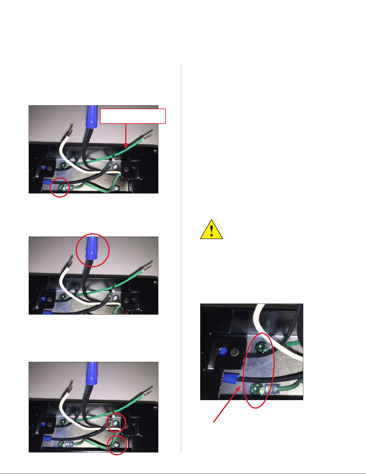
1.Removethecablearmgroundconnection
insidethereceptacleboxbyremovingthe
greengroundscrewandringterminalas
shown.DO NOTremovethegroundwire
thatgoestothereceptacle.
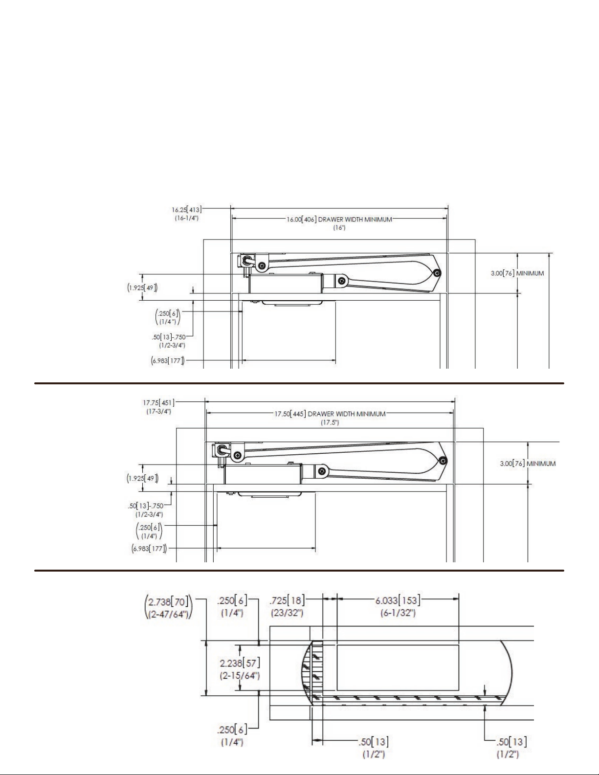
4.Mountthepowercordbracketinthecorrect
locationonthebackwallbehindthedrawer
asshowninthedrawing.
5.Installthedrawerinthecabinet,andholdon
totheendofthearmassembly.
6.Passthewiresfromthecablemanagement
armsintothereceptacleboxandreattach
thebracketusingthescrewdriverand
(2)#10screws.
7.Securethereceptacleboxtothebackofthe
drawerusingtheinstallersuppliedhardware.
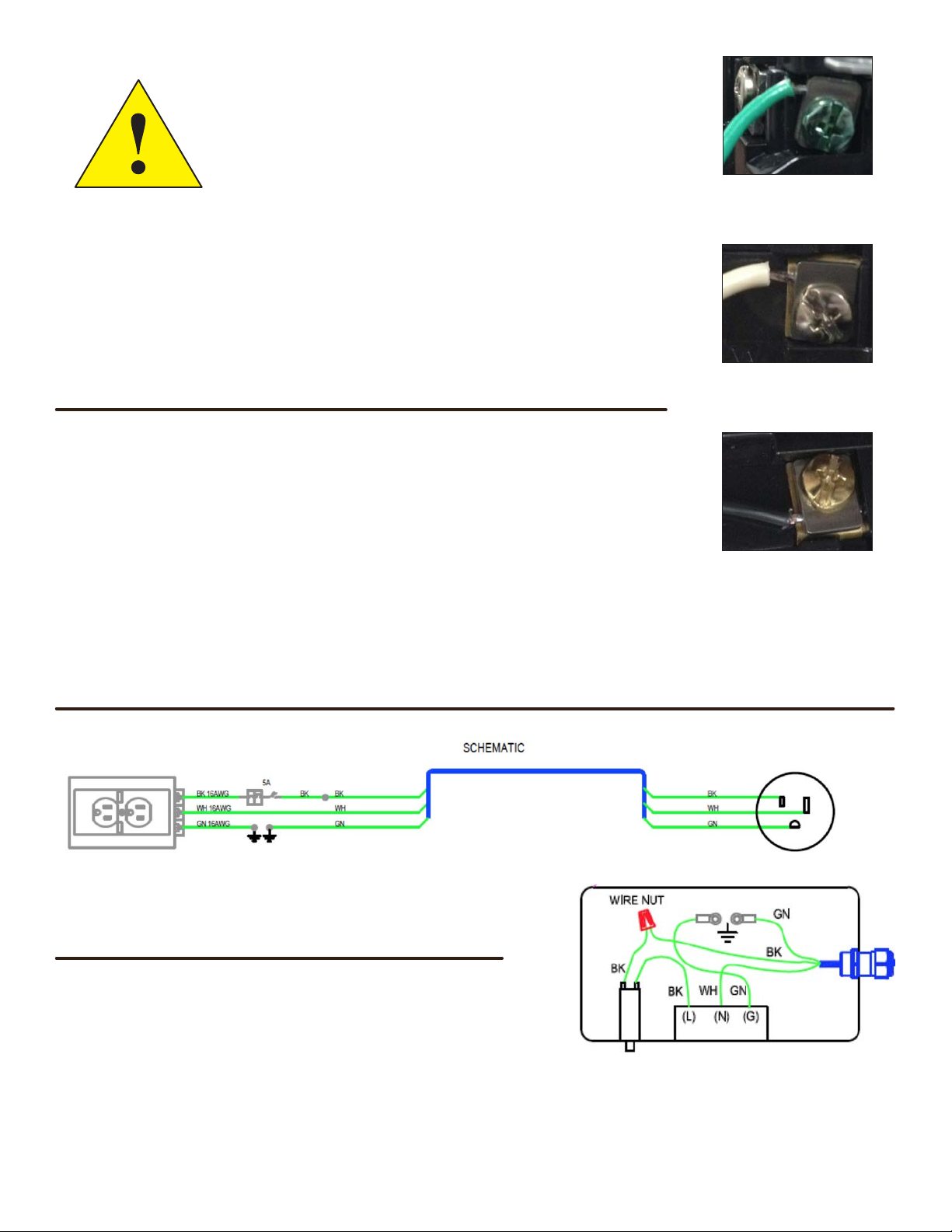
8.Reconnecttheblackwirefromthecircuit
breakertotheblackwirefromthecable
managementarmusingthebluewirenut.
9. DO NOT FORGET TO REATTACH THE
GROUND WIRE INSIDE THE RECEPTACLE
BOX. TORQUE SCREW TO 16-18 IN-LBS.
ENSURE THAT THE CIRCUIT BREAKER IS
WIRED IN SERIES WITH THE LINE (BLACK)
WIRE. SEE WIRE DIAGRAM.
2.Removethebluewirenutconnectingthe
blackwirefromthecablechaintotheblack
wiregoingtothecircuitbreaker.
3.UseaPhillipsheadscrewdrivertoremovethe
(2)#10screwsfrominsidethereceptaclebox.
Thiswillallowthecablearmbrackettobe
disconnectedfromthereceptaclebox.
MAKE SURE BOTH GROUND SCREWS
ARE SECURELY CONNECTED!
TORQUE TO 16-18 IN-LBS
DO NOT REMOVE

5
Reinstalling the Outlet–
Install the AC/USB charging outlet in the receptacle
box before plugging in the Docking Drawer.
•Afterthereceptacleboxhasbeencorrectlyinstalledinthe
backofthedrawerand(ifapplicable)allwirescorrectly
reattached,theAC/USBchargingoutletcanbeinstalled.
REMINDER: IF THE CABLE ARM GROUND WIRE WAS REMOVED DURING
INSTALLATION, MAKE SURE IT HAS BEEN REATTACHED AND TORQUED
PROPERLY. MAKE SURE THE CIRCUIT BREAKER IS WIRED IN SERIES WITH
THE LINE (BLACK) WIRE AS SHOWN IN THE WIRING DIAGRAM.
• FollowtheAC/USBchargingoutletinstructions(includedinoutletpackaging)
andconnecttheblack,white,andgreenwiresinaccordancewiththose
instructions.
Specications–
DockingDrawer™TechnicalSpecications:
• ACPower:125V,tamperresistantNEMA5-15Rduplexreceptacle.
• DC(USB)Power:5.2V,12.5WduplexUSBchargingreceptaclewith
integratedon/offsafetyswitch.
• Maxratedcurrent@125VAC:3A.Circuitisprotectedby5Apopout
breakeraccessiblefromtheuserside.Designedforchargingpersonal
electronicdevicesonly.
Operation–
• InstructionsspecictotheUSBchargingoutletare
includedwiththeoutletitself.
• TheDockingDrawerincludesa5Aresettablecircuit
breaker.Breakertripisindicatedbythewhitebutton
protrudingapproximately3/8”outfromthehousing.
Toreset,correctthesourceofovercurrentandpush
thewhitebuttonbackin.
Wiring Diagrams–
Receptacle Box Wiring
Green Wire (ground):
green screw
White Wire (neutral):
silver screw
Black Wire (line):
brass screw
This manual suits for next models
9
Table of contents
Other Docking Drawer Batteries Charger manuals