Evo-water soft duomatik 2 User manual

INSTALLATION GUIDE
soft duomatik 2
Before introduction of the softener the installation guide has to be read carefully.
For any disturbances cause by disregarding the instructions evo-water doesn’t accept liability.
evo-water oHG
Falkenstraße 2 72589 Westerheim
Tel.: +49 7333/925710
Fax : +49 7333/9257120
www.evo-water.com
info@evo-water.com

Safety instructions:
1. Before installation the softener:
Please refer to the corresponding installation –and operation
instructions in this manual.
2. Please refer to the local installation regulations and the general
directives, in particular DIN 1988 and EN1717, also the valid accident
prevention regulations.
3. With not designated use and improper service the manufacturer is
released from any liability.
4. Place of installation:
Before the installation please check the statics of the walls, covers and
grounds for loading capacity.
According to place of action a backflow must be installed
corresponding to local regulation before the arrangement.
For the protection of the central tax valves from rust, sand etc. a
suitable mudflap or fine filter should be inserted before the
arrangement. The filter pad of the fine filters should be exchanged
according to DINAR / DVGW at a distance of 6 months or after soiling.
Please ensure that no water damages are caused (e.g. by ground
expiry). The manufacturer is not liable for water damages .
The food water of the arrangement must correspond to the information
of the German drinking water order.
The room temperature must be at least 7°C and may not cross 50°C.
5. Changes in the system may not be made without consultation and
approval with evo-water oHG, for damages no other guarantee is
taken over.
6. The system serves exclusively for the removing of undesirable mineral
substances which retreat as a scale. It serves as a pure system
protection.

1. A) Parts:
1.
BYPASS
8.
BLENDING REGULATOR
2.
VALVE HOUSING
9.
HARDNESS REGULATOR
3.
RESIN TANK
10.
TO BRINE VALVE
4.
SALT CONTAINER
11.
CONNECTIONS (1/2", 3/4”, 1")
5.
BRINE VALVE (floater)
12.
TO DRAIN
6.
WATER INLET
13.
COMMUNICATION TUBES
7.
WATER OUTLET
14.
TUBES TO BRINE VALVE
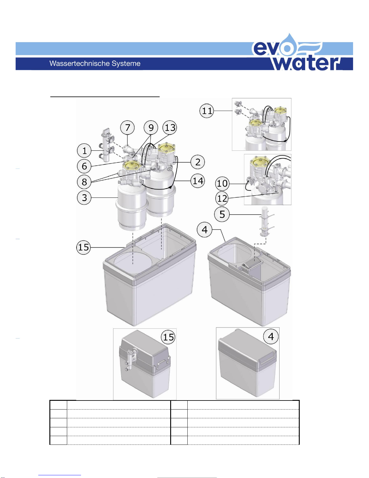
B) Parts Evo-water Duplex:
1.
BYPASS
9.
HARDNESS REGULATOR
2.
VALVE HOUSING
10.
TO BRINE VALVE
3.
RESIN TANK
11.
CONNECTIONS (1/2", 3/4”, 1")
4.
SALT CONTAINER
12.
TO DRAIN
5.
BRINE VALVE (floater)
13.
COMMUNICATION TUBES
6.
WATER INLET
14.
TUBES TO BRINE VALVE
7.
WATER OUTLET
15.
DEVICE CONTAINER
8.
BLENDING REGULATOR
2. Precautions:
Make sure you have all necessary tools on hand before you begin with the
installation.
Follow all local legal regulations.
Read this manual carefully. If you have any questions or remarks, please
contact your supplier.
Check incoming pressure: minimum 1 bar (dynamic), maximum 8 bar (static)
(15 PSI- 116 PSI). If necessary reduce incoming pressure.
Do not install the Softener close to a heating source (environment
temperature must be below 50°C).
Protect softener and drain (12) against frost.
Make sure you have the latest installation manual at hand. Check with your
supplier.
3. Installation:
3.1 Close main valve and make sure pressure is released from piping. This can be
done by opening at least one tap.
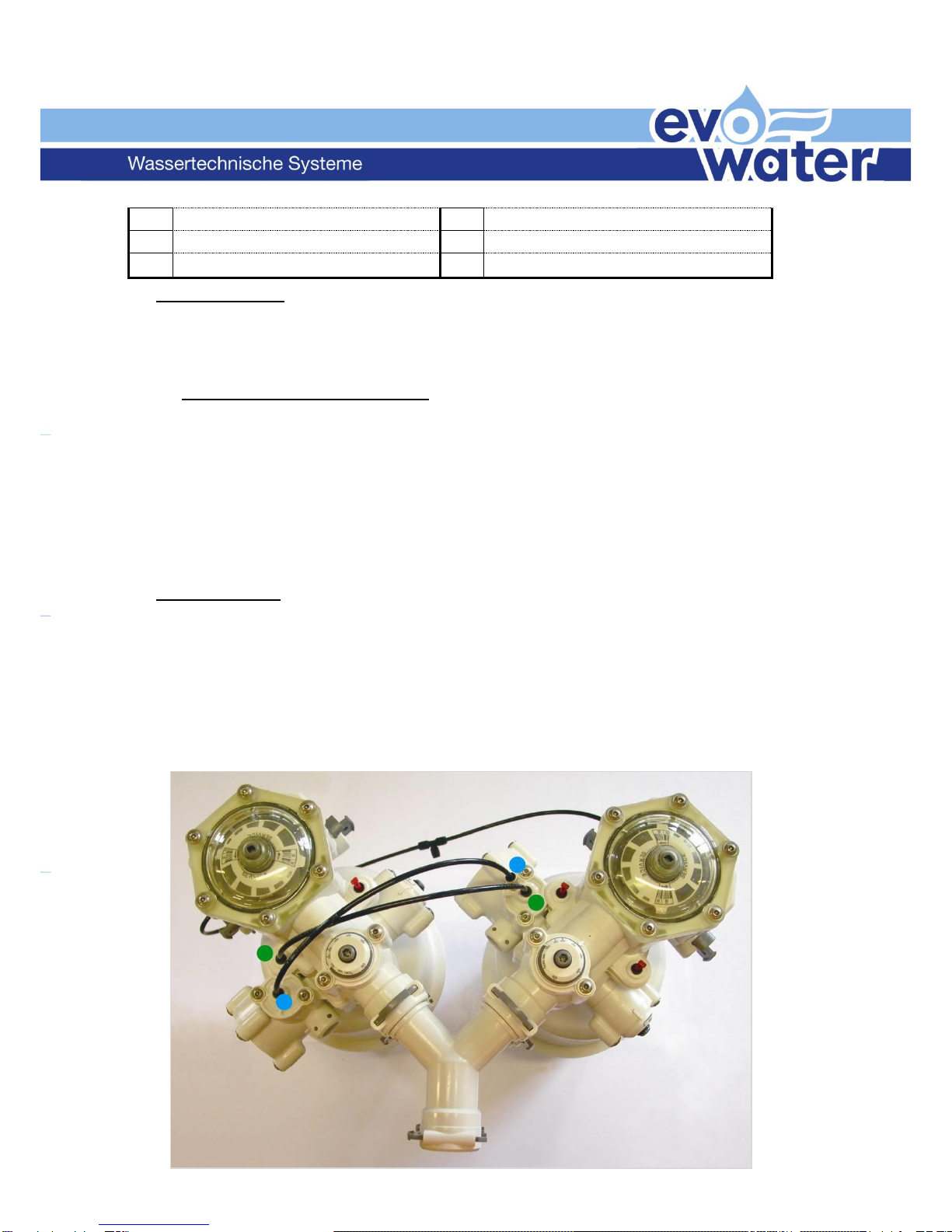
3.2 Check if all communication tubes are connected correctly.
See picture below: the two quick-release couplings marked with a green dot
should be connected by a communication tube (Ø4mm); the same should be
done for the two couplings marked with a blue dot.

3.3 Cut open main water supply in order to install direct connections to the
Softener or to install the Bypass (recommended). Follow the arrows on both
Bypass and softener for water inlet and outlet.
Pay attention that the inlet filter doesn’t fall out.
3.3.1
with Bypass with direct connections
The Evo-water Bypass has a ¾” connection. The direct connections on the
water softener are available in ½”, ¾” and 1”.
Caution: before installing the softener,
set the Bypass in “bypass” mode, not in
“service”.
3.3.2
Connect both drain outlets (#12) to a
local drain by means of a 13mm flexible
drain pipe as supplied by your local
supplier. If necessary use a Y-piece to
connect both drain outlets. In order to
guarantee that the device will keep on
functioning perfectly in the future, this
drain pipe should be spirally reinforced
to avoid later blocking and/or kinks.
Please protect the drain against frost
and heat (min. temp. 5°C, max. temp.
50°C).

CAUTION: For the installation of the flexible drain hose to the fixed piping,
please follow local legislation.
maximum
height and
distance of flexible
drain hose
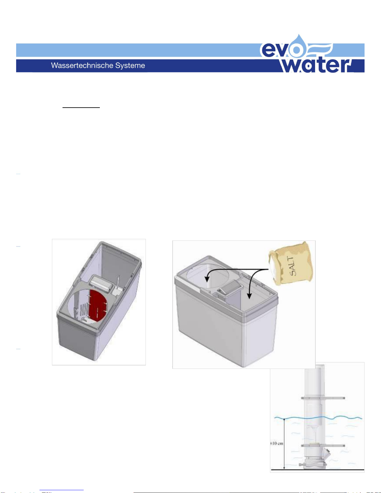
3.4 Pierce a hole (Ø5mm) in the side wall of the salt container for the brine tube.
The hole should be located approx. 10cm down from the top edge of the salt
container. After drilling the hole, remove all bits of plastic that have fallen into
the salt container.
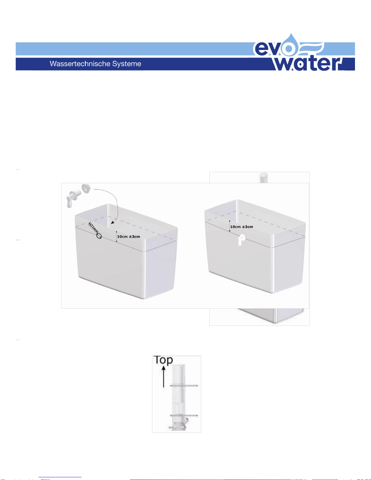
3.5
Make sure to install the supplied overflow tap. First, pierce a hole (Ø21 mm)
in the side wall of the salt container. The location of the hole is not important,
make sure however that it is approx. 10cm down from the top edge of the salt
container. Once the hole has been drilled, mount the overflow tap and secure
it with the supplied nut. After drilling, remove all bits of plastic that have
fallen into the salt container. A separate instruction leaflet with detailed
information has been added to the device. Please note that the hole for
the overflow tap must be situated BELOW the hole for the brine tube.
3.6 Connect the brine tube (Ø4mm) to the
quick-release coupling of the brine valve.
Push the tube in as far as possible. To
install the brine valve, open the cover by
pressing it gently at both sides. Now put
the brine valve in position, with the top side up.
Make sure the valve goes all the way down to the
bottom of the salt container. Close the cover.
3.7 Insert the Brine tube into the salt container using
the 5 mm hole, and connect it to the T-piece
which joins the tubes from both units. Insert the
tube as far as possible (to stop) into the T-piece.
Make sure not to squeeze the tube; avoid
kinks.

WHEN INSTALLING A DUPLEX EXTERNAL, PLEASE PROCEED TO “4. Settings”.
WHEN INSTALLING A DUPLEX DUET, PLEASE PROCEED TO 3.8
3.8 At the bottom of the container there are two
supports which the device will rest on. Check
the correct location of these supports (refer to
the image on the right).
With the round opening nearest to you, the
arrows should point to the right (as in the image
on the right).

3.9 Place the device in the container in such a way that the connections point in
the opposite direction of the arrows on both supports at the bottom of the
container.
3.10 A hole needs to be drilled in the side wall of the container for the tube which
connects the brine valve to the T-piece. This hole has to be drilled following
the instructions in 3.4. Disconnect the tube, lead it through the hole and
reconnect it to the T-piece.
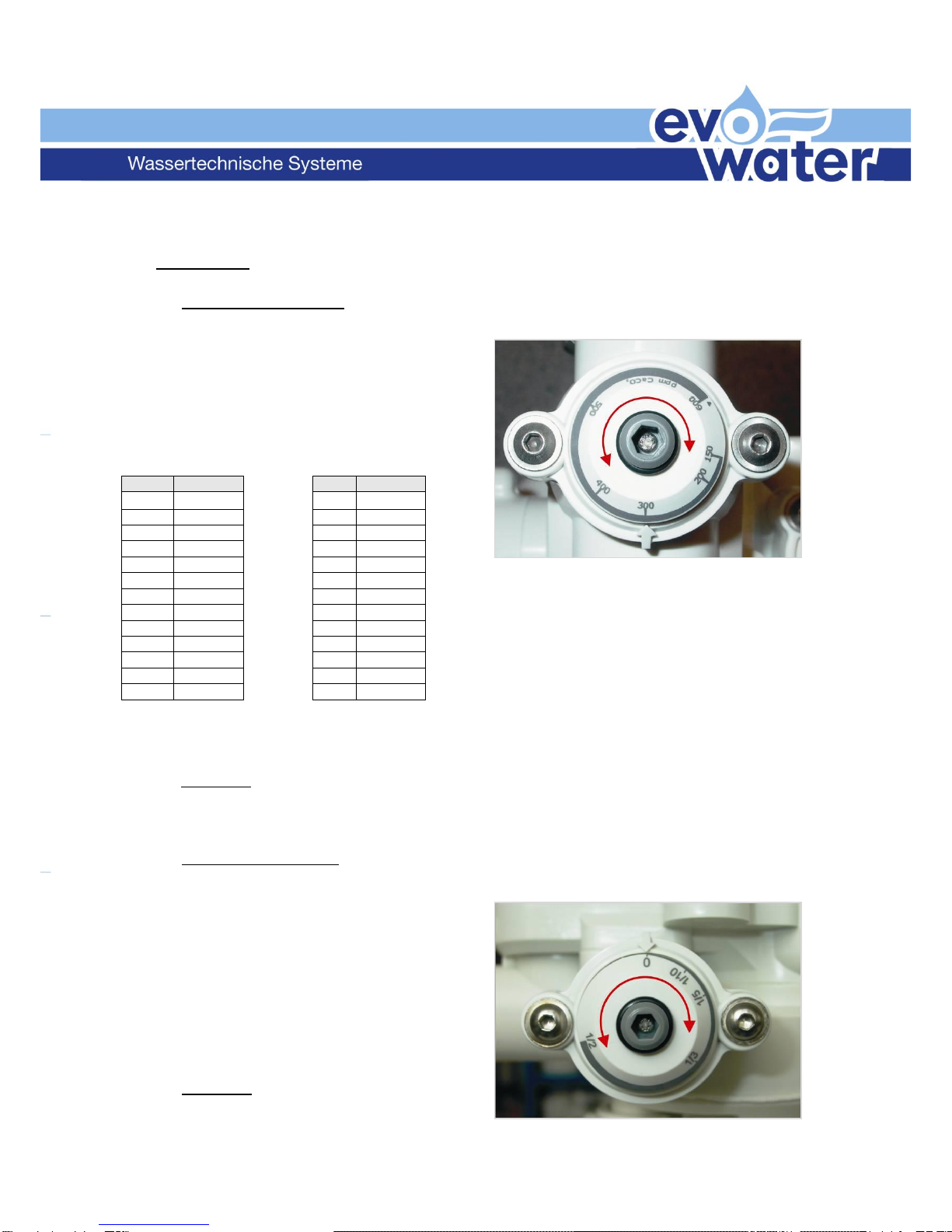
4. Settings:
4.1 Hardness regulator:
=part number 9 on the illustration on page 1
Measure the hardness of incoming
water by means of a hardness test
kit (not supplied by evo-water). evo-
water uses ppm settings of CaCO3.
(10 ppm CaCO3= 1°fh) (1°dh =
1,78°fh)
Adjust the hardness regulator to the measured value. This requires a hex key
number 5.
Remark: always set regulator on both units to the same setting.
4.2 Blending regulator:
= part number 8 on the illustration on page 1
With the blending regulator, you can
determine the outgoing hardness.
Depending on the desired residual
hardness, set outgoing hardness
with a hex key number 5. The
setting is proportional, i.e. 1/10 –
1/5 –1/… of total incoming
hardness.
Remark: always set regulator on
both units to the same setting.
dh
ppm
dh
ppm
9°
160,2
22°
391,6
10°
178,0
23°
409,4
11°
195,8
24°
427,2
12°
213,6
25°
445,0
13°
231,4
26°
462,8
14°
249,2
27°
480,6
15°
267,0
28°
498,4
16°
284,8
29°
516,2
17°
302,6
30°
534,0
18°
320,4
31°
551,8
19°
338,2
32°
569,6
20°
356,0
33°
587,4
21°
373,8
34°
605,2
5. Start up:
5.1 Leave Bypass in “bypass” mode, open main valve and flush for several
minutes in order to avoid impurities from entering the softener. When you do
not use a Bypass, open the main valve slowly as described in 5.4.
5.2 Before filling the salt container with salt, check that the partition wall is
correctly in place (between the small brackets, and all the way down to the
bottom of the salt container). Please refer to the drawing below, where it has
been coloured in red to make it clearly visible. Fill the salt container on both
sides of the partition wall.
Use only specific salt tablets that are suitable for softeners.
5.3 A
dd water in the salt
container until the water level is approx. 10cm (4”) high.
(the floater on the brine valve must be afloat)

5.4 Turn the bypass slowly to
“service” mode. Open the main
valve when you do not use a
Bypass.
5.5 Open a tap behind the softener
so a flow runs through it. Some air may flow from the tap; this comes from
the softener. This will happen only once; at start-up. Once only water flows
from the tap, and no more air, close the tap.
5.6 Perform a manual regeneration.
5.6.1
Choose one of both units to perform a manual regeneration. Use a hex key
number 5 to turn the program disk (PRG) manually.
Turn PRG counter clockwise until it is in above position. When the arrow and
the small line on the transparent cover reach the area marked by “B”
(brining), the regeneration will start. Immediately, the PRG will drop down a
little (you will be able to see and hear this). “R” stands for refill (refilling the
container with water at the end of the regeneration stage). To make sure the
softener is in regeneration, there should be a small water flow to the drain,
and the water level in the container should drop.
5.6.2
Let regeneration perform until it stops automatically. The estimated time is
approx. 12 minutes. When regeneration has stopped, no more water flows to
the drain. This is a clear indication that the regeneration stage is over.
5.6.3
Open a tap behind the softener for several minutes to allow residual water to
be flushed from the tubing.
5.6.4
Check outgoing hardness with a “hardness test kit” (not supplied by evo-
water). Adjust blending if necessary.
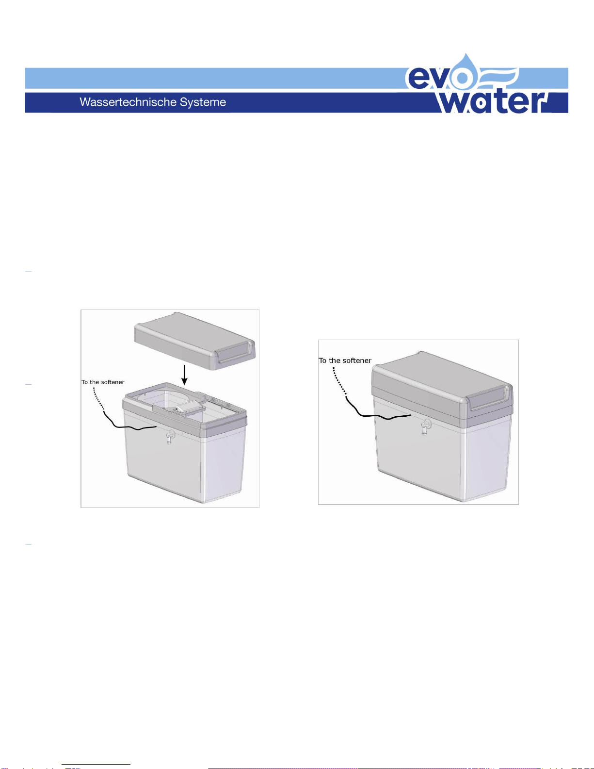
5.7 Place the cover on the salt container.
Connect
the overflow tap to the drain.
5.8 (for Duplex Duet only)
Place the cover on the container which holds the device.

REMARKS:
It is recommended that a water softener is installed by a
professional. Although the Softener is probably the
easiest and safest softener on the market, it is imperative
that all necessary precautions are taken and local
legislation is followed.
This installation guide is written to help the professional
installer keeping in mind that this person has essential
knowledge about hydraulic softeners and domestic
plumbing.
Proper working of the softener will be determined by proper installation.
An annual control of your Softener will guarantee optimal functioning and a long operating
life.
The EVO-WATER oHG is proud of its achievement in having provided in what we
believe to be the best softener available today.
Moreover, we are proud to have you as a customer. We will do our utmost to
deserve your trust.
evo-water oHG
Falkenstraße 2, 72589 Westerheim
Tel.: +49 7333/92 57 10
Fax : +49 7333/92 57 120
info@evo-water.com
www.evo-water.com
Table of contents
Other Evo-water Water Dispenser manuals


Popular Water Dispenser manuals by other brands

IBC Water
IBC Water AST0715MP-960 Installation & operating instructions

Lancaster Water Treatment
Lancaster Water Treatment X FACTOR LX15 Series Installation, operating and service manual

Elkay
Elkay EMABF8 Series Installation & use manual

Oasis
Oasis Osmosis Home installation manual

Monarch Water
Monarch Water ULTIMATE MINI AQUA HE install guide

Haier
Haier HLM-109B instruction manual


