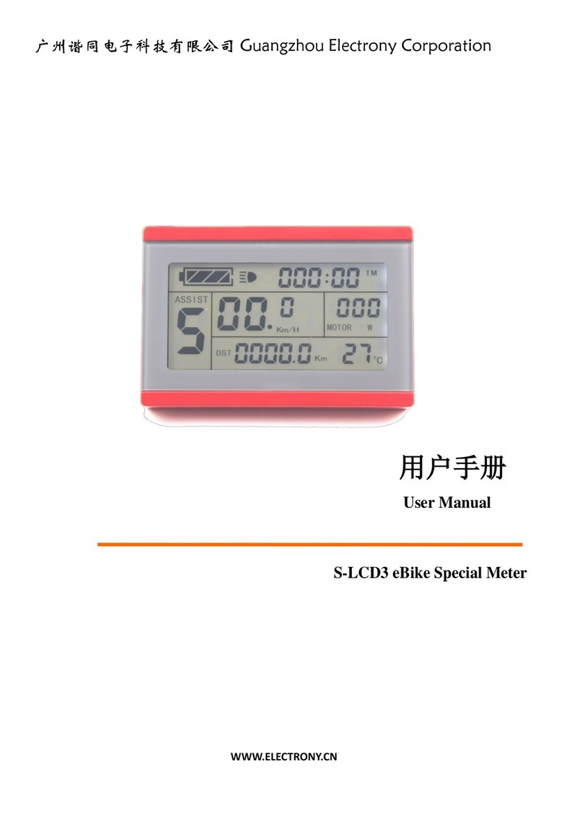
Evobike LCD-X3 User manual

USERS GUIDE
LCD–X3
Version:V2.1
Date:2007 - 10-18

Catalog
About the user manual....................................................1
Main material and color..................................................1
Appearance size chart........................................................2
Function overview and button definition..............2
Functional Overview..........................................................2
Normal display area...........................................................3
Note for users.....................................................................3
Installation Notes..............................................................4
Normal operation..............................................................4
Power on/off..........................................................................4
Instrument display interface............................................5
Power display.........................................................................6
Error code display................................................................7

User settings................................................................8
Backlight headlights on..........................................8
6KM implementation................................................8
PAS gear setting..........................................................8
Internal parameter setting....................................9
Enter settings................................................................9
Exit settings.................................................................12
Frequently Asked Questions and Answers...12
Quality commitment and warranty scope....12
Lead connection diagram....................................13
Version change.........................................................14

关于用户t te user manual
About the user manual
Dear users, in order to better operate your electric car
, please read the LCD-X3 V2.1 instrument manual
carefully before use. We will tell you every aspect of
the instrument use in the most concise language,
including hardware installation and setting to the
normal use of the instrument. At the same time,
it helps you to solve the confusion and obstacles
that may arise.
Main material and color
The LCD-X3 V2.1 product uses PC material. The shell material is
allowed to be at -20℃
It can be used normally at a temperature of 60℃,
and good mechanical properties can be guaranteed.
Appearance size chart

1

Function overview and button definition
Functional Overview
LCD-X3 V2.1 provides you with multiple functions and displays to
meet your riding needs. You can charge your mobile phone while
you are riding;
The contents displayed are:
◆Power display
◆Motor power display
◆Speed display (including real-time speed display, maximum
speed display and average speed
Degree display)
◆Mileage display (including single mileage display and total
mileage display)
◆Backlight on
◆Error code display ◆Multiple setting parameters
Normal display area
Normal display interface
2

Note for users
Pay attention to safety during use, and do not plug or unplug the
meter when it is powered on. Try to avoid bumping the instrument.
The film used by the meter is a waterproof film, please do not
tear it, so as not to affect the water resistance of the meter
can.
Regarding the background parameter setting of the instrument,
please do not change it at will, otherwise it cannot be guaranteed.
Ride often.
When the meter cannot be used normally, it should be repaired
as soon as possible.
3

Installation Notes
Fix the instrument on the handlebar and adjust the viewing
angle. When the electric bicycle is powered off, just plug
the connector of the instrument and the corresponding
connector of the controller to complete the installation.
Normal operation
Power on/off
After long pressing the 【MODE】key, the meter starts to
work and provides the working power of the controller. In
the power-on state, long press the [MODE] key to turn off
the power of the electric vehicle. In the shutdown state, the
meter no longer uses battery power and the leakage
current of the meter is less than 1uA. If the electric vehicle
is not used for more than 5 minutes, the meter will
automatically shut down.
4

Instrument display interface
After the meter is turned on, the meter defaults to display real-time speed.
Short press【MODE】key to switch display information. Displayed in turn:
single mileage TRIP-----single time TIME-------power display WATT------single
average speed AVG------single maximum mileage→MAX ------Total mileage
ODO
Real-time speed, single mileage display real-time speed, single time display
Real-time speed, real-time speed of single maximum mileage, single
average speed
Real-time speed, real-time speed of single maximum mileage, single
average speed
5

Power display
When the battery voltage is high, the five-segment LCD will be on.
When the battery voltage is low, the battery
The outer frame flashes, indicating that the battery is seriously
undervoltage and needs to be charged immediately
Battery undervoltage flashes battery power display
6

Error code display
When the electric vehicle electronic control system fails, the meter
will automatically display the error code,
Refer to Appendix 1 for the definition of detailed error codes.
Error code display interface
The fault display interface can only be exited when the fault is
eliminated. After the fault occurs, the electric vehicle
Will not be able to drive normally.
Attached Table 1: Error code definition table
Error code Definition
21
Abnormal current
22
Handlebar abnormal
23
Motor phase loss
24 Motor Hall signal is
25
Abnormal braking
30
Abnormal communication

7
User settings
Backlight, headlights on
Long press [+] for 2 seconds to turn on the headlights, and the
backlight is on.
6KM implementation
When the motor is stationary, press and hold [-] for 2 seconds to
enter the 6KM implementation state,
Release the button to exit the 6KM implementation state.
6KM implementation icon display
PAS gear setting
PAS gear is 0-9, optional (this gear display can be modified
according to customer requirements,
0-3 gears, 0-5 gears)), short press【+】】【- 】to switch gears.

PAS gear setting area
8
Internal parameter setting
Enter settings
After the meter is turned on, press and hold [+]] [-] at the same
time to enter the setting interface; [M] is the letter
Switch between information, P01-P08 selection; short press 【+】
】【-】to select the corresponding value. 30 seconds
If there is no operation information, it will automatically exit and
save the current settings. You can also press and hold [+]] [-] to exit
Exit the setting interface, if no operation is performed within one
minute, the meter will automatically exit the setting
status. .
P01: Wheel diameter setting (unit: inch)
8,10,12,14,16,18,20,22,24,26,700C,28
P02: Speed measuring magnet setting 1-100

9
P03: Non-zero start selection
0-1 (0-zero start, 1-non-zero start), this function needs controller support.
P04: KM/MILE switch
P05: Battery working voltage selection 24V, 36V, 48V

10
P06: Sleep time setting, the default value of the factory sleep time is 5
minutes
When the motor is stationary and has no power output, the meter will
automatically turn off after 5 minutes and switch off.
Cut off the controller signal power supply. 0-60 (unit: minutes), 0 means no
sleep
P07: Speed limit setting, the default value of the maximum riding speed of
the instrument is 25Km/h. more
Changing this value can set the maximum riding speed of the electric
vehicle, when the electric vehicle exceeds the set value
When the time, the controller will stop the power supply to the motor to
protect the safe driving of the rider.
12-40, 40 is unlimited speed
P08: Hall speed mode

0: Display the hub hall communicated from the controller
1: Display the hub hall directly connected from the instrument
11

Frequently Asked Questions and Answers
Q: Why can't it be turned on?
Answer: Check whether the battery is turned on or the leakage lead is
broken.
Question: How to deal with the fault code displayed by the instrument?
Answer: Go to the repair point for repairing the electric vehicle in time.
Quality commitment and warranty scope
1. Warranty information:
1). Anything caused by the quality of the product itself under normal use
During the warranty period, the company will be responsible for granting a
limited warranty.
2). The warranty period of the product is within 24 months from the
factory.
2. The following conditions are not covered by the warranty
1). The shell is opened
2). The connector is destroyed
3). After the instrument leaves the factory, the casing is scratched or
damaged
4). The lead wire of the instrument is scratched or broken
5). Due to irresistible (such as fire, earthquake, etc.) or natural disasters
(such as lightning strikes)
Etc.) failure or damage caused by
6). The product is out of warranty

12
Lead connection diagram
Standard connector line sequence
6 core waterproof head male end front view
Table: Wire sequence table of standard connectors
NO
wiring color
Function
1
Red (VCC) instrument power cord
2
Blue (K) electric door lock wire of controller
3
Black (GND) instrument ground wire
4
Green (RX) Data receiving line of the meter
5
Yellow (TX) data transmission line of the meter
6
White (Deng)
output headlight wire
Note: The lead adopts a waterproof connector, and the user
cannot see the color of the lead in the harness.
13

版本变更
Version change
The instruction manual of this instrument is the universal
software version of Wuxi Qishang Technology Co., Ltd.
This (V2.1 version) operation manual. Instrument software
version used on some vehicles
There may be slight differences between this manual and
this manual, and the actual version shall prevail.
14
Table of contents
Other Evobike Bicycle Accessories manuals
