manuals.online logo
Brands
  1. Home
  2. •
  3. Brands
  4. •
  5. Profile Design
  6. •
  7. Bicycle Accessories
  8. •
  9. Profile Design L2 User manual

Profile Design L2 User manual

L2-Halterungssystem
Installationsanleitung
L2 Bracket System
Installation Instructions
Note to Dealers: If you install this product for the consumer, please provide him/her with this owner’s manual after installation.
Thank you for purchasing the Prole Design Aerobar Featuring the L2 Bracket System. Please read these instructions thoroughly before attempting to install this item. Proper
installation is required for compliance with the Prole Design warranty policy. If you are not familiar with installation of aerobars or their accessories, please seek the assistance of
your local Prole design dealer by logging on to www.prole-design.com and using "dealer search" or by calling the Prole Design customer service number.
Hinweis für Händler: Wenn Sie dieses Produkt für den Kunden installieren, übergeben Sie ihm nach der Installation bitte diese Bedienungsanleitung.
Vielen Dank, dass Sie sich für den Aerobar mit J2-Halterungssystem von Prole Design entschieden haben. Bitte lesen Sie diese Anweisungen aufmerksam, bevor Sie den Artikel
installieren. Zur Einhaltung der Garantiebestimmungen von Prole Design ist eine sachgemäße Installation erforderlich. Wenn Sie mit der Installation von Aerobars oder deren
Zubehör nicht vertraut sind, wenden Sie sich bitte an Ihren örtlichen Prole-Design-Händler; verwenden Sie dazu die „Händlersuche“ unter www.prole-design.com oder rufen Sie
den Prole-Design-Kundendienst an.
1. Remove the M6 bolts from the bottom of the clamp.
2. Place the bracket onto the bar and connect bottom U bracket to the aerobar bracket. Thread in the bolts by hand.
3. Adjust the width and tilt of the bar to desired position. Evenly tighten the M6 bolts to 6Nm (53in.lbs).
Do not route the brake or shift cables between the aerobar bracket and basebar.
1. Entfernen Sie die M6-Schrauben von der Unterseite der Klemme.
2. Platzieren Sie die Halterung auf dem Lenker und verbinden Sie die untere U-Halterung mit der Aerobar-Halterung.
Drehen Sie die Schrauben von Hand fest.
3. Passen Sie die Breite an und neigen Sie den Lenker in die gewünschte Position. Ziehen Sie die M6-Schrauben mit
6 Nm (53 in.lbs) gleichmäßig fest.
Führen Sie Brems- und Schaltzug nicht zwischen Aerobar-Halterung und Basislenker hindurch.
1.、2.、3.1.、2.、3.
7.、8.7.、8.
4.4.
5.5.
6.6.
5. Place the armrest in the preferred location on the bracket. Insert the M6 bolt through the armrest and into the bracket.
Using the 4mm Allen wrench thread the bolt until it is snug. Repeat for the second bolt leaving it slightly loose to allow for
adjustment.
NOTE: Bolts can be installed side by side or front to back for optimized armrest positioning.
5. Platzieren Sie die Armlehne in der gewünschten Position an der Halterung. Stecken Sie die M6-Schraube durch die
Armlehne und in die Halterung. Ziehen Sie die Schraube mit dem 4-mm-Inbusschlüssel sicher fest. Wiederholen Sie den
Vorgang bei der zweiten Schraube; lassen Sie sie zur Anpassung ein wenig locker.
HINWEIS: Schrauben können zur optimierten Armlehnenpositionierung nebeneinander oder von vorne
nach hinten installiert werden.
6. Rotate the armrest to the preferred angle relative to the extension. Tighten evenly to 4.7Nm (42in.lbs).6. Drehen Sie die Armlehne in den gewünschten Winkel zur Erweiterung.
Ziehen Sie sie gleichmäßig mit 4,7 Nm (42 in.lbs) fest.
7. Press the pad onto the armrest and hold rmly for 30 seconds. Repeat for the other armrest.
8. Recheck the bolts for tightness after rst usage and periodically thereafter to ensure secure
attachment of the aerobar system.
7. Drücken Sie das Polster 30 Sekunden lang fest auf die Armlehne. Wiederholen Sie den Vorgang bei der anderen Armlehne.
8. Prüfen Sie die Schrauben nach dem ersten Einsatz, später in regelmäßigen Abständen auf festen Sitz;
vergewissern Sie sich, dass sich das Aerobar-System nicht lockert.
Tools and materials required: 4mm Allen wrench, 5mm Allen wrench and Torque wrench (in-lbs/Nm)
Threaded areas have been pre-treated by Prole Design during production with a special blue thread locking compound. This special compound is easy to detect on the threads of
all bolts provided. If you cannot detect this thread locking compound or if you have cleaned it off through normal maintenance, re-apply a suitable blue thread locking compound as
available from Loctite or another company before assembly.
Benötigte Werkzeuge und Materialien: 4-mm-Inbusschlüssel, 5-mm-Inbusschlüssel und Drehmomentschlüssel (in-lbs/Nm)
Gewinde wurden von Prole Design während der Produktion mit einer speziellen blauen Gewindesicherungsmasse vorbehandelt. Diese spezielle Masse ist an den Gewinden aller
mitgelieferten Schrauben deutlich sichtbar. Falls der Lack nicht erkennbar sein oder sich bei der regulären Wartung ablösen sollte, tragen Sie vor der Montage einen geeigneten,
blauen Schraubensicherungslack (beispielsweise von Loctite oder einem anderen Anbieter) auf.
WARNING
WARNUNG
L2 Bracket System 06/28/2016
• Any failure to follow these warnings and instructions can result in breakage, slippage and or other malfunctioning
of this Prole Design component causing a loss of control of the bicycle with serious injuries. [AP1100-1-1]
• A creaking component can be a sign of potential problems. Make sure all contact surfaces between components
are clean, all bolt threads are greased or are treated with proper thread lock and tightened to Prole Design's (or the
bike manufacturers) specications and all components are properly sized to t together. If you continue to experience
creaking stop using the Prole Design component and call Prole Design customer service. [AP0601-2-2]
• Under tightening a bolt can result in a part coming loose while riding and an over tightened bolt can break unexpectedly
or strip the threads it is engaging while riding also resulting in a loss of control. All bolts must be tightened to
Prole Design's (or the bike manufacturer's) torque specications. On the rst and any subsequent assembly examine
all male and female threads and bolts for stripped threads, cracks and any required lubrication or thread locking
compound. [AP1100-3-2]
• Periodically, closely examine all surfaces of this Prole Design component (after cleaning) in bright sunlight to check
for any small hairline cracks or fatigue at "stress points" (such as welds, seams, holes, points of contact with other
parts etc.). If you see any cracks, no matter how small, stop using the part immediately and call Prole Design
customer service. [AP0302-4-2]
• Whenever you install any new component on your bike make sure you thoroughly try it out close to home (with your
helmet) where there are no obstacles or trafc. Make sure everything is working properly before going off on a ride or
to a race. [AP1100-5-1]
• Racing (road, mountain or multi-sport) places extreme stress on bicycles and their components (like it does riders)
and signicantly shortens their usable life. If you participate in these types of events, the lifetime of the product may be
signicantly shortened depending upon the level and amount of racing. The “normal wear” of a component may differ
greatly between competitive and non-competitive uses, which is why professional level riders often use new bikes and
components each season as well as having their bikes serviced by professional mechanics. Particular care should be
placed in the regular examination of your bicycle and it’s components to insure your safety. [AP1100-6-1]
• A number of factors can reduce the life of this component to less than its warranty period. Rider size and/or strength
and riding style, high mileage, rough terrain, abuse, improper installation, sweat, adverse environmental conditions
(such as salt air or corrosive rain), travel damage (especially if bike and components are repeatedly disassembled and
then reassembled) and crashes or accidents can all contribute to the shortening of the life of this component. The more
factors that are present, the more the life of the component is reduced. [AP0801-7-2]
• Make sure the handlebar clamp area diameter matches that of the stem clamp diameter (i.e. 31.8mm, 26.0mm or
25.4mm). An incorrect match could result in handlebar and or stem damage, slippage or breakage causing a possible
loss of control and injury. [B0706-4-1]
• Carbon fiber handlebars require special attention and maintenance. For installation of a stem with carbon fiber
handlebars please refer to handlebar manufacturer’s instructions prior to installation. [ST1100-1-1]
• Make sure you periodically recheck rear clamp (fork attachment) and front clamp (handlebar attachment) stem bolt
tightness (especially after riding on rough terrain) to insure a good attachment. [ST1100-2-1]
• Forks with carbon fiber steering tubes require special attention and maintenance. Refer to fork manufacturer’s
instructions. [ST1100-5-1]
• Any failure to follow these warnings and instructions can result in breakage, slippage and or other malfunctioning of
this Prole Design component causing a loss of control of the bicycle with serious injuries. [AP1100-1-1]
• A creaking component can be a sign of potential problems. Make sure all contact surfaces between components are
clean, all bolt threads are greased or are treated with proper thread lock and tightened to Prole Design's (or the bike
manufacturers) specications and all components are properly sized to t together. If you continue to experience
creaking stop using the Prole Design component and call Prole Design customer service. [AP0601-2-2]
• Under tightening a bolt can result in a part coming loose while riding and an over tightened bolt can break
unexpectedly or strip the threads it is engaging while riding also resulting in a loss of control. All bolts must be
tightened to Profile Design's (or the bike manufacturer's) torque specifications. On the first and any subsequent
assembly examine all male and female threads and bolts for stripped threads, cracks and any required lubrication or
thread locking compound. [AP1100-3-2]
• Periodically, closely examine all surfaces of this Prole Design component (after cleaning) in bright sunlight to check
for any small hairline cracks or fatigue at "stress points" (such as welds, seams, holes, points of contact with other
parts etc.). If you see any cracks, no matter how small, stop using the part immediately and call Profile Design
customer service. [AP0302-4-2]
• Whenever you install any new component on your bike make sure you thoroughly try it out close to home (with your
helmet) where there are no obstacles or trafc. Make sure everything is working properly before going off on a ride or
to a race. [AP1100-5-1]
• Racing (road, mountain or multi-sport) places extreme stress on bicycles and their components (like it does riders) and
signicantly shortens their usable life. If you participate in these types of events, the lifetime of the product may be
signicantly shortened depending upon the level and amount of racing. The “normal wear” of a component may differ
greatly between competitive and non-competitive uses, which is why professional level riders often use new bikes and
components each season as well as having their bikes serviced by professional mechanics. Particular care should be
placed in the regular examination of your bicycle and it’s components to insure your safety. [AP1100-6-1]
• A number of factors can reduce the life of this component to less than its warranty period. Rider size and/or strength
and riding style, high mileage, rough terrain, abuse, improper installation, sweat, adverse environmental conditions (such
as salt air or corrosive rain), travel damage (especially if bike and components are repeatedly disassembled and then
reassembled) and crashes or accidents can all contribute to the shortening of the life of this component. The more
factors that are present, the more the life of the component is reduced. [AP0801-7-2]
• Make sure the handlebar clamp area diameter matches that of the stem clamp diameter (i.e. 31.8mm, 26.0mm or
25.4mm). An incorrect match could result in handlebar and or stem damage, slippage or breakage causing a possible
loss of control and injury. [B0706-4-1]
• Carbon fiber handlebars require special attention and maintenance. For installation of a stem with carbon fiber
handlebars please refer to handlebar manufacturer’s instructions prior to installation. [ST1100-1-1]
• Make sure you periodically recheck rear clamp (fork attachment) and front clamp (handlebar attachment) stem bolt
tightness (especially after riding on rough terrain) to insure a good attachment. [ST1100-2-1]
• Forks with carbon fiber steering tubes require special attention and maintenance. Refer to fork manufacturer’s
instructions. [ST1100-5-1]
www.prole-design.com
WARNING
4. Adjust the rotation and length of the extension by loosening the M6 bolt securing the extension.
Once the desired rotation and length is determined tighten the M6 bolt to 6Nm (53in.lbs).
4. Passen Sie Drehung und Länge der Erweiterung durch Lösen der die Erweiterung sicherenden M6-Schraube an.
Sobald die gewünschte Drehung und Länge erreicht ist, ziehen Sie die M6-Schraube mit 6 Nm (53 in.lbs) fest.
WARNUNG
• Prole Design warrants all its products for two years from original purchase.
• For further details on the Prole Design warranty and Crash Replacement policy,
please visit www.prole-design.com/warranty
• Prole Design gewährt auf sämtliche Produkte eine zweijährige Garantie ab Kaufdatum.
• Detaillierte Angaben zur Prole Design-Garantie und zum Austausch bei Stürzen/Unfällen
nden Sie hier: www.prole-design.com/warranty
système de support L2
Instructions d’installation
sistema de soporte L2
Instrucciones de instalación
AVERTISSEMENT
ADVERTENCIA
Note aux revendeurs: Si vous installez ce produit pour le client, veuillez lui fournir le manuel d’utilisation après l’installation.
Merci d'avoir acheté le prolongateur de guidon Prole Design avec le système de support L2. Veuillez lire attentivement ces instructions avant d'essayer d'installer cet élément. Une
installation correcte est nécessaire pour assurer la conformité avec la politique de garantie Prole Design. Si vous n'êtes pas habitué à l'installation des prolongateurs de guidon ou
de leurs accessoires, veuillez demander l'aide de votre revendeur Prole Design local en vous connectant au site www.prole-design.com et en utilisant « recherche de revendeur »
ou en contactant le service client de Prole Design.
Nota para los distribuidores: Si instala este producto por el cliente, proporcione el manual del propietario al nalizar la instalación.
Gracias por adquirir la barra aerodinámica con sistema de soporte L2 de Prole Design. Lea íntegramente estas instrucciones antes de intentar instalar este componente. Se exige
una instalación apropiada para cumplir con la política de garantía de Prole Design. Si no está familiarizado con la instalación de barras aerodinámicas u otros accesorios, solicite
ayuda a su distribuidor Prole Design local iniciando sesión en www.prole-design.com y utilizando la opción "Encuentre un distribuidor" o comunicándose con el número del
servicio de atención al cliente de Prole Design.
AVERTISSEMENT
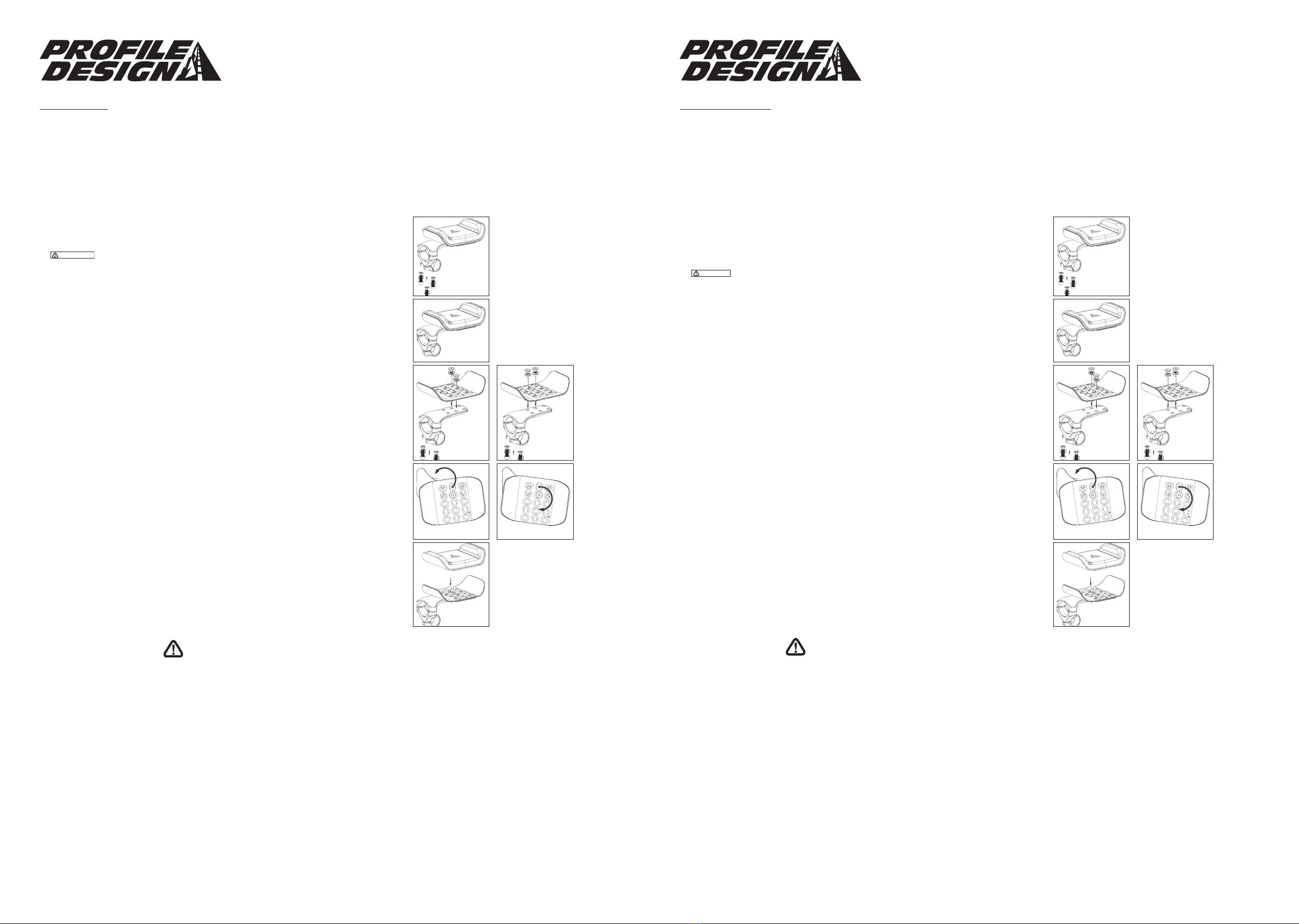
1. Extraiga los pernos M6 de la parte inferior de la abrazadera.
2. Coloque el soporte en la barra y conecte el soporte en “U” inferior en el soporte de la barra aerodinámica.
Enrosque los pernos a mano.
3. Ajuste el ancho y la inclinación de la barra a la posición deseada. Apriete de forma uniforme los pernos en 6 Nm (53 pulg-lbs).
No coloque los cables del freno o cambios entre el soporte de la barra aerodinámica y la barra base.
5. Coloque el apoyabrazos en la ubicación deseada del soporte. Inserte el perno M6 a través del apoyabrazos y en el
soporte. Utilizando la llave Allen de 4 mm, apriete el perno hasta que quede ajustado. Repita el procedimiento para el
segundo perno, dejándolo ligeramente ojo para permitir su ajuste.
NOTA: Los pernos pueden colocarse de lado a lado o de la parte frontal a la posterior para un posicionamiento
optimizado de los apoyabrazos.
6. Gire el apoyabrazos al ángulo preferido relativo a la extensión. Apriete de forma uniforme en 4,7 Nm (42 pulg-lbs).
7. Presione la almohadilla sobre el apoyabrazos y sostenga en esta posición durante 30 segundos.
Repita el mismo procedimiento para el otro apoyabrazos.
8. Vuelva a vericar si los tornillos están bien apretados luego del primer uso y periódicamente en lo consiguiente para
asegurar una jación del sistema de barra aerodinámica.
Herramientas y materiales necesarios: llave Allen de 4 mm, llave Allen de 5 mm y llave dinamométrica (pulg-lbs/Nm)
Las áreas roscadas han sido previamente tratadas por Prole Design durante la producción con un compuesto especial azul para sellado de roscas. Este compuesto especial es fácil
de detectar en las roscas de todos los tornillos proporcionados. Si usted no puede detectar este compuesto de sellado de roscas o si lo ha borrado por un mantenimiento regular,
vuelva a aplicar un compuesto azul de sellado de roscas apropiado disponible a la venta por Loctite u otra compañía antes de armarlo.
Outils et éléments requis : Clé Allen 4 mm, Clé Allen 5 mm et clé dynamométrique (po-lb/Nm)
Les zones letées ont été pré-traitées par Prole Design pendant la production avec un composé frein-let bleu spécial. Ce composé spécial est facile à détecter sur les lets de
tous les boulons fournis. Si vous ne pouvez pas détecter ce composé frein-let ou si vous l’avez enlevé pendant la maintenance normale, ré-appliquez un composé frein-let bleu
approprié, disponible auprès de Loctite ou d’un autre fournisseur avant l’assemblage.
• No seguir estas advertencias e instrucciones puede resultar en una rotura, deslizamiento y u otro mal funcionamiento
de este componente de Prole Design, lo que podría causar una pérdida de control de la bicicleta con daños graves.
[AP1100-1-1]
• Un componente que rechina puede ser un signo de problemas potenciales. Asegúrese que todas las supercies de
contacto entre los componentes estén limpias, que todas las roscas de los tornillos estén engrasadas o estén tratadas
con un sello de rosca apropiado y estén ajustadas según las especicaciones de Prole Design (o del fabricante
de la bicicleta) y que todos los componentes tengan el tamaño apropiado para adaptarse entre ellos. Si continúa
experimentando un rechinamiento deje de utilizar el componente de Prole Design y llame a servicio al cliente de
Prole Design. [AP0601-2-2]
• No apretar sucientemente un tornillo puede resultar en que una parte se aoje al montar y un tornillo excesivamente
apretado puede romper inesperadamente o estropear las roscas de engranaje al montar, lo que podría derivar
también en una pérdida del control. Todos los tornillos deben ajustarse de acuerdo a las especicaciones de torsión
de Prole Design (o del fabricante de la bicicleta). En el primer ensamblaje y cualquier ensamblaje subsiguiente,
verifique si hay roscas estropeadas o rajaduras en todas las roscas macho y hembras y alguna lubricación o
compuesto de sellado de rosca necesario. [AP1100-3-2]
• Examine periódicamente y de cerca todas las supercies de este componente de Prole Design (luego de limpiar)
contra la luz del sol para vericar si hay algún trazo no pequeño o fatiga en los "puntos de tensión" (como por
ejemplo soldaduras, junturas, agujeros, puntos de contacto con otras partes, etc.). Si usted ve alguna rajadura,
no importa que tan pequeño, deje de utilizar la parte inmediatamente y llame a servicio al cliente de Prole Design.
[AP0302-4-2]
• Siempre que instale algún nuevo componente en su bicicleta, asegúrese de probarlo detenidamente cerca de casa (con
su casco) en donde no haya obstáculos o tráco. Asegúrese de que todo esté funcionando apropiadamente antes de
salir a un paseo o a una carrera. [AP1100-5-1]
• Las carreras (de caminos, montañas o deportes múltiples) imponen una tensión extrema en las bicicletas y sus
componentes (así como también en los ciclistas) y acorta signicativamente su vida útil. Si participa en estos tipos de
eventos, el ciclo de vida del producto puede acortarse significativamente dependiendo del nivel y cantidad de
carreras. El "desgaste normal" de un componente puede diferir considerablemente entre usos competitivos y usos no
competitivos, y es por ello que los ciclistas de nivel profesional utilizan bicicletas y componentes nuevos cada
temporada así como también hacen que sus bicicletas sean mantenidas por mecánicos profesionales. Se debe tener
un especial cuidado en la evaluación regular de su bicicleta y sus componentes para asegurar su seguridad. [AP1100-6-1]
• Ciertos factores pueden reducir la vida de este componente a un tiempo menor a su período de garantía. El tamaño
del ciclista y/o fortaleza y estilo al andar, una gran cantidad de millas, terrenos duros, abuso, instalación inapropiada,
sudor, condiciones medioambientales adversas (como por ejemplo aire salino o lluvia corrosiva), daños en viajes
(especialmente si la bicicleta y los componentes se desarman y vuelven a armar repetidamente) y los choques o
accidentes pueden todos contribuir a acortar la vida de este componente. Mientras más factores estén presentes, más
se reduce la vida del componente. [AP0801-7-2]
• Asegúrese que el diámetro del área de aanzamiento del manubrio coincida con el diámetro de la abrazadera del
vástago (por ejemplo, 31,8 mm, 26,0 mm o 25,4 mm). Una coincidencia incorrecta podría resultar en un daño,
deslizamiento o rotura del manubrio y o del vástago, lo que podría causar una posible pérdida de control y daño.
[B0706-4-1]
• Los manubrios de bra de carbón exigen una atención y mantenimiento especial. Para la instalación de un vástago
con manubrios de bra de carbón reérase a las instrucciones del fabricante de los manubrios antes de la instalación.
[ST1100-1-1]
• Asegúrese de volver a vericar periódicamente la abrazadera posterior (jada al trinche) y la abrazadera delantera
(jada al manubrio) el ajuste del tornillo hexagonal (especialmente luego de montar en terrenos accidentados) para
asegurar una buena jación. [ST1100-2-1]
• Los trinches con tubos de dirección de bra de carbón exigen una atención y mantenimiento especial. Reérase a las
instrucciones del fabricante del trinche.
[ST1100-5-1]
4. Ajuste la rotación y la longitud de la extensión aojando el perno M6 que asegura a la extensión.
Una vez que se logre la rotación y longitud deseadas, apriete el perno M6 en 6 Nm (53 pulg-lbs).
• Prole Design garantiza todos sus productos durante dos años desde la compra original.
• Para mayores detalles sobre la garantía de Prole Design y la política de Reemplazo por accidentes,
visite www.prole-design.com/warranty
ADVERTENCIA
• Any failure to follow these warnings and instructions can result in breakage, slippage and or other malfunctioning of
this Prole Design component causing a loss of control of the bicycle with serious injuries. [AP1100-1-1]
• A creaking component can be a sign of potential problems. Make sure all contact surfaces between components are
clean, all bolt threads are greased or are treated with proper thread lock and tightened to Prole Design's (or the bike
manufacturers) specications and all components are properly sized to t together. If you continue to experience
creaking stop using the Prole Design component and call Prole Design customer service. [AP0601-2-2]
• Under tightening a bolt can result in a part coming loose while riding and an over tightened bolt can break
unexpectedly or strip the threads it is engaging while riding also resulting in a loss of control. All bolts must be
tightened to Profile Design's (or the bike manufacturer's) torque specifications. On the first and any subsequent
assembly examine all male and female threads and bolts for stripped threads, cracks and any required lubrication or
thread locking compound. [AP1100-3-2]
• Periodically, closely examine all surfaces of this Prole Design component (after cleaning) in bright sunlight to check
for any small hairline cracks or fatigue at "stress points" (such as welds, seams, holes, points of contact with other
parts etc.). If you see any cracks, no matter how small, stop using the part immediately and call Profile Design
customer service. [AP0302-4-2]
• Whenever you install any new component on your bike make sure you thoroughly try it out close to home (with your
helmet) where there are no obstacles or trafc. Make sure everything is working properly before going off on a ride or
to a race. [AP1100-5-1]
• Racing (road, mountain or multi-sport) places extreme stress on bicycles and their components (like it does riders) and
signicantly shortens their usable life. If you participate in these types of events, the lifetime of the product may be
signicantly shortened depending upon the level and amount of racing. The “normal wear” of a component may differ
greatly between competitive and non-competitive uses, which is why professional level riders often use new bikes and
components each season as well as having their bikes serviced by professional mechanics. Particular care should be
placed in the regular examination of your bicycle and it’s components to insure your safety. [AP1100-6-1]
• A number of factors can reduce the life of this component to less than its warranty period. Rider size and/or strength
and riding style, high mileage, rough terrain, abuse, improper installation, sweat, adverse environmental conditions (such
as salt air or corrosive rain), travel damage (especially if bike and components are repeatedly disassembled and then
reassembled) and crashes or accidents can all contribute to the shortening of the life of this component. The more
factors that are present, the more the life of the component is reduced. [AP0801-7-2]
• Make sure the handlebar clamp area diameter matches that of the stem clamp diameter (i.e. 31.8mm, 26.0mm or
25.4mm). An incorrect match could result in handlebar and or stem damage, slippage or breakage causing a possible
loss of control and injury. [B0706-4-1]
• Carbon fiber handlebars require special attention and maintenance. For installation of a stem with carbon fiber
handlebars please refer to handlebar manufacturer’s instructions prior to installation. [ST1100-1-1]
• Make sure you periodically recheck rear clamp (fork attachment) and front clamp (handlebar attachment) stem bolt
tightness (especially after riding on rough terrain) to insure a good attachment. [ST1100-2-1]
• Forks with carbon fiber steering tubes require special attention and maintenance. Refer to fork manufacturer’s
instructions. [ST1100-5-1]
• Prole Design gewährt auf sämtliche Produkte eine zweijährige Garantie ab Kaufdatum.
• Detaillierte Angaben zur Prole Design-Garantie und zum Austausch bei Stürzen/Unfällen
nden Sie hier: www.prole-design.com/warranty
1. Retirez les boulons M6 de la partie inférieure de l’attache.
2. Placez le support sur le cintre et connectez le support en U de la partie inférieure au support du prolongateur de guidon.
Vissez les boulons à la main.
3. Ajustez la largeur et l’inclinaison du cintre à la position souhaitée. Serrez uniformément les boulons M6 à 6 Nm (53 po.lb)
Ne faites pas passer les câbles des freins ou du dérailleur entre le support du prolongateur de
guidon et le cintre de base.
5. Placez le repose-bras en position préférentielle sur le support. Insérez le boulon M6 par le repose-bras et dans le support.
À l’aide de la clé Allen 4 mm, vissez le boulon jusqu’à ce qu’il soit bien serré. Répétez l’opération pour le deuxième boulon
en le laissant légèrement desserré pour permettre l’ajustement.
REMARQUE: Les boulons peuvent être installés côte à côte ou d’avant en arrière pour un positionnement
optimisé du repose-bras.
6. Faites pivoter le repose-bras jusqu’à l’angle préférentiel par rapport à l’extension.
Serrez uniformément à 4,7 Nm (42 po.lbs).
7. Appuyez le rembourrage contre le repose-bras et tenez-le fermement pendant 30 secondes. Répétez l’opération pour
l’autre repose-bras.
8. Vériez à nouveau le serrage des boulons après la première utilisation et périodiquement ensuite pour vous assurer de la
xation solide du système prolongateur de guidon.
1.、2.、3.1.、2.、3.
7.、8.7.、8.
4.4.
5.5.
6.6.
4. Ajustez la rotation et la longueur de l’extension en desserrant le boulon M6 xant l’extension.
Une fois la rotation et la longueur souhaitées déterminées, serrez le boulon M6 à 6 Nm (53 po.lb).

Other Profile Design Bicycle Accessories manuals

Profile Design Supersonic Ergo 35c User manual

Profile Design

Profile Design Supersonic Ergo 35c User manual

Profile Design Carbon X User manual

Profile Design

Profile Design Carbon X User manual

Profile Design Canta Zero User manual

Profile Design

Profile Design Canta Zero User manual

Profile Design Carbon X 1.5 User manual

Profile Design

Profile Design Carbon X 1.5 User manual

Profile Design HSF Aeria User manual

Profile Design

Profile Design HSF Aeria User manual

Profile Design RM 10 User manual

Profile Design

Profile Design RM 10 User manual

Profile Design DRV/GMR Series User manual

Profile Design

Profile Design DRV/GMR Series User manual

Profile Design HSF 800 HYDRATION User manual

Profile Design

Profile Design HSF 800 HYDRATION User manual

Profile Design Multi-Fit User manual

Profile Design

Profile Design Multi-Fit User manual

Profile Design T2+ DL User manual

Profile Design

Profile Design T2+ DL User manual

Profile Design A3a User manual

Profile Design

Profile Design A3a User manual

Profile Design F-25 Armrest Kit User manual

Profile Design

Profile Design F-25 Armrest Kit User manual

Profile Design CGT User manual

Profile Design

Profile Design CGT User manual

Profile Design ERGO+ ARMREST KIT User manual

Profile Design

Profile Design ERGO+ ARMREST KIT User manual

Profile Design DRV SIZER BAR User manual

Profile Design

Profile Design DRV SIZER BAR User manual

Profile Design 35SLC User manual

Profile Design

Profile Design 35SLC User manual

Profile Design Split Second User manual

Profile Design

Profile Design Split Second User manual

Profile Design Swiftshift User manual

Profile Design

Profile Design Swiftshift User manual

Profile Design WING20C+ User manual

Profile Design

Profile Design WING20C+ User manual

Profile Design Sonic CSX User manual

Profile Design

Profile Design Sonic CSX User manual

Profile Design RZ3 User manual

Profile Design

Profile Design RZ3 User manual

Profile Design RM Single System User manual

Profile Design

Profile Design RM Single System User manual

Profile Design Sonic Bracket User manual

Profile Design

Profile Design Sonic Bracket User manual

Profile Design 43ASC User manual

Profile Design

Profile Design 43ASC User manual

Popular Bicycle Accessories manuals by other brands

Bosch Kiox Original operating instructions

Bosch

Bosch Kiox Original operating instructions

Scott TWINLOC owner's manual

Scott

Scott TWINLOC owner's manual

Cateye MITY 3 user manual

Cateye

Cateye MITY 3 user manual

Shimano DEORE XT RD-M972 Technical Service Instructions

Shimano

Shimano DEORE XT RD-M972 Technical Service Instructions

Hovding 3 manual

Hovding

Hovding 3 manual

Norco KLICKfix quick start guide

Norco

Norco KLICKfix quick start guide

Polar Electro CS600X Getting started guide

Polar Electro

Polar Electro CS600X Getting started guide

UNIPRODO UNI_TRAILER_10 user manual

UNIPRODO

UNIPRODO UNI_TRAILER_10 user manual

motivation CHILDREN ACTIVE 3-WHEELER Assembly manual

motivation

motivation CHILDREN ACTIVE 3-WHEELER Assembly manual

Cateye CC-PA110W instructions

Cateye

Cateye CC-PA110W instructions

Cateye TWIN HL-NC250 instruction manual

Cateye

Cateye TWIN HL-NC250 instruction manual

SmartHalo SmartHalo user manual

SmartHalo

SmartHalo SmartHalo user manual

Magura MT2 owner's manual

Magura

Magura MT2 owner's manual

Yakima PlateMate Installation

Yakima

Yakima PlateMate Installation

Fidlock TWIST X KEEGO bottle 600 quick start guide

Fidlock

Fidlock TWIST X KEEGO bottle 600 quick start guide

ERGOTEC Stem Integra-BK installation guide

ERGOTEC

ERGOTEC Stem Integra-BK installation guide

XLC BS-C10 manual

XLC

XLC BS-C10 manual

SRAM FORCE user manual

SRAM

SRAM FORCE user manual

manuals.online logo
manuals.online logoBrands
  • About & Mission
  • Contact us
  • Privacy Policy
  • Terms and Conditions

Copyright 2025 Manuals.Online. All Rights Reserved.