Evocare GLS5 User manual


2
© Guldmann GB/US-1971/06/2013 • # 554510
© Guldmann GB/US-1971/06/2013 • # 554510
© Guldmann GB/US-1971/06/2013 • # 554510
© Guldmann GB/US-1971/06/2013 • # 554510
GLS5Activelifter
Itemnos:
556-xxx
100Manufacturer3
200Intendeduse3
2.01 .........Where to use GLS5 ............................................3
300Denitions4
400UseofActivelifter5
4.01 ........Warning ......................................................5
4.02 ........Safety precautions ..............................................6
4.03 .........Checklist before use ............................................6
500Operation7
5.01 ........Safety functions ................................................8
5.02 ........Important .....................................................9
600Howtousethesling10
700 Chargingprocedure 14
800 Unpackingandpreparationofthelifter 14
8.01 . . . . . . . . Charging and installing battery . . . . . . . . . . . . . . . . . . . . . . . . . . . . . . . . . . . 14
900Troubleshooting15
1000 Methodofcleaninganddisinfection 16
1100Serviceandlifespan16
1200 Transportationandstorage 17
1300Technicalspecications18
13.01 . . . . . . . Indicator lamps and audio signals . . . . . . . . . . . . . . . . . . . . . . . . . . . . . . . . . 21
1400Labelling22
1500 EC-Declarationofconformity 24
1600 Environmentalpolicystatement-VGuldmannA/S 25
USAandcountriesoutsidetheEU 26
A. ...........Users guide ..................................................26
B. ..........WARRANTY ..................................................26

3
© Guldmann GB/US-1971/06/2013 • # 554510
© Guldmann GB/US-1971/06/2013 • # 554510
© Guldmann GB/US-1971/06/2013 • # 554510
© Guldmann GB/US-1971/06/2013 • # 554510
100 Manufacturer
V. Guldmann A/S.
Graham Bells Vej 21-23A
DK - 8200 Aarhus N
Tlf. +45 8741 3100
Fax. +45 8741 3131
200 Intendeduse
GLS5 is a mobile active lifter which is designed to assist the user from a
sitting to a standing position. It can also be used to assist the user in the
toileting procedure or the beginning of the rehabilitation process. The lifter is
suitable for lifting or moving a person who is capable of actively participating
in the process, the user must also have good communication skills.
When the active lifter is used the assumption is that:
• The user can balance in a sitting position, has strength in the lower and upper
body and can communicate.
• The lifter will be operated by a qualied person.
• The active lifter is moved at a maximum speed corresponding to normal
walking speed.
• The Guldmann active lifter is used with Guldmann lifting slings.
Guldmann cannot be held responsible for any faults or accidents that may
occur due to incorrect positioning of the lifting sling, nor for inadequate atten-
tion paid by the helper. We strongly recommend assessment of the user
before every lift.
201 WheretouseGLS5
GLS5 is designed to be used in hospitals, nursing homes, institutions and
private homes. It can be used indoors whenever the user needs to be lifted or
moved on a level surface.
• The lifter is designed so its legs can t under beds, around chairs / wheel-
chairs.
• The lifter can be used in wet areas however, it must not be exposed to splash
water.
• The lifter is designed to be used with multiple users. When moving the lifter to
another user / ward / room, perform normal hygienic disinfection.

4
© Guldmann GB/US-1971/06/2013 • # 554510
© Guldmann GB/US-1971/06/2013 • # 554510
© Guldmann GB/US-1971/06/2013 • # 554510
© Guldmann GB/US-1971/06/2013 • # 554510
300 Denitions
1. Sling attachment hooks
2. Lifting boom
3. Hip support sling attachment
4. Battery
5. Electronic control box
6. Hand control
7. Emergency stop
8. Emergency lowering
electrical
9. Emergency lowering
manual
10. Push handle
11. Calf strap
12. Knee pad
13. Power supply
14. Lifting actuator
15. Knee pad height
adjustment knob
16. Knee pad length
adjustment knob
17. Foot plate
18. Chassis leg
19. Brake/release
20. Foot bar
10
4
6
13
14
17
18
7
20
5
8
9
12
15
16
19
11
2
1
1
3

5
© Guldmann GB/US-1971/06/2013 • # 554510
© Guldmann GB/US-1971/06/2013 • # 554510
© Guldmann GB/US-1971/06/2013 • # 554510
© Guldmann GB/US-1971/06/2013 • # 554510
400 UseofActivelifter
The lifter is designed to lift from a sitting position only. It is NOT designed to
lift from lying position.
Before using the lifter we strongly recommend that a full risk assessment
is carried out by a qualied person to ensure the user capability, the cor-
rect slings are used and the environment is suitable. Anyone using the lifter
should be fully trained on its use.
Before every transfer with the active lifter, we strongly recommend you carry
out a quick assessment to assess the user’s capability.
QuickAssessment
With the user in a seated position in chair / wheelchair / edge of bed - ask
the user to push down through his/her knees (feet must be placed at on the
oor) - upon inspection the helper should see the user’s quads tighten. This
indicates strength to assist with the standing procedure, it also conrms com-
munication skills.
401 Warning
Read the user manual fully before using the lifter.
• Do not exceed the max. load.
• Use the lifter to lift a person only.
• Use the lifter on an even and level surface only.
• When adjusting the legs of the lifter make sure that no persons stand close to
the legs due to the risk of being jammed.
• Do not run the lifter into persons or objects.
• Exchange of lifting motor/actuator according to the manufacturer’s instruc-
tions. See service chapter
• In case of damage, do not use the lifter until authorized by qualied service
staff or the Guldmann service team.
• Do not use the lifter in areas where it can be splashed with water.

6
© Guldmann GB/US-1971/06/2013 • # 554510
© Guldmann GB/US-1971/06/2013 • # 554510
© Guldmann GB/US-1971/06/2013 • # 554510
© Guldmann GB/US-1971/06/2013 • # 554510
402 Safetyprecautions
• Risk of entrapment between the top of the lifting actuator and lifting arm.
• Risk of entrapment between the legs and the chassis when adjusting the
legs.
403 Checklistbeforeuse
• The lifter must be off charge.
• Check the lifter is lifting and lowering and the legs are opening and closing, if
you hear the audio warning (a beeping sound) DO NOT USE THE LIFTER –
it needs to be charged.
• Check that the green light located on the control box is illuminated when the
lifter is activated.
• Check that the emergency stop and lowering is working.
• Make sure the lifter is running freely.
• Check the slings for damage or fraying.
Once you have tted the sling (see section 6.00 - How to use the sling) you
are ready to lift.
Withtheuserinaseatedposition
• If the user is in a wheelchair or commode chair the brakes must be applied.
• Position the lifting boom at lowest position and introduce the lifter square onto
the user. The helper should be positioned at the side of the lifter (to ensure
the lifter does not run over the user’s feet).
• Open the lifter’s chassis leg width adjustment to allow access around the
chair.
• Position the user’s feet at onto the foot plate and adjust the knee pad - the
top of the knee pad should be level with the top of the shin, two ngers below
the knee joint.
• OPTIONAL – if the user has a tendency to have involuntary movements you
can use the calf strap to ensure the users’ feet do not come off the foot plate.
If the calf strap is not in use, fasten the strap to the back of the knee pad
(avoiding loose straps).
Fig2
Fig1

7
© Guldmann GB/US-1971/06/2013 • # 554510
© Guldmann GB/US-1971/06/2013 • # 554510
© Guldmann GB/US-1971/06/2013 • # 554510
© Guldmann GB/US-1971/06/2013 • # 554510
• Raise the lifting boom to gain tension on the sling - ENSURE THE SLING IS
STILL SECURE AND ATTACHED BEFORE CONTINUING WITH THE LIFT.
Communication should be maintained throughout the lifting procedure.
Alternatively you have the option to attach the sling onto the lower hooks; this will
facilitate an alternative lifting position and is more suitable for the shorter user.
To lower the user back into a seated position push the lifter up to the chair
/ commode chair / toilet and position the user so the calf is parallel to the
chair / commode chair / toilet. Begin to lower and ask the user to push his/her
pelvis / hip backwards to ensure the correct seated position.
• Release the sling straps and move the lifter away from the user.
• The sling is ready for removal - see sling user guide.
WorkingwiththeActivelifter
• Always maintain a good working posture when applying the sling or working
with the lifter. When moving a person use the push handle and walk with the
lifter keeping the load as close as possible to your body. NEVER pull or twist
at arm’s length, this can cause injury to the helper.
500 Operation
To lift/lower and adjustment of chassis leg in/out
• To lift the patient press UP arrow and to lower
the patient press DOWN arrow on the hand
control or the control box.
• On GLS5 active lifter the leg spread width
adjustment of the chassis is operated via the
sideways arrows on the hand control or the
control panel on the control box.
• Use max. width setting when lifting to/from
wide chairs, or as necessary when lifting to/
from bed, toilet and chair.
• The hand control is designed to be parked at
the lifting boom.
• When maneuvering the lifter the chassis legs
must be in the closed narrow position.

8
© Guldmann GB/US-1971/06/2013 • # 554510
© Guldmann GB/US-1971/06/2013 • # 554510
© Guldmann GB/US-1971/06/2013 • # 554510
© Guldmann GB/US-1971/06/2013 • # 554510
501 Safetyfunctions
Only use the emergency stop button and
emergency lowering functions in emergencies.
If it has been necessary to apply the emer-
gency/safety functions due to an error on the
lifter, the supplier must be contacted prior to
using the lifter again.
Activatingtheemergencystopfunction
Should the lifter not respond to the functions selected on the hand control
when it is in motion, press emergency stop. When the emergency stop func-
tion is applied, the lifter ceases to function. Switch the lifter on again by turn-
ing the emergency stop button in the direction of the arrow until it jumps out.
Activatingtheemergencyloweringfunction
If the lifter fails to lower, activate the following:
1. Press the emergency lowering button on the
control box display
If the lifting boom does not lower
2. Turn the red knob in the direction of the arrow
Useofbrakes
The rear castors are tted with brakes. Apply
the brake by stepping on the lower kick pedel.
To release the brake, kick the top part of the
kick pedal.
Only apply the brakes if the user is pushing
the lifter away with his/her feet on the foot
plate while the user is seated in the chair,
wheelchair, toilet or commode.

9
© Guldmann GB/US-1971/06/2013 • # 554510
© Guldmann GB/US-1971/06/2013 • # 554510
© Guldmann GB/US-1971/06/2013 • # 554510
© Guldmann GB/US-1971/06/2013 • # 554510
Useoffootbar
The foot bar is there to assist the helper to
initiate movement, and to facilitate the clear-
ing of door thresholds or to assist loading into
vehicles. This is achieved by placing one foot
onto the foot bar and gently pulling back on
the push handle.
Adjustmentofkneepad
The knee pad can be adjusted in vertical and
horizontal direction to t the different users.
Vertical:Adjust by unscrew the yellow knob,
lift or lower the knee pad in right position and
then tighten the knob.
Horizontal: Loosen the yellow knob, then
slide the knee pad in or out until it ts the user.
Then tighten the knob clockwise to lock the
knee pad safely.
502 Important
• Read the user manual and familiarize yourself with the controls and safety
features on the lifter.
• Always plan your lift before commencing.
• Only use slings that are designed to be used with the active lifter.
• Never use slings that are damaged, frayed or have unreadable labels.
• Check to make sure the user does not exceed the safe working load of the
lifter.
• For safety reasons we DO NOT recommend transporting users through
standard door frames.
• Caution must be exercised when mounting the sling lifting straps onto the
lifting hooks of the boom.

10
© Guldmann GB/US-1971/06/2013 • # 554510
© Guldmann GB/US-1971/06/2013 • # 554510
© Guldmann GB/US-1971/06/2013 • # 554510
© Guldmann GB/US-1971/06/2013 • # 554510
600 Howtousethesling
StandingSling
NOTE: Label must be facing away from the user and must not be turned
upside down.
1. Place the sling on the user’s shoulders and
/ or the chair’s backrest. Ask the user to
lean forward and let the sling go behind the
user’s back positioning the sling two ngers
beneath the shoulder blade and above the
belt line.
2. Position the upper edge of the sling under
the armpits and stand in front of the user.
Ensure that a minimum distance of two n-
gers is between the sling and the armpits.
Ensure the belt is securely tightened and the
Velcro is functional.
3. Wrap and attach the support belt rmly
around the upper body to prevent the sling
from sliding. The sling is now ready for
attachment to the lifter.
4. Introduce the lifter. CAUTION must be exer-
cised to the foot plate when near user’s feet.
Place the user’s feet onto the foot plate and
adjust the knee pad - the top of the knee pad
should be level with the top of the shin on a
distance of two ngers below the knee joint.
OPTIONAL – if the user has a tendency to
have involuntary movements you can use
the calf strap to ensure the user’s feet do
not come off the foot plate. If the calf strap is
not in use fasten the strap to the back of the
knee pad (avoiding loose straps).

11
© Guldmann GB/US-1971/06/2013 • # 554510
© Guldmann GB/US-1971/06/2013 • # 554510
© Guldmann GB/US-1971/06/2013 • # 554510
© Guldmann GB/US-1971/06/2013 • # 554510
5. Raise the lifting boom to gain tension on the
sling - ENSURE THAT THE SLING IS STILL
SECURE AND ATTACHED BEFORE CONTI-
NUING WITH THE LIFT.
Communication with the user should be
maintained throughout the lifting procedure.
Alternatively you have the option to attach
the sling onto the lower hooks; this will facili-
tate an alternative lifting position and is more
suitable for the shorter user.
When placing the user back into a seated
position push the lifter up to the chair / com-
mode chair / toilet and position the user so
the user’s calf is parallel to the chair / com-
mode chair / toilet. Begin to lower and ask
the user to push his/her pelvis backwards to
ensure the correct seated position.
To remove the sling carry out the tting
instructions in reverse order, taking care to
remove the sling from the user avoiding skin
friction and movement.
HipSupportSling
Attachmentofthehipsupportstraps
The support straps are looped at one end
and have a buckle at the other. Thread the
looped end through the gate on the boom
and attach over the push handle bar as seen
in the gure below. The strap is ready for
use.

12
© Guldmann GB/US-1971/06/2013 • # 554510
© Guldmann GB/US-1971/06/2013 • # 554510
© Guldmann GB/US-1971/06/2013 • # 554510
© Guldmann GB/US-1971/06/2013 • # 554510
HipSupportSlingwiththeStandingSling
NOTE: Label must be facing away from the
user
1. Before tting the standing sling ask the user
to lean forward and introduce the hip support
sling. This should be positioned at the base
of the spine either side of the hips. Fit the
standing sling as previously described.
2. Introduce the lifter. CAUTION must be exer-
cised to the foot plate when near user’s feet.
Place the user’s feet onto the foot plate and
adjust the knee pad - the top of the knee pad
should be level with the top of the shin two
ngers below the knee joint.
OPTIONAL – if the user has a tendency to
have involuntary movements you can use
the calf strap to ensure the user’s feet do
not come off the foot plate. If the calf strap is
not in use fasten the strap to the back of the
knee pad (avoiding loose straps).
3. Attach the hip support sling to the straps
snapping the buckle together. Raise the
lifting boom to gain tension on both slings
– ENSURE THAT THE SLING IS SECURE
AND ATTACHED BE FORE CONTINUING
WITH THE LIFT. Adjust the hip support
straps through the buckle and continue. The
hip support sling should tension before the
standing sling, - if it does not, then lower the
user and readjust one or both slings.

13
© Guldmann GB/US-1971/06/2013 • # 554510
© Guldmann GB/US-1971/06/2013 • # 554510
© Guldmann GB/US-1971/06/2013 • # 554510
© Guldmann GB/US-1971/06/2013 • # 554510
4. As the lift progresses at approximately 60%
into the standing procedure the hip support
sling will loosen and once in standing the
sling will be redundant allowing access to
lower garments. Communication should be
maintained throughout the lifting procedure.
Alternatively you have the option to attach
the standing sling onto the lower hooks, this
will facilitate an alternative lifting position and
is more suitable for the shorter user.
When placing the user back into a seated
position push the lifter up to the chair /com-
mode chair/toilet and position the user so
his/her calf is parallel to the chair /commode
chair/toilet.
5. Begin to lower and at approximately 40%
into the lowering procedure re-apply the hip
support sling and continue to lower. The sling
will ensure correct seated position.
To remove the sling carry out the tting
instructions in reverse order, taking care to
peel the sling away from the user avoiding
skin friction and movement.
Alternatively: The Active Micro Plus sling
can be used with the active lifter – for
instructions see separate user guide for
Active Micro Plus Sling.
14
© Guldmann GB/US-1971/06/2013 • # 554510
© Guldmann GB/US-1971/06/2013 • # 554510
© Guldmann GB/US-1971/06/2013 • # 554510
© Guldmann GB/US-1971/06/2013 • # 554510
700 Chargingprocedure
Recharge lifter every night or when it is not in
use. This maintains the batteries and ensures
a long life span.
Only use power supply provided by Guldmann.
Recharging
• Recharge by plugging the power supply lead into the wall socket
• Recharging must be carried out when the yellow, or red LED is illuminated
• When the yellow LED illuminates there are approx. 10 lifts remaining
• When the red LED illuminates and the audio warning sounds, it is only pos-
sible to lower the patient
• The power supply will turn off automatically when lifter is fully recharged
• Recharging must not take place in wet rooms/bathrooms
• Max. recharging time is approx. 5 hours.
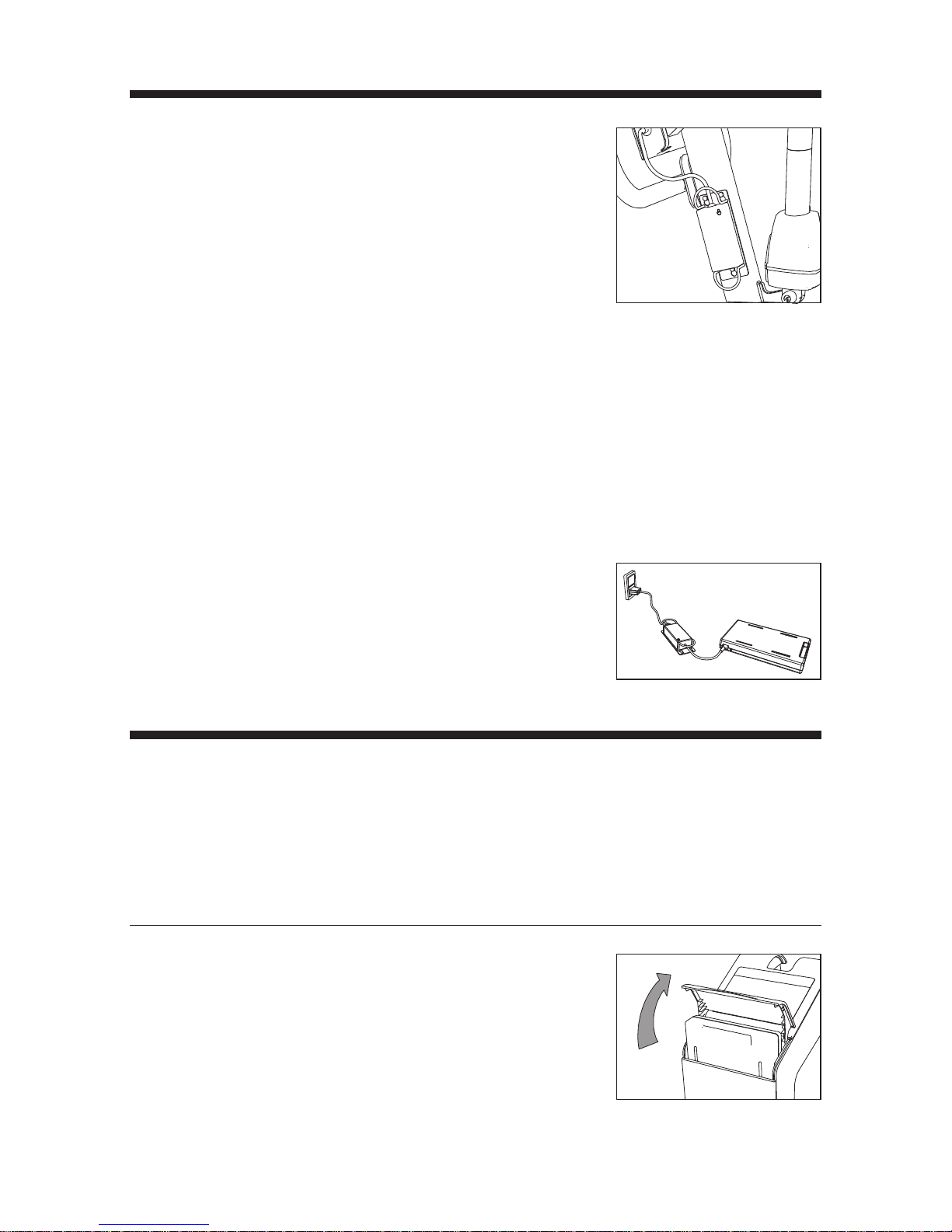
Alternativechargingprocedure
Remove the battery and place it on a dry
surface. Connect power supply plug to mains.
Now insert the male connector into battery.
800 Unpackingandpreparationofthelifter
Visualcheckoflifter
If the packaging is damaged on receipt, each part of the lifter must be careful-
ly examined for visible defects or deciencies. In case of suspected damage,
do not use the lifter until authorized by qualied service staff or the Guldmann
Service Team.
801 Chargingandinstallingbattery
Before use, the battery needs to be fully
charged. See charging procedure.
Unpack the battery from its packaging and
locate into battery compartment by opening
the lid and sliding it into position.

15
© Guldmann GB/US-1971/06/2013 • # 554510
© Guldmann GB/US-1971/06/2013 • # 554510
© Guldmann GB/US-1971/06/2013 • # 554510
© Guldmann GB/US-1971/06/2013 • # 554510
900 Troubleshooting
Error:
Lifter does not react to input from the buttons on the hand control.
1 DoesthegreenoryellowLEDilluminateonthelifterwhenthecontrol
buttonsonthehandcontrolareactivated?
Yes see point 6.
No no light visible – see point 2.
No only red light visible – see point 3.
No yellow service light visible or audible “Beep”– see “indicator and audio
signals matrix” point 13.01.
2 Isthebatteryinstalledinthelifter?
Yes see point 4.
No install a fully charged battery.
3 Isabatterywithsufcientchargeinstalledinthelifter?
No install a fully charged battery.
4 Istheemergencystopactivated?
Yes turn emergency stop in the direction of the arrow to allow it to release
and press any button on the hand control.
No see point 5
5 Istheconnectorforthehandcontrolttedinthelifter,andisthelifter
reactingtothebuttonslocatedonthecontrolbox?
Yes replace hand control
No t connector
6 Aretheconnectorsfortheliftingmotorand/orlegadjustmentmotor
tted?
Yes see point 5
No t connector
Contact the Guldmann Service Team if the fault cannot be found and
corrected.

16
© Guldmann GB/US-1971/06/2013 • # 554510
© Guldmann GB/US-1971/06/2013 • # 554510
© Guldmann GB/US-1971/06/2013 • # 554510
© Guldmann GB/US-1971/06/2013 • # 554510
1000 Methodofcleaninganddisinfection
Cleaning
We recommend that any parts of the active lifter that users/helper may come
in contact with are cleaned with Novadan Des Wipes, Novadan Desinfect O
or similar disinfection product.
DesinfectO:
A broad-spectrum disinfectant system as tablets. Suitable for disinfection of
equipment, tools and surfaces in the healthcare sector.
NovadanDesWipes:
Use a disposable wipe for cleaning and disin-
fection of all types of surfaces, machines and
instruments in the healthcare sector.
NB:Do never clean the lifter with strong acid,
base or alcohol. Never clean the lifter in an
autoclave machine.
For easier cleaning of the foot plate it can be
lifted off.
The grey inserted plate can be removed sepa-
rately for cleaning. Footplate and grey insert
plate can be cleaned using hot water and dis-
infecting soap.
1100 Serviceandlifespan
According to the international standard EN/ISO 10535 “Lifter for the transfer
of disabled persons - Requirements and test methods” a safety inspection of
the lifter must be performed at least once a year.
The lifter has an expected lifespan of 15
years. The lifespan is estimated on the basis
of correct use, cleaning and maintenance, plus
annual service and maintenance carried out by
qualied service engineers of the Guldmann
Service Team. At the end of the expected
life span, the lifter must then be assessed by
qualied service staff as to the lifters future
use. The lifespan of the lifting actuator is deter-
mined by how regular the lifter is used.

17
© Guldmann GB/US-1971/06/2013 • # 554510
© Guldmann GB/US-1971/06/2013 • # 554510
© Guldmann GB/US-1971/06/2013 • # 554510
© Guldmann GB/US-1971/06/2013 • # 554510
Guldmann active lifter has intelligent monitoring of the usage pattern. The
control box monitors the numbers of lifts and duration of the lifts. The service
light on the control panel will then indicate when the lifting actuator needs
replacing. This means that the lifespan of the actuator is dependent on the
usage pattern of the lifter.
Thelifespanoftheliftingactuator-examples
Lifts/day Userweight–85kg/187lbs Userweight–120kg/243lbs
Lifespan lifting actuator Lifespan lifting actuator
5 17 years 15 years
20 4.5 years 4 years
The lifter is controlled by a microprocessor PC board which can be damaged
if it is being touched without the necessary precautions. Therefore the elec-
tronics must only be serviced by qualied Guldmann Team.
Spare parts lists and drawings are available from manufacturer or supplier.
1200 Transportationandstorage
The lifter can be dismantled for transport and storage.
1. Remove the electrical cable to the base from
the control box.
2. Loosen the knob and lift the mast from the
base.

18
© Guldmann GB/US-1971/06/2013 • # 554510
© Guldmann GB/US-1971/06/2013 • # 554510
© Guldmann GB/US-1971/06/2013 • # 554510
© Guldmann GB/US-1971/06/2013 • # 554510
Howtopackthelifterfortransport
Guldmann recommends that the dismantled lifter is always transported in its
original packaging.
Storageofactivelifter
The active lifter should be stored in a dry room, where the humidity does not
exceed 70%. The active lifter must never be stored in bathrooms and similar
areas.
Always activate emergency stop when the active lifter is put on storage.
Howtoprevent/avoidcorrosion
The active lifter should not be stored/remain in damp surroundings for long
periods of time. Water vapor might liquefy into water on the active lifter, thus
causing corrosion/rust in bearings as well as in the tubular steel frame.
The active lifter should not be exposed to sudden cold or warmth. This means
that one should not take a cold active lifter into a hot bathroom. In swimming
baths and bathrooms where strong gases may be present, the active lifter is
particularly exposed to corrosion and should always be removed from such
places after use.
1300 Technicalspecications
Functions
Lifting capacity, max: . . . . . . . . . . . . . . . . . . . . . . . . . . . . . . . . . . .155/205 kg
Operation
Lift: ....................................................Electric
Width adjustment: .........................................Electric
Pushbuttons - max.: ........................................ 3.3 N
Knee pad: ...............................................Manual
Lifting boom: .............................................Manual
Weight
Totally: ...................................................56 kg
Chassis without foot plate & knee pad: . . . . . . . . . . . . . . . . . . . . . . . . . 23 kg
Mast and lifting boom incl. control box & battery: . . . . . . . . . . . . . . . . . . 22 kg

19
© Guldmann GB/US-1971/06/2013 • # 554510
© Guldmann GB/US-1971/06/2013 • # 554510
© Guldmann GB/US-1971/06/2013 • # 554510
© Guldmann GB/US-1971/06/2013 • # 554510
Measurements
A: . . . . . . . . . . . . . . . . . . . . . . . . . . . . . . . . . . . . . . . . . . . . . . . . . . . . . . 25 mm
B: . . . . . . . . . . . . . . . . . . . . . . . . . . . . . . . . . . . . . . . . . . . . . . . . . . . . . . 90 mm
C: ...................................................1770 mm
D: ................................................... 1190 mm
E: . . . . . . . . . . . . . . . . . . . . . . . . . . . . . . . . . . . . . . . . . . . . . . . . . . . . . 575 mm
F: ....................................................1210 mm
G: ....................................................460 mm
H min/max: .........................................850/1740 mm
I min/max: ...........................................350/450 mm
J min/max: .........................................560/1190 mm
K min/max: .........................................670/1310 mm
L min/max: ..........................................230/320 mm
Turningradius
Turning radius : .........................................1295 mm
SafetyFeatures
Battery protection for insufcient voltage: . . . . . . . . . . . . . . . Yes, disconnects
Electricalparts
On/off: .............................................Automatically
Power supply for charging
Input: . . . . . . . . . . . . . . . . . . . . . . . . . . . . . .100-240Vac, 47-63Hz, 0.6-0.4A
Output: .............................................36V, 0.83A
Battery, replaceable NiMH: . . . . . . . . . . . . . . . . . . . . . . . . . . . . . . 24V /4.5 Ah
Charging time: ......................................Max. 5 hours
Consumption/power of actuator: . . . . . . . . . . . . . . . . . . . . . . . . . .24V, max 8A
Duty Cycle: . . . . . . . . . . . . . . . . . . . . . . Max 10%, max. 2 min on, 18 min off.
Classoftightness
Active lifter: ............................................... IP 32
Hand control: ............................................. IP 44
Power supply: ............................................. IP 20
Labelling
The product is manufactured in compliance with the Council Directive
93/42/EEC of June 14th 1993, including amendments, as medical device
class 1.
Classied
Acc. to ISO 9999: ........................................12 36 03

20
© Guldmann GB/US-1971/06/2013 • # 554510
© Guldmann GB/US-1971/06/2013 • # 554510
© Guldmann GB/US-1971/06/2013 • # 554510
© Guldmann GB/US-1971/06/2013 • # 554510
E
L
A
H
B
C
700
D
115
F
I
180
J
K
G
E
L
A
H
B
C
700
D
115
F
I
180
J
K
G
Table of contents
Popular Lifting System manuals by other brands

Terex
Terex Genie GRC-12 operators manual with maintenance information

Reechcraft
Reechcraft PowerLift PL52 Operators safety manual

matev
matev FPS Mounting Assembly Installation Guide

Mortuary Lift
Mortuary Lift ULTIMATE 1000 instructions

Ravaglioli
Ravaglioli KP 1396 E manual

Upright
Upright SL20 Series Operator's manual


