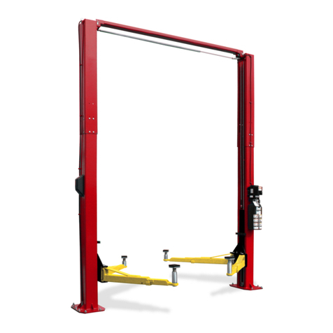
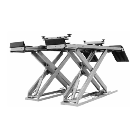
John Bean JLT4500S User manual

1
I NSTALLATION, O PERATION & M AINTENANCE M ANUAL
Two Po st S u rfa ce M o u n ted Lif t
M ODELS
J L T 4 5 0 0 S
J L T 4 5 0 0 T
4 5 0 0 k g c a p a c i t y
S n a p - on Eq uipment E u r op e
Vi a P r o . C a r p i , 33
4 2 0 1 5 Co r r e g g i o ( R E ) - I TA LY
FAX: +39 0522/733-479
Phone: +39 0522/733-480
Web Site: www.snapon-equipment.eu
Original Instructions
Voltage Frequency Phases Power
400 V 50 Hz PH 4.0 kW
2 0 V 50 Hz 1 PH 4.0 kW

REV 02 OCT 2020 JLT4500-IOM-F
2
Manufacturer Snap-on Equipment Hungary Kft.
Address
European address:
Snap-on Equipment Hungary Kft.
H-9400 Sopron
Somfal i u. 13.
Phone: +36-99-311-206
Fax:
+36
-
99
-
312
-
232
Type of machine Passenger car and light truck 2 post lift
Type
JLT
4500
Model(s)
JLT
4500S
/
JLT
4500T
Manufacturing year 2020
Snap-on Equipment
Warranty & Liability

REV 02 OCT 2020 JLT4500-IOM-F
3

REV 02 OCT 2020 JLT4500-IOM-F
4
CONTENT
1 FOREWORD...............................................................................................................................................................................................5
2 GENERAL SAFETY AND ACCIDENT-PREVENTION RULES....................................................................................................................5
3 WORKPLACE ENVIRONMENT..................................................................................................................................................................6
4 RESIDUAL HAZARDS................................................................................................................................................................................7
4.1 CRUSHING HAZARD......................................................................................................................................................................8
4.2 HAZARD OF THE VEHICLE TO FALL FROM THE LIFT .................................................................................................................9
4. HAZARD OF OVERTURNING OF THE VEHICLE DUE TO INSTABILITY OF THE LOAD...............................................................9
4.4 ELECTRIC HAZARD.....................................................................................................................................................................10
4.5 GENERIC HAZARDS....................................................................................................................................................................10
4.6 EMERGENCY STOP..................................................................................................................................................................... 11
5 JLT4500 TWO POST LIFT........................................................................................................................................................................12
5.1 DESCRIPTION OF THE LIFT........................................................................................................................................................12
5.1.1 LAYOUT: ...........................................................................................................................................................................14
5.1.2 IDENTIFICATION AND CE MARKING LABEL:..................................................................................................................14
5.1. FORECASTED USE: ........................................................................................................................................................14
5.2 INSTALLATION: ............................................................................................................................................................................15
5.2.1 PACKING TYPE, SHIPPING, HANDLING, HOISTING POINTS ........................................................................................15
5.2.2 STORAGE ........................................................................................................................................................................16
5.2. UNPACKING.....................................................................................................................................................................16
5.2.4 FOUNDATION...................................................................................................................................................................16
5. ASSEMBLY ...................................................................................................................................................................................17
5. .1 AUTHORISED PERSONNEL ............................................................................................................................................17
5. .2 NEEDED TOOLS ..............................................................................................................................................................17
5. . INSTALLATION.................................................................................................................................................................18
5. .4 ADDITIONAL INFORMATION ON THE HYDRAULIC CIRCUIT: ........................................................................................ 5
5.4 OWNER/EMPLOYER’S RESPONSABILITIES .............................................................................................................................. 6
5.5 USE .............................................................................................................................................................................................. 6
5.5.1 LOADING OF VEHICLES.................................................................................................................................................. 7
5.5.2 OPERATING THE LIFT..................................................................................................................................................... 8
5.5. LOWERING A VEHICLE ................................................................................................................................................... 9
5.5.4 SAFETY PRECAUTIONS DURING THE USE:.................................................................................................................. 9
5.6 MAINTENANCE ............................................................................................................................................................................ 9
5.6.1 PERIODIC CHECKS:........................................................................................................................................................40
5.6.2 SPECIFIC CHECKS:.........................................................................................................................................................41
5.6. HYDRAULIC OIL RECOMMENDED. ................................................................................................................................42
5.6.4 CLEANING:.......................................................................................................................................................................42
6 DISMANTLING OF THE LIFT AND SCRAPPING.....................................................................................................................................43
7 TECHNICAL ASSISTANCE ......................................................................................................................................................................43
8 TROUBLE SHOOTING .............................................................................................................................................................................43
9 SPARE PARTS: GENERAL INSTRUCTIONS...........................................................................................................................................45
9.1 PARTS BREAKDOWN OF FINAL ASSEMBLY ..............................................................................................................................46
GB/T 6177.1-2000 M6 NUT..........................................................................................................................................................................47
HEX BOLT GB/T5789-2000 M6x16 .............................................................................................................................................................47
9.2 PARTS BREAKDOWN OF OVERHEAD ASSEMBLY ....................................................................................................................48
9. PARTS BREAKDOWN OF PARTS ON COLUMNS .......................................................................................................................49
ELECTROMAGNER BRACKET ..................................................................................................................................................................50
GB/T882-2008 5×38×1.2×35........................................................................................................................................................................50
BUSHING.....................................................................................................................................................................................................50
GB/T 879.1-2000 6X35 ................................................................................................................................................................................50
9.4 PARTS BREAKDOWN OF HYDRAULIC SYSTEM........................................................................................................................51
TEE FITTING ...............................................................................................................................................................................................51
90 DEG SWIVEL ELBOW, M14 ...................................................................................................................................................................51
4.5T 2-POST HYD, HOSE ASSY, RS...........................................................................................................................................................51
9.5 PARTS BREAKDOWN OF SYNCHRONIZING SYSTEM...............................................................................................................52
9.6 PARTS BREAKDOWN OF CARRIAGE AND ARMS......................................................................................................................54
10 SAFETY PICTOGRAMS ON THE LIFT...................................................................................................................................................56
11 INITIAL CHECK LISTS ...........................................................................................................................................................................58
11.1 CHECK PROCEDURE FOR LIFT................................................................................................................................................58
11.2 ANNUAL CHECKS ......................................................................................................................................................................59
12 ELECTRICAL DIAGRAM........................................................................................................................................................................65
12.1 WIRING DIAGRAM FOR THREE PHASES (SHEET 1/ ) ............................................................................................................65
12.2 WIRING DIAGRAM FOR SINGLE PHASE (SHEET 2/ ) .............................................................................................................66
12. WIRING DIAGRAM OF CONTROL BOXES (SHEET / )............................................................................................................67
12.4 WIRING DIAGRAM OF THE ELECTRICAL SYSTEM..................................................................................................................68
12.5 ELECTRICAL PARTS OF MAIN CONTROL BOX........................................................................................................................69
13 FOUNDATION PLAN ..............................................................................................................................................................................70
REV 02 OCT 2020 JLT4500-IOM-F
5
CAUTION
This document is the exclusi e property of Snap-on Incorporated which forbids its reproduction, either in part or wholly, without its
explicit appro al in writing.
WARNING
Only permit trained and authorized persons to perform maintenance/operate this equipment.
Any person authorized to operate the lift shall be gi en copy of the manual; the owner of the lift shall make sure that any person
authorized to use the lift has fully read and understood the present manual, therefore knowing how to use the lift in safe conditions.
Safe use is guaranteed only by clearly following the instructions listed in this manual, especially for trouble shooting.
The lift shall not be put in ser ice until the user has been completely read and understands the contents of this manual.
1 FOREWORD
This manual contains the instructions for installation, handling, use and maintenance of the JohnBean JLT4500 two post vehicle lift.
This manual is an essential part of the lift and it shall be properly taken care of. In case of its damage or loss, a duplicate can be requested
from the manufacturer.
The contents of this document represent compliance with Directive 2006/42/CE.
WARNING
Compliance with the instructions herein pro ided will allow for the safe operating of the system during the handling, installation,
operating and maintenance stages and assure at the same time the proper functioning and cost-effecti eness of the lift.
JohnBean declines responsibility for damages to things and/or persons consequences of a negligent use of the lift or to the lack of
obser ance of the instructions contained in this manual.
2 GENERAL SAFETY AND ACCIDENT-PREVENTION RULES
PAY CAREFUL ATTENTION TO THE DANGER SIGNS WHEN THEY APPEAR IN THIS MANUAL. THERE ARE THREE LEVELS OF
DANGER SIGNS.
DANGER
This sign warns that, if the operations described are not carried out correctly, the user is exposed to serious risks which may result
in injuries, death or long-term damage to his health.
WARNING
This sign warns that, if the operations described are not carried out correctly, the user is exposed to risks which may result in
injuries, death or long-term damage to his health.
CAUTION
This sign warns that, if the operations described are not carried out correctly, the lift risks being damaged.

REV 02 OCT 2020 JLT4500-IOM-F
6
DANGER
In order to pre ent risks to third parties and/or damages to things, before any operation takes place, the user shall make sure that
there are not things or persons close to the lift before starting any working cycle.
DANGER
Before using the lift, make sure that required protecti e apparels are used (protecti e glo es, goggles…).
This manual is addressed to the user of the lift and to the person who has the responsibility of its correct and safe use.
Read carefully the warnings contained in this manual, which is also supplying the indications for a correct and hazard free use of the lift.
Familiarize with the controls and the operations required for the use of the lift in emergency conditions. Always keep this manual by the lift, in
order to consult it in the event of any future possible need. The manual shall follow the lift in case it is sold.
DANGER
Immediately point out any problem or breakdown, including e entual defects detected on the control unit and/or on the hydraulic
and electric connections to the owner of the lift or to the person in charge of its safe use.
The user in charge of the lift shall be a person fit for the job and shall ha e a perfect knowledge of
how the system's equipment is to be used. He shall follow the instructions pro ided to guarantee
their safety and the safety of others
3 WORKPLACE ENVIRONMENT
Workplace environment must be clean and in orderly conditions. In particular, hazardous areas must be
duly delimited.
The field of motion of the load and of the load carrying devices shall be free of obstructions.
The work tools and materials shall not be left on the lifts (or in places where these may interfere
with its mechanical movements) or kept in places where they may fall and hence cause
accidents.
Each tool must be used exclusively for the use it was designed for
and in the most suitable way.
Never use tools that are deteriorated.
Do not clean nor touch any mechanical part while in motion.

REV 02 OCT 2020 JLT4500-IOM-F
7
The use of loose-fitting working cloths (e.g. scarves, button-down shirts, etc.) can be hazardous.
Always wear close-fitting garments.
Any oil or grease on the floor shall be removed immediately to prevent any risk of slipping or falling.
4 RESIDUAL HAZARDS
DANGER
It is mandatory to the owner of the lift and/or the person in charge of it, to supply to the final user all the necessary information and
aids to the safeguard of its physical health.
All the various stages - Designing, Construction, Selection of the sub-contractors and Final Inspection - involving the manufacturing processes
of the JohnBean JLT4500 two post vehicle lift were carried out by JohnBean Manufacturing with the utmost care and attention to assure
compliance of the product with the strictest safety standards through its high mechanical and engineering quality.
It is, however, necessary to specify that, notwithstanding:
•
the attention taken in the designing phase;
•
the care and control given to the manufacturing process;
The lift object of this manual has, however, some risks that, for the specific type of job to execute, cannot be completely eliminated with the
aid of security systems. Such risks are later on listed. It is absolutely necessary therefore that the operator is informed of such risks and that
uses the lift with the maximum precaution. Familiarize with the controls and the operations described in this manual to use the lift in safe
conditions.
Always keep this manual together with the lift so as to make immediately possible any future consultation. The manual shall follow the lift in
case of its sale. A safe use is only guaranteed for the functions listed in this manual.
DANGER
Ne er use the lift before ha ing erified that all the emergency de ices are installed correctly and operati e.

REV 02 OCT 2020 JLT4500-IOM-F
8
DANGER
The operator is considered an integral part of the control system with the lowering al e and lock release. During any lowering, the
operator must erify no obstruction under the lift. If any fault occurs during lowering, the operator must immediately stop the
lowering command upon indication of any problems.
Since the operator is acti ely engaged in the operation of the lift, the risk is negligible.
4.1 CRUSHING HAZARD
This hazard is present during the lowering operation of the lift.
DANGER
In order to pre ent risks to third parties and/or damages to things, before any operation takes
place, the user shall make sure that there are no things or persons in the field of motion of lift
before and while operating it.
Each lifting cylinder is equipped with a flow limiting device that controls the lowering speed in the event of a failure in the hydraulic circuit (e.g.
if a hose is cut).
DANGER
The flow limiting de ices are setup and tested at the factory to operate in standard working conditions (20°C and 46 Cst oil).
The setup of the de ice can be hea ily affected by the working conditions (including temperature, oil iscosity and humidity).
If the lift is to be used in different working conditions from the standard design criteria, then the flow limiting de ice setup shall be
erified and appro ed by authorized personnel. A wrongly setup flow limiting de ice could generate a serious hazard.
The lift is equipped with a mechanical safety locking device that prevents the possible accidental fall of the load due, e.g., to a mechanical
failure and/or the accidental breach of a hydraulic hose. The safety locking points are placed in such way that the maximum allowed vertical
fall is limited to 98 millimeters.

REV 02 OCT 2020 JLT4500-IOM-F
9
DANGER
Before standing under the raised ehicle, make sure that both the load lifting are held by the safety locks.
4.2 HAZARD OF THE VEHICLE TO FALL FROM THE LIFT
This hazard is present during both the raising and the lowering phases. The user shall make sure that the vehicle is correctly positioned on
the arms of the lift, as per the requirements given in § 5,5, and that all the actions are taken at a reduced speed.
DANGER
Do not support the ehicle with any kind of de ice while lifting/lowering the lift.
DANGER
Do not shake the ehicle while supported on the lift.
DANGER
Do not lift only one side of the ehicle.
4.3 HAZARD OF OVERTURNING OF THE VEHICLE DUE TO INSTABILITY OF THE LOAD
This hazard is present during both the raising and the lowering phases. The user shall make sure that the vehicle correctly is positioned on
the arms of the lift, as per the requirements given in § 5,5, and that all the actions are taken at a reduced speed.
DANGER
Do not raise the lift if the ehicle's weight is not properly balanced on the load supporting de ices.
Before beginning the working cycle, erify the correct disposition of the ehicle on the arms of the lift by stopping
the lifting process immediately after the ehicle has lost contact with the ground. Make sure that the ehicle is
properly balanced on the supporting arms and abort immediately any operation on the lift if the load
appears to be unbalanced.

REV 02 OCT 2020 JLT4500-IOM-F
10
4.4 ELECTRIC HAZARD
This hazard is present if the electric connections are not compliant to the applicable safety local norms.
ATTENTION
Before connecting the lift to the electric line, erify that the line itself is completely compliant to the enforced norm.
Also make sure that the electric line can supply the needed power and that:
•there is a properly working grounding circuit
•there is a properly working protection circuit
ATTENTION
Before plugging the lift to the main power supply or before any maintenance work, make sure that the main switch of the power
supply is set to the OFF (0) position.
4.5 GENERIC HAZARDS
Any other use or operation not in compliance with this manual could cause damages to the user and or to the lift.
An un-forecasted and unexpected use alters the technical characteristics for which the lift has been designed and manufactured and could
then compromise its correct and safe use.
DANGER
The lift was designed for indoor operation only. Do not install and/or use this lift outdoor.
DANGER
It is absolutely forbidden to raise persons with this lift.
It is forbidden for people to stand on the load or load carrying de ices when they are raised.

REV 02 OCT 2020 JLT4500-IOM-F
11
DANGER
It is not allowed to perform any type of aid and/or maintenance operation to the lift while being operated.
DANGER
Before operating the lift, make sure that the ehicle to be lifted does not ha e any fluid leakages.
If fluids are spilled on the floor immediately remo e them.
DANGER
Do not wash the ehicle on the lift.
DANGER
Before operating the lift, isually check all the components of the lift and in particular the safety
de ices for possible defects. Do not operate the lift e en if any defect is detected.
DANGER
The sound le el of the noise generated by the lift is Laeq≤84 dB (A).
4.6 EMERGENCY STOP
In the case an emergency stop is needed, to interrupt the operation of the lift, just release the main switch and it will automatically rotate back
in the “OFF” position, see Fig. 1; or press the E-Stop button, see Fig. 2. In order to resume the working cycle previously
interrupted, the user shall turn the main switch clockwise into the “ON” position or turn the mushroom head of the E-Stop button clockwise
until it rebound.
Fig. 1, Main switch on the main control
box of Power Side Column
Fig. 2, E-Stop on the remote control
box
of Idler Side Column

REV 02 OCT 2020 JLT4500-IOM-F
12
5 JLT4500 TWO POST LIFT
5.1 DESCRIPTION OF THE LIFT
JohnBean JLT4500 is a two-post type lifting device designed for servicing or repairing passenger cars and light commercial trucks with a
gross maximum weight of 4500 kg. Any other use of the lift is not allowed, was not considered during the designing phase and could
compromise the safety of the lift.
Table1
** Lifting and lowering speeds may vary depending on the weight of the vehicle. (Typical times given)
The loading supporting devices are moved by hydraulic pistons designed to operate with a max pressure of 24.0 MPa (240 bar). The hydraulic
power pack installed on the lift is equipped with a pressure limiting valve that prevents the pressure of the oil from exceeding of the allowable
max pressure.
DANGER
Do not modify for any reason the set-up of the max pressure al e. Its modification immediately oids the warranty on the lift and
could ha e as a consequence serious hazards for the user.
See Figure 1 JLT4500S JLT4500T
ARise Height (Screw Pads Highest Position) 1969mm
BOverall Height 950/4 00mm 4600/4950mm
COverall Width 599mm
DDrive-Thru Clearance 2 80mm
EFloor to Overhead Switch 756/4106mm 4405/4756mm
FShort Arm Reach 570-1050mm
GLong Arm Reach 950-1650mm
HScrew Pad Height 95-140mm
KInside of Columns 29 7mm
LMinimum to nearest obstruction or bay 2000mm
MMinimum to nearest obstruction 1500mm
Lifting Capacity 4500kg
Ceiling Height Required 4000/4 50mm 4650/5000mm
Motor 4.0KW, Ph,50Hz / 4.0KW,1Ph,50Hz
Voltage 400V/2 0V
Lifting times(sec) s
Lowering times(sec) 0s

REV 02 OCT 2020 JLT4500-IOM-F
13
Fig. 3, General Specifications & Ser ice Bay Layout

REV 02 OCT 2020 JLT4500-IOM-F
14
5.1.1 LAYOUT:
The lift has been designed for an exclusive use on the indoor. It has not been considered and thus it is not allowed its use on the outdoor.
DANGER
Verify that all around the lift there is sufficient space in order to guarantee the correct use of the lift, according to the dimensions of
the car to be repaired and in the respect of the local safety norms.
DANGER
A oid working in conditions of insufficient light.
Check the height of the area where the lift is to be installed, see Table1 and Fig. 3. Clearance should be calculated based on the full raised
height of the lift.
DANGER
Failure by purchaser to pro ide adequate clearance could result in unsatisfactory lift performance, property damage, or personal
injury.
5.1.2 IDENTIFICATION AND CE MARKING LABEL:
On the metallic plate applied to the lift the following information are indelibly indicated:
-
- Full Name of the Manufacturer.
- Country of Manufacture.
- Model of the lift.
- Date of Manufacturing.
- Full address of the Manufacturer.
- Type of the lift.
- Serial number of the lift.
- CE Logo.
The data indicated on the nameplate shall be always called back for any need of assistance and request of spare parts.
5.1.3 FORECASTED USE:
This device was designed for raising vehicles. It was not designed for any different use.
In particular, it is prohibited to use the lift to raise persons, or using it as scaffolding, washing vehicles, exerting pressure.
Any accessory or part installed on the lift or the vehicle shall be comprised in the compute of the raised weight. For this reason strictly it is
prohibited to use accessories not specifically designed by JohnBean for the use on the JLT4500 type lift.
DANGER
Do not o erload for any reason the lift. The maximum allowable lifting weight is equal to
4500 kg; this is understood to be the maximum total weight that can be loaded on lift,
thus it does not refer, e.g., just to the simple empty mass of the ehicle.
DANGER
Only use original accessories appro es by JohnBean for the specific use with the JLT4500 type lift.

REV 02 OCT 2020 JLT4500-IOM-F
15
ATTENTION
This lift has been e aluated only for an operating ambient temperature range of 10 – 40°C (41– 104°F).
JohnBean does not assume any responsibility for the eventual damages to persons, objects and/or to the lift, caused by use which is
inadequate and/or inconsistent with the prescription of this manual.
5.2 INSTALLATION:
Here we list the criteria and the prescription for a proper installation of the lift and the preliminary operation to perform a safe first use of the
lift.
5.2.1 PACKING TYPE, SHIPPING, HANDLING, HOISTING POINTS
The lift is supplied conveniently packed.
The shipment should be thoroughly inspected as soon as it is received. The signed bill of lading is acknowledgment by the carrier of receipt
in good condition of shipment covered by our invoice.
If any of the goods called for on this bill of lading are shorted or damaged, do not accept them until the carrier makes a notation on the freight
bill of the shorted or damaged goods. Do this for your own protection.
File your claim with JohnBean promptly. Support your claim with copies of the bill of lading, freight bill, and photographs, if available.
ATTENTION
NOTIFY Snap-On AT ONCE if any hidden loss or damage is disco ered after receipt. IT IS DIFFICULT TO COLLECT FOR LOSS OR
DAMAGE AFTER YOU HAVE GIVEN THE CARRIER A CLEAR RECEIPT. File your claim with Snap-On promptly. Support your claim
with copies of the bill of lading, freight bill, and photographs, if a ailable.
The standard package content is the following in Table2:
Table 2, standard package list
QTY/LIFT
DESCRITPION
QTY/LIFT
DESCRITPION
1
Power Column Assembly
2
Rear Arm Assembly
1
Idler Column Assembly
2
Front Arm Assembly
1
Overhead Assembly
2
Synchronizing Cable Assembly
1
Remote Control Box
1
Hydraulic Hose Pack
1
Power Column Extension
1
Main Control Box
1
Idler Column Extension
2
Power Lock Cover & Idler Lock Cover
To extend the service with JLT4500, following optional parts/ accessory parts are available on this lift, see Table :
Table 3, optional parts/ accessory parts list
ITEM
DESCRIPTION
REMARKS
PN
1
Extension kit
Including
hydraulic
hose
EAK0357V01A
2
Holder for pick up pad
adapters
Set of 2
PCS (Including the
fasteners
)
.
EAK0339V0
5
A
3
Set of anchor bolts
14
PCS
. 1
-
08489A
HILTI HSA
-
Stud anchor, M16 x 182mm
EAK0339V03A
4
Set of anchor bolts
14
PCS
. 1
-
08489A
FISCHER
-
Stud anchor, M16 x
170
mm
EAK0339V0
6
A
5
Set of anchor bolts
14
PCS
. 1
-
08
9
89A
HILTI
HVA
-
Chemical
anchor, M16 x
190
mm
EAK0339V0
7
A
6
Storage for wheel nuts etc
Attached with magnets to lifting arms (4
PCS
)
EAA0431V16A
7
Pick up pad extensions
7
6
mm high
EAK0339V04A
8
Accessory kit
For
vans and light trucks
H6464297
9
Pick up pad kit Ford Transit
For Ford Transit
H6490860
10
Pick
-
up pad set
For MB Sprinter
H6490808
11
Pick
-
up pads
For MB jeep and MB
-
100 vans
H6464299
12 Adapters for pick-up pads For MB jeeps (BM 463)
Designed for
pick
-
up pads ref. H6464299
(1 set = 4 off)
H6490373
13
Shims
16 PCS of
EAM0128V17A
EAK0339V0
8
A
14
Pick up pad extensions
152
mm high
EAK0339V0
9
A
1
5
Energy station
kit
Energy station
+ Holder
EAK0339V10A
Pay particular attention to the handling of the packed lift and use a lifting device whose capacity is greater to the weight to be moved and/or
raised. The columns should only be handled with a hoist & appropriate sling, and must be accompanied by a second person to prevent
dangerous swinging. The equipment chosen must be suitable for safe lifting & moving, taking into consideration the dimensions & weight.

REV 02 OCT 2020 JLT4500-IOM-F
16
DANGER
Always load, unload and handle the lift package paying the utmost attention to possible hazards, in particular make sure that there
are no persons or things in the range of the lifting de ice.
5.2.2 STORAGE
If the lift, before being unpacked, needs a temporary storage, keep it in a covered dry place.
5.2.3 UNPACKING
Once positioned the load close to the point in which the lift shall be installed, remove the eventual packing.
DANGER
Execute any maintenance, installation and assembly operation on the lift wearing proper protecti e de ices (glo es, shoes…).
ATTENTION
All the packing material shall be properly scrapped in respect of the enforced norms in matter of scrapping of refusals.
5.2.4 FOUNDATION
Be certain you have the proper concrete floor to properly handle the loaded lift. Floor should be in generally good condition with no large
cracks, spalling or deterioration.
Floor should be level within 10 mm over the installation area. No anchors should be installed within 200 mm of any crack, edge, or expansion
joint. If these conditions cannot be met, a pad may be poured to accommodate the lift.
Check with local building inspectors and/or permits office for any special instructions or approvals required for your installation.
DANGER
Failure by purchaser to pro ide the recommended mounting surface could result in unsatisfactory lift performance, property damage,
or personal injury.
Minimum requirements for concrete are:
- If M16 chemical anchors are used: 200mm minimum depth, un-fissured with steel reinforcement and C20/C25 class minimum
resistance, cured for 28 days per local commercial practice, allowing the fixing to the ground of the lift with the aid of the specified
M16x190 anchors with minimum embedment of 125mm.
- If HILTI M16 mechanical anchors are used: 200mm minimum depth, un-fissured C20/C25 class minimum resistance, cured for
28 days per local commercial practice, allowing the fixing to the ground of the lift with the aid of the HILTI Anchor HSA-Stud M16
specified anchors with minimum embedment of 1 2mm.
- If FISCHER M16 mechanical anchors are used: 200mm minimum depth, un-fissured C20/C25 class minimum resistance, cured
for 28 days per local commercial practice, allowing the fixing to the ground of the lift with the aid of the FISCHER Anchor FBN II
Stud M16 specified anchors with minimum embedment of 104mm.

REV 02 OCT 2020 JLT4500-IOM-F
17
Recommended Anchor- HILTI HSA - Stud anchor, M16 x 182mm. The Anchor must have a minimum concrete effective embedment depth of
120mm. The effective embedment depth into the concrete floor of 120mm does not include tile or hard floor coverings. Concrete minimum
thickness equals 200mm.
RECOMMENDED ANCHOR:
STUD ANCHOR:
- HILTI HSA- Stud anchor, M16, M16 x 182mm or equal (with minimum effecti e embedment of 120mm)
- FISCHER-Stud anchor M16x170mm or equal (with minimum effecti e embedment of 80 mm)
CHEMICAL ANCHOR:
- HILTI HAS M16x125/38 + HVU M16x125, with minimum effecti e embedment of 125mm.
If these conditions are not satisfied, proper foundations will have to be prepared with a gravel floor with a minimum thickness of at least 50
millimeter; on the gravel floor the user shall lay a steel electro-welded mesh with quadrant of 10 cm and with a wire diameter equal or greater
to 8 millimeter. On top of the mesh a concrete layer with a thickness of at least 200 millimeter shall be placed.
5.3 ASSEMBLY
In order to guarantee an easy and correct installation and a safe use of the lift, the lift is delivered pre-assembled. There are however some
detached parts that need to be assembled in the final location.
5.3.1 AUTHORISED PERSONNEL
Only a person qualified, competent and acquainted to all the enforced norms in safety matter shall be allowed to install the lift.
DANGER
Verify that all around the lift there is sufficient space in order to guarantee the correct and safe use of the lift.
DANGER
In order to properly install JohnBean JLT4500 type lift, read carefully this Manual first and refer only to somebody qualified by
JohnBean for the job.
5.3.2 NEEDED TOOLS
a) Tape measure, 16ft/5M
b) Chalk line
c) 4ft/1.2 m level
d) 10” adjustable wrench
e) A set of metric open end wrenches (10mm, 1 mm, 14mm, 15mm, 17mm, 18mm, 19mm and 24mm)
f) A set of metric Allen Wrenches (4mm, 5mm, 6mm and 8mm).
g) cross head driver
h) Needle Nose pliers
i) Snap Ring pliers
j) Hammer drill with:
If M16 (HILTI) mechanical anchors are used: Ø16– L=150 mm (minimum length) drill bit;
If M16 (FISCHER) mechanical anchors are used: Ø16– L=120 mm (minimum length) drill bit;
If M16 (HILTI) chemical anchors are used: Ø18 – L=140 mm (minimum length) drill bit;
k) 1 kg hammer

REV 02 OCT 2020 JLT4500-IOM-F
18
l) Torque wrench:
If M16 (HILTI) mechanical anchors are used: 80 N·m minimum with 24 mm Hex socket;
If M16 (FISCHER) mechanical anchors are used: 100 N·m minimum with 24 mm Hex socket;
If M16 (HILTI) chemical anchors are used: 80 N·m minimum with 24 mm Hex socket;
m) .6 m Step ladder
n) Anti-Seize lubricant (for arm pins and foot pad screw threads and stop rings)
o) A lifting device, such as a Crane or Fork lift, with a minimum admissible load of 1500 kg
p) Hydraulic Oil with a viscosity of 46 Cst. at 40°C according to ISO 674 -4-ISO VG46 norms (alternate Hydraulic Oil according to
ISO 2 can be substituted).
5.3.3 INSTALLATION
5.3.3.1 CHECKING BEFORE INSTALLATION
1) Review Shipment for damage and report, see §5.2.1
2) Inspect Install sight for proper floor requirements, ceiling height requirement, etc. see § 5 . 1 . 1/ F i g . 3 / T a b l e 1 . Be certain that the
proper conditions exist.
5.3.3.2 LAYOUT AND INSTALLATION
3) Layout the service bay using chalk lines according to the architect’s plans or owner’s instructions ( S e e § 5 . 1 / Fig. 3/Table 1).
DANGER
Failure to install the lift as per the orientation gi en in §5.1 can result in personal and property damage.
4) Break down crate carefully.
5) Remove components (Arms, Overhead assembly, etc).
6) Separate Column and position with base hanging over pallet.
7) Assemble Idler Column Extension (EAS2185V24A) to Idler Column Assembly (EAA0459T02A) using M10 x 20 Hex flange bolts, hand
tighten hardware only at this time, see Fig. 4.
Fig. 4, Idler side Column assembling
8) Assemble Idler Lock Cover Assembly (EAM0128V03A) to Idler column, see Fig. 5. Don’t need to install the screw tightly.
Fig. 5, Install the Idler Lock Cover

REV 02 OCT 2020 JLT4500-IOM-F
19
Fig. 6, Route Idler Hose
9) Route Idler Hose through Extension, see Fig.6.
10) Based on your LAYOUT, connect below parts/ sub-assembly together, see Fig.7.
Install the limit switch assembly onto cross member weldment (EAS2185T12A) with screws (M6x12, 1-02688A) & M6 nuts (1-15088A).
Fig.7, Overhead Breakdown
11) Assemble overhead sub-assembly (EAA0459T03A - 1) to idler column using only two of the mounting bolts and allow to pivot until it
rests on the idler column (use protection between painted components), see Fig.8.

REV 02 OCT 2020 JLT4500-IOM-F
20
Fig. 8, Install Overhead sub-assembly
12) Assemble Power Column Extension (EAS2185T23A) to Power Column Assembly (EAA0459T01A), hand tighten hardware only at this
time, see
Fig.9.
Fig. 9, Power side Column assembling
13) Assemble Mounting Bracket (EAM0128V05A) to Power Unit, and assemble four sets of Bolts (1-17188A) and Nuts (1-15788A) into the
holes on the Mounting Bracket, leave 5-7mm free distance from the flange face to the Bracket, see Fig.10
WOODEN
BLOCK
ONE BOLT ON THE SAME
LOCATION OF EACH SIDE,
HAND TIGHT ONL .
BOLT:M10x20,1-25788A;
NUT M10,1-14788A
This manual suits for next models
1
Table of contents
Other John Bean Lifting System manuals

John Bean
John Bean EELR529A User manual

John Bean
John Bean 410E6M User manual

John Bean
John Bean 40HP210ES User manual

John Bean
John Bean EELR538A Instruction manual

John Bean
John Bean JBC319 User manual

John Bean
John Bean ALIGNMENT 44218Q User manual

John Bean
John Bean EELR537A Instruction manual

John Bean
John Bean BAYSAVER II User manual