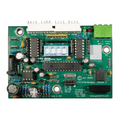
Evolution Controls 1 Series User manual

©Evolution Controls Inc.
22-Nov-2019
Evolution
Automation Interface ..CONTROLS INC. .EVO™/ECM-ACU+
San Diego, CA USA http://www.gotoevo.com/ Voice (858)748-7359
Made in USA Fax (858) 679-3365
EC Motor Series 1
Application
The EVO/ECM-ACU+ allows industry standard 0V to
+10V automation signals to adjust and monitor EC
Motors. These are fractional horsepower air moving
motors featuring an internal microprocessor based
drive. The design provides exceptional efficiency,
performance and motor life. The motor may be
factory configured to provide constant mass airflow
or constant torque over the configured control range.
The ACU+ provides remote adjustment of the motor
output from 0 to 100% of the motor’s programmed
control range. A signal lamp on the control
continuously flashes out the flow index
1
. Instruments
are not required to read the flow index. A 0V - +10V
signal connects RPM to the automation control.
Jumpers allow the ACU+ to be configured for 0V to
+10V automation signal, +2V to +10V automation
signal, and manual/override control. The ACU+ can
also be used for stand-alone manual control.
Signal Lamp
The green lamp continuously indicates the flow
index. After a pause, the lamp flashes out the tens
digit, then the units digit of a number between 1 and
99. Long flashes represent the tens digit, and short
flashes represent the units digit. For example, a
flow index of 23 flashes two longs, then three shorts.
Two extra long flashes indicate a flow index of 0. An
extra long flash and ten short flashes indicates a
flow index of 100. The lamp flashes the signal that
was present when the flash sequence started.
Turning Adjust controls the EC motor to the
manually adjusted setting. The manual setting has
authority for 15 minutes.
Ordering
EVO/ECM-ACU+ Control without metal plate
EVO/ECM-ACU+ -MP Control mounted to a single
gang (US) metal plate.
1
Flow Index = percent of the programmed control range.
Manual Override
•Temporary local Adjust for air balance.
•Manual control without any 0 - +10V signal.
•Local Default
•Startup mode keeps control in Manual until
automation is connected.
When local adjust is turned, Vspd is set by Adjust.
Vspd remains at the Adjust value for 15 minutes
after the last Adjust movement is detected allowing
time to make airflow measurements.
With the “M” jumper in place, Adjust controls the
motor when a +0.1-+10V control is not detected.
This feature allows the ACU+ to be used as a
manual control. And it provides a local default for
critical applications by providing a safe operating
speed should the +0.1-+10V signal fail.
The ACU+ is provided new with startup mode
enabled. The control behaves like the “M” jumper is
in place, even if it is not. This allows the mechanical
equipment to be tested and used before automation
is installed. After automation is installed, the startup
mode can be disabled by starting/stopping the motor
five times with a +0.1-+10V signal present. The
motor start/stop event may be performed by cycling
~24V
2
power to the control with the control signal
above +0.1V, or by raising and lowering the +0.1 -
+10V signal with the “P” jumper installed.
2
~24V = 24Vac
Equipment manufacturer:
Please use the model above
as your part number, or in
your description.

©Evolution Controls Inc.
22-Nov-2019
Series 1 EVO/ECM-ACU+
San Diego, CA USA http://www.gotoEVO.com Page 2of 6
Jumpers
“P” The "P" jumper provides
ON/OFF control by switching
the motor's "GO" control line
off when the signal drops
below +1 (2mA) volt and on
when the signal exceeds
+2V (4mA). Adjust turns the
motor On/Off with the “P”
jumper installed.
Without the jumper, turn ACU+ power
On/Off to control motor On/Off.
“M” The “M” jumper enables manual override. In
manual override, the fan speed is controlled
by the local Adjust when the automation
signal is below +0.2V. It controls the motor
before automation is installed, or when
automation fails. It returns to automation
control when the signal is above +0.2V.
Without the “M” jumper, manual override is
enabled whenever Adjust is turned. It
remains enable for 15 minutes and then
returns to automation control.
“S”The “S” jumper reverses Adjust rotation so
adjustment is correct from the component
side of the board (sometimes marked “R”).
“Opt” The Opt. space has no function. The space
may be used to store an unused jumper.
Specifications
Power NEC Class II or equal
~24V ± 20% 50/60 Hz
2W, 4VA + 1VA/Motor
Control
Signal no "P" jumper
0V to +10V = 0%-100% pwm
"P" Jumper
+2 to +10V = 0%-100% pwm
4-20mA = 0%-100% pwm
ON/OFF Control Between
+1V & +2V (2 & 4 mA)
RPM
Signal 0V to +10V, 5 mA max.
= 0 to 2,000 RPM in 10 RPM steps
Outputs
Go & VSpd +22V ±2V @ 20 mA
2 motor loads
RPM from 1 motor only
Vspd Supports Autoswitch Function
Thermal
Stability>0.01%/oF
Operating 0oF to 130oF (-18oC to 55oC)
Environment 10-80% rh
Connections 1/4 Tabs
Signal
“P” Jumper Out “P” Jumper In
P
S
M

©Evolution Controls Inc.
22-Nov-2019
Series 1 EVO/ECM-ACU+
San Diego, CA USA http://www.gotoEVO.com Page 3of 6
0.265"
ø
0
.
1
8
7
5
"Use#8Flathead Use4mmFlathead
1.133"
1.429" 36.30mm
1.793" 45.54mm
64.01mm 2.520"
28.78mm
6.73mm
2
1
.
3
9
m
m0
.
8
4
2
"
4
4
.
4
5
m
m1
.
7
5
0
"
Mounting
Mount the ACU+ inside a metal control cabinet or
enclosure. Fasten the mounting posts to an earthed
metal surface.
Mount the ACU+ with clearance for the ~24V power
wires, automation wires and control cable connector.
Mount the control so the Signal and Status lamps are
visible. Make Adjust accessible if it is used in your
application.
The control may be surface mounted, or reverse
mounted so the lamps and Adjust are visible through
the enclosure wall.
The ACU+-MP is a reverse mounted control on an
aluminum single gang US electrical plate. The plate may
be mounted in a single gang electrical box cutout often
used to mount a PSC motor speed control. Mount it to
a single gang handy box to provide separation from
high voltage wiring, or to provide RFI shielding.
The plate is drilled to accommodate most single gang
rectangular outlet trim plates. This plate may be
attached to provide a gasketed seal when mounted in a
weatherproof box, where door is needed to hide Adjust,
or where the ACU+ needs to be wall mounted in an
occupied space.
For manual control, use knob EVO/ACC-Knb3.
For surface mount, remove the shaft and place it into
the Adjust on the component side of the board. A silver
or white surface under the LEDs makes them more
visible from the component side of the ACU+.

©Evolution Controls Inc.
22-Nov-2019
Series 1 EVO/ECM-ACU+
San Diego, CA USA http://www.gotoEVO.com Page 4of 6
IIUSA
Wiring
Power the EVO/ECM-ACU+ with a ~24V NEC Class
power limited transformer
3
. Observe all code
requirements and follow all safety practices regarding
low voltage power supplies and circuits to insure a
safe, reliable installation.
Some applications may require an isolated power
supply or alternative earthing scheme. Follow
applicable code requirements and carefully observe all
safety practices concerning earthing and safety
requirements for low voltage circuits.
Earth one lead of the ~24V side of the power
transformer
4
. Connect the earthed lead to the ACU+
Xfmr neutral connection.
Connect the hot lead of the ~24V side of the power
transformer to the ACU+ Xfmr ~24V connection.
~24V Aux and Neutral are convenience connections.
Up to 20 VA loads may be connected to Aux.
With the “P” jumper out, you may interrupt the Xfmr
connection as a means to stop the motor. Most
automation controllers will power the ACU+ directly
from a ~24V on/off output, eliminating the fan relay.
Automation controllers that switch neutral may require
a fan relay.
The signal input is single-ended, so the ACU+ internally
connects neutral and signal common.
Connect the 0V to +10V control signal to the Signal
connection. Connect the control signal common to the
Common connection.
The input presents a 21K ohm load to the signal
source. Include this resistance when calculating a
dropping resistor for 4-20 Ma operation. A 511 ohm
1% resistor
5
provides a 500 ohm dropping resistance.
Connect to the motor using an EVO/ECM-CBL motor
control cable. The control’s motor cable connector is
small so it may be carefully pulled through an empty
3/4” conduit.
Keep high voltage wiring away from the ACU+ circuitry
or wiring. Follow electrical code requirements for
separation of high and low voltage wiring and
components.
3
See NECUSA 725.41
4
NECUSA 250.20.a.
5
www.Mouser.com pn. 271-511-RC

©Evolution Controls Inc.
22-Nov-2019
Series 1 EVO/ECM-ACU+
San Diego, CA USA http://www.gotoEVO.com Page 5of 6
During Construction
The equipment manufacturer may have set Adjust to allow heating equipment to operate during construction. If
not, Adjust can be set on site to provide a flow to safely operate heating.
Automation Air Balance
If Automation is already installed, air balance can be achieved using automation tools. Please notice that a
control signal less than +0.2V may put the ACU+ into manual override. Avoid setting the automation signal to
less than +0.2V. Caution: turning Adjust locks out the automation signal for 15 minutes.Cycle power for
faster lockout removal.
Manual Air Balance
The ACU+ can be manually adjusted before automation is available. The balancer’s manual adjustment has
authority until automation is connected.
Air Balancer:
1. Use Adjust to set the air flow. This adjustment will have authority for at least 15 minutes.
2. Read the flashing green lamp and record the flow index on the air balance report.
Automation Integrator:
1. Set the Signal to 0V to invoke manual override.
2. Record the RPM on the air balance report.
3. Enter the flow index from the air balance report.
4. Observe the RPM is at or near the RPM observed in step 2.
5. Cycle the motor on/off 5 times.
6
This clears the manual override function unless the “M” jumper is in
place.
Factory Setup
6
Signal must be greater than +0.1V for 0V to +10V applications.
Automation
Permanent Manual Override?
Y Install the “M” jumper
N Remove the “M” jumper
On/Off control using the +2V to +10V Signal?
Y Install the “P” jumper
N Remove the “P” jumper
Manual Adjust from the component side?
Y Install the “S” jumper
N Remove the “S” jumper
Manual Adjust
Manual Adjust Only?
Y Install the “M” jumper
N Remove the “M” jumper
On/Off control using the Manual Adjust?
Y Install the “P” jumper
N Remove the “P” jumper
Manual Adjust from the component side?
Y Install the “S” jumper
N Remove the “S” jumper

©Evolution Controls Inc.
22-Nov-2019
Series 1 EVO/ECM-ACU+
San Diego, CA USA http://www.gotoEVO.com Page 6of 6
EVO/ECM-4Spd Controls 1 Motor &
EVO/ECM-ACU+ Automation RPM Monitor
Optional 2nd Control Monitors Motor 2
Cabling Details
2 Motor Control EVO/ECM-MXC2
The EVO/ECM-MXC2 connects one EVO/ECM-ACU+ to control 2 motors. The master control sets the speed of
both motors. A second control may be connected to monitor the 2nd motor rpm.
Parts:
EVO/ECM-CBL-? Control cable for Genteq 2.3 & 5.0 motor
EVO/USM-CBL-? Control cable for US Motor Perfect Speed
EVO/ECM-PIG-? Control cable with unterminated motor end
EVO/ECM-JMP ? Jumper cable for use with EVO/ECM-MXC2
EVO/ACC-KNB-0 Standard ACU+ Adjust shaft
EVO/ACC-KNB-1 Extended ACU+ Adjust shaft
EVO/ACC-KNB-3 Extended ACU+ Adjust shaft with knob
2.54 mm Shunt Standard ACU+ Option header shunt
This manual suits for next models
2
Table of contents
Other Evolution Controls Recording Equipment manuals
