Louroe Electronics AOP-XD User manual

MODEL AOP-XD
AUDIO TRANSCEIVER INTERFACE
MODEL AOP-SP-WS
SPEAKERPHONE
(wall surface mount)
MODEL AOP-SP-WF
SPEAKERPHONE
(wall flush mount)
MODEL AOP-SP-CS
SPEAKERPHONE
(ceiling surface mount)
MODEL AOP-SP-CF
SPEAKERPHONE
(ceiling flush mount)
AOP-XD 1/08
aop-sp-pb
aop-sp-wf/ws/cf/cs
MODEL AOP-SP-PB
SPEAKERPHONE
WITH
CALL BUTTON
(wall mount)
E
LOUROE
LECTRONICS
6955 VALJEAN AVE, VAN NUYS, CA 91406
PH: (818)994-6498 / FAX: (818)994-6458
MODEL AOP-XD
AUDIO TRANSCEIVER INTERFACE
INSTALLATION AND OPERATING INSTRUCTIONS

Model AOP-XD is a bi-directional audio transceiver and is a companion unit to the Louroe AOP-SP Series
Speakerphones. Its function is to interface two-way audio with:
DVR’s
IP Network Cameras
Video Servers
Soundcard/Soundcard Modules
The AOP-XD provides power to the AOP-SP Speakerphone and drives the audio signals (line level) into the audio
input of the above receiving devices. It also receives the return audio signals from the “Audio Out” or “Speaker Out”
of the DVR, etc. and amplifies the output level for broadcasting through the speaker portion of the AOP-SP
Speakerphone. AOP-XD contains adjustable audio level controls for listen and talkback. Located on the back panel
are RCA and 3.5mm audio input and output jacks for accommodating most DVR’s, IP Network Cameras, etc.
AOP-XD is compatible with the following AOP-SP series Speakerphone Models:
AOP-SP-WF (wall flush mount)
AOP-SP-WS (wall surface mount)
AOP-SP-CF (ceiling flush mount)
AOP-SP-CS (ceiling surface mount)
AOP-SP-PB Call Station
An AOP-XD is required with each AOP-SP series speakerphone.
MODEL AOP-XD
AUDIO TRANSCEIVER INTERFACE
LOUROE ELECTRONICS 6955 VALJEAN AVENUE, VAN NUYS, CA 91406 TEL (818) 994-6498 FAX 994-6458
(818)
WIRING REQUIREMENTS
3 Conductor consisting of:
+
2 Conductor shielded, 20 gauge
with 22 gauge drain
+
1 Conductor unshielded, 20 gauge
All in the same jacket
West Penn 358 or equivalent
AOP-XD 1/08
aop-sp-pb
aop-sp-wf/ws/cf/cs
INSTALLATION AND OPERATING INSTRUCTIONS

AOP-XD
DESCRIPTION AND FUNCTION OF PARTS
AUDIO
INPUT
OUTPUT
+24 Vdc,1A
ABC
SP
AUDIO
INPUT
OUTPUT
6
78
910 11
MAX
MIN MAX
TALKBACK
MINMAX
MONITOR
OVERLOAD
POWER
POWER
E
LOUROE
LECTRONICS
AUDIOOVERPHONE TRANSMITTER duplex
AOP-
1
5
2
4
3
Talkback Level Control Adjusts the output level of audio transmitted to the remote
speaker.
Monitor Level Control Adjusts the level of audio at the receiver location.
Overload Indicator Indicates power supply current overload. Lights red and
automatically disconnects power to the circuit,preventing damage
to the power supply. Restores connection when overload is
removed.
Power LED Indicates power to the unit.
Power Switch Turns ON power.
Power Jack Connects to 24 Vdc power supply (included).
Audio-OUT Phone Jack 3.5mm mono jack that connects to the line level “MIC input” or
“Audio-In” of receiving device (DVR, IP Network Camera, etc.)
Audio-IN Phone Jack 3.5mm mono jack that connects to “Audio-Out” of (DVR,
IP Network Camera, etc.)
Remote Speaker/MIC Terminal Block Connects to remote Speaker/MIC unit (Louroe AOP-SP).
Audio-OUT RCA Jack Same function as Audio-OUT Phone Jack [7].
Audio-IN RCA Jack Same function as Audio-IN Phone Jack[8].
1
2
3
4
5
6
7
8
9
10
11
DESCRIPTION AND FUNCTION OF PARTS
FRONT
PANEL
REAR
PANEL
Figure 1. Parts of AOP-XD
LOUROE ELECTRONICS 6955 VALJEAN AVENUE, VAN NUYS, CA 91406 TEL (818) 994-6498 FAX 994-6458
(818)
AOP-XD 1/08
aop-sp-pb
aop-sp-wf/ws/cf/cs
INSTALLATION AND OPERATING INSTRUCTIONS

WIRING CONNECTION
BETWEEN
AOP-XD AUDIO TRANSCEIVER UNIT
AND
AOP-SP SERIES SPEAKERPHONES
(AOP-SP-CF, AOP-SP-CS, AOP-SP-WF, AOP-SP-WS and AOP-SP-PB)
WIRING CONNECTION TO AOP-SP SPEAKERPHONE
1. Using sample cable, connect one end of the cable to the 4-pin terminal block located on PC
Board of the AOP-SP. Sample cable has RED, BLACK, WHITE and BARE wires. Connect as
follows:
+
Connect RED wire to terminal marked “A” of the AOP-SP.
+
Connect BLACK wire to terminal marked “B” of the AOP-SP.
+
Connect DRAIN wire (bare) to terminal marked “C” of the AOP-SP.
+
Connect WHITE wire to terminal marked “SP” of the AOP-SP.
WIRING CONNECTION TO COMPANION AOP-XD TRANSCEIVER INTERFACE
2. Connect the other end of cable to AOP-XD 4-pin terminal block on back panel as follows:
+
Connect RED wire to terminal “A” of the AOP-XD.
+
Connect BLACK wire to terminal marked “B” of the AOP-XD.
+
Connect DRAIN wire (bare) to terminal marked “C” of the AOP-XD.
+
Connect WHITE wire to terminal marked “SP” of the AOP-XD.
Connections between the AOP-XD and AOP-SP should be “A” to “A”; “B” to “B”; “C” to “C” and
“SP” to “SP.
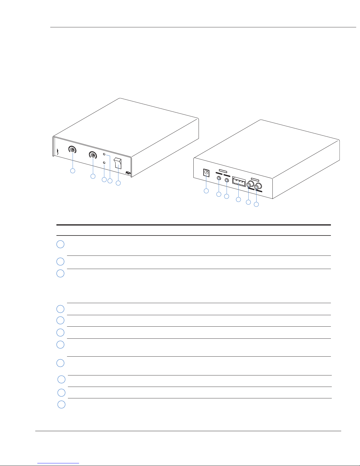
APPLYING POWER TO THE AOP-XD
Included with the AOP-XD is a 24Vdc, 1A power supply. First connect small end of 24Vdc
power supply into the 24Vdc power jack [6] located on back panel of AOP-XD. Then plug
power block into a standard 110V wall outlet or power squid.
CONNECTION FROM AOP-XD TO THE AUDIO RECEIVING DEVICE (DVR, SOUNDCARD, ETC)
The rear panel of AOP-XD contains two types of Audio Inputs and Audio Outputs to accommodate most audio
receiving devices’ inputs and outputs.
RCA type
3.5mm (mini jack) type
(only one set can be used)
Connector cables for both types are included with the AOP-XD, along with a stereo to mono adapter for the
3.5mm cable.
Using either type, connect as follows:
1) Audio Out of AOP-XD to Audio In (or line in) of audio receiving device (DVR, IP Network Camera, etc.)
2) Audio Out of Audio receiving device to Audio In of AOP-XD. Some audio devices such as soundcards
have both a “Mic In” port and a “Line In” port. Use “Line In” or “Audio In”.
NOTE: Do not use Mic In or Mic port on a soundcard. This generally indicates mic level (-55dB/-60dB),
which will be overdriven by the output of the AOP-XD, which is line level (0dB@60W).
LOUROE ELECTRONICS 6955 VALJEAN AVENUE, VAN NUYS, CA 91406 TEL (818) 994-6498 FAX 994-6458
(818)
AOP-XD 1/08
aop-sp-pb
aop-sp-wf/ws/cf/cs
INSTALLATION AND OPERATING INSTRUCTIONS

AUDIO
INPUT
OUTPUT
+24Vdc, 1A
ABC
SP
AUDIO
INPUT
OUTPUT
24Vdc
AC ADAPTER
24Vdc, 1.5A
Audio
Out Audio
In
From Audio Out of
receiving device (DVR, Etc.)
To Audio Input of
receiving device (DVR, Etc.)
ABCSP
INTERCONNECTION DIAGRAM
BETWEEN
LOUROE MODEL AOP-XD AND AOP-SP SERIES SPEAKERPHONES
AOP-SP-WF (wall flush mount)
AOP-SP-WS (wall surface mount)
AOP-SP-CF (ceiling flush mount)
AOP-SP-CS (ceiling surface mount)
AOP-SP-WF/AOP-SP-WS shown
Terminal Block Identifier for AOP-SP and AOP-XD
A - 12Vdc power to mic (red)
B - Audio Output (black)
C - Ground (bare)
SP - Speaker (white)
FIG. 4 Interconnection diagram
MODEL AOP-XD
AUDIO INTERFACE
(rear panel)
PC board of
Model AOP-SP Series
SpeakerPhone
Potentiometers
for
Microphone
Sensitivity and
Speaker Volume
RCA Plug
AUDIOPATH
AUDIOPATH
LOUROE ELECTRONICS 6955 VALJEAN AVENUE, VAN NUYS, CA 91406 TEL (818) 994-6498 FAX 994-6458
(818)
PC Board
WIRING REQUIREMENTS
3 Conductor consisting of:
+
2 Conductor shielded, 20 gauge
with 22 gauge drain
+
1 Conductor unshielded, 20 gauge
All in the same jacket
West Penn 358 or equivalent
AOP-XD 1/08
aop-sp-pb
aop-sp-wf/ws/cf/cs
INSTALLATION AND OPERATING INSTRUCTIONS

SPECIFICATIONS (Mechanical)
Face Plate dimensions for AOP-SP-WF / AOP-SP-PB-F
(flush mount)
Face Plate dimensions for AOP-SP-WS/AOP-SP-PB-S
(surface mount)
Back Box, both models above (included)
6½”W x 8½”L Stainless steel
6”W x 8”L Stainless steel
6”W x 8”L x 4”D
SPECIFICATIONS (Microphone)
SPECIFICATIONS (Speaker)
Microphone output
Current drain
line level (0 dB @ 600Ω)
4 mA
Speaker output
Speaker impedance
Power supply
Weight, net, AOP-SP-WF / AOP-SP-WS
AOP-SP-CF - includes mounting ring
AOP-SP-CS - includes mounting ring
Speaker magnet
Speaker size
5W
8Ω
12 - 15 Vdc
5 Lbs. (2.3 Kg)
3 oz. ceramic
4"
12Vdc
Frequency response
Output Impedance
Supply Voltage
40 Hz to 15kHz ± 1dB
600Ωunbalanced
Type Electret Condenser
AOP-SP-SERIES
SPEAKERPHONES:
AOP-SP-CF
AOP-SP-CS
AOP-SP-WF
AOP-SP-WS
AOP-XD AUDIO TRANSCEIVER
AOP - SP-CF / AOP-SP-CS grill
AOP-SP-CF backbox for flush mount
Inside dimension
Flange
12 ⅞” Dia
9 ¾”
12 ”
Depth 4 ½”
AOP-SP-CS MR-8 Mounting Ring
for surface mount
12 ⅜” X 3”H
LOUROE ELECTRONICS 6955 VALJEAN AVENUE, VAN NUYS, CA 91406 TEL (818) 994-6498 FAX 994-6458
(818)
AOP-XD 1/08
aop-sp-pb
aop-sp-wf/ws/cf/cs
INSTALLATION AND OPERATING INSTRUCTIONS
SPECIFICATIONS AOP-XD
Audio input impedance
Audio output impedance
Frequency response
Power supply requirements
Dimensions
Weight
10K
600
24 Vdc, 1.5A
300 Hz to 3500 Hz
1 ½ lbs. (.68 Kg)
6 ⅛”L x 4 ⅝”W x 1 ”H
16
9
16
5

LOUROE ELECTRONICS 6955 VALJEAN AVENUE, VAN NUYS, CA 91406 TEL (818) 994-6498 FAX 994-6458
(818)
WARRANTY
LOUROE ELECTRONICS warrants that at the time of shipment products manufactured by LOUROE ELECTRONICS to be free of defects in material and workmanship.
Should a defect appear within one year (12 months) from date of shipment, LOUROE ELECTRONICS will, at its sole discretion, repair or replace the defective equipment.
This equipment shall not be accepted for repair or return without prior notification by LOUROE ELECTRONICS.
This warranty does not extend to any Louroe product that has been subjected to improper or incorrect installation, misuse, accident, or in violation of installation
instructions provided by LOUROE ELECTRONICS.
Returned shipments to LOUROE ELECTRONICS shall be at customer’s expense. LOUROE ELECTRONICS will return the equipment prepaid via best way.
IMPORTANT NOTICE
When this equipment is used as part of an
audio monitoring system, the law requires
that the public be given notice of AUDIO
MONITORING ON THE PREMISES. A
decal notice is included with each
microphone shipped.
Federal Law References:
Federal Regulations, US Code, Title 18.
Crime and Criminal Procedure, Sec 2510.
AUDIO
MONITORING
E
LOUROE
LECTRONICS
On
These Premises
AOP-XD 1/08
aop-sp-pb
aop-sp-wf/ws/cf/cs
INSTALLATION AND OPERATING INSTRUCTIONS

E
LOUROE
LECTRONICS
MANUFACTURED
IN THE
LOUROE ELECTRONICS 6955 VALJEAN AVENUE, VAN NUYS, CA 91406 TEL (818) 994-6498 FAX 994-6458
(818)
AOP-XD 1/08
aop-sp-pb
aop-sp-wf/ws/cf/cs
Table of contents
Other Louroe Electronics Recording Equipment manuals