Evoqua WALLACE & TIERNAN S10k User manual

WALLACE & TIERNAN
®
GAS FEEDER
S10k
INSTRUCTION MANUAL

2WT.025.200.000.DE.IM.0517
S10k
Please note
Original manual!

S10k Contents
3
Contents
1. Introduction 7
1.1 Documentation 7
1.1.1 Target groups 7
1.2 Conventions 8
2. Safety 9
2.1 Intended use 9
2.2 General safety instructions 10
2.3 Safety instructions specific to the S10k system 11
3. Description 13
3.1 Design 13
3.2 Principle of operation 14
3.3 Vacuum demand valve 15
3.3.1 Operating knob 17
3.3.2 Heater (optional) 19
3.3.3 Pressure relief valve 19
3.3.4 Flowmeter assembly 19
3.4 Injector 20
3.5 Technical Data 21
4. Installation 23
4.1 Unpacking 23
4.2 Location requirements 23
4.3 Flowmeter assembly 24
4.3.1 Mounting the flowmeter 25
4.4 Installing the vacuum demand valve 25
4.4.1 Connection to a gas cylinder 26
4.4.2 Connection to a chlorine drum 27
4.5 Relief line 28
4.6 Activated carbon filter 28
4.7 Mounting the injector 29

4WT.025.200.000.DE.IM.0517
Contents S10k
4.8 Point-of-application 30
4.9 Water supply 31
4.10 Gas supply line 31
4.10.1 Gas suction line 31
4.11 Commissioning 34
4.11.1 Preparation 34
4.11.2 General check 34
4.11.3 Injector vacuum and leak check 34
4.11.4 Check for gas leaks 35
4.11.5 Check of the vacuum demand valve 36
4.12 Commissioning 37
4.13 Training the operator 37
5. Operation 39
5.1 Starting operation 39
5.2 Shut-down 39
5.2.1 Shut-down for short periods 39
5.2.2 Shutdown for extended periods 40
5.3 Intermittent Start/Stop Operation 40
5.4 Changing Gas Cylinders 41
5.5 Multiple Points - of - Application 42
5.6 Maintenance and inspection plan 43
5.7 Maintenance by the operator 44
5.7.1 Daily check 44
5.7.2 Monthly check 44
5.7.3 Check every three months 44
5.7.4 Further maintenance 45
5.7.5 Changing the activated carbon filter 46
5.7.6 Preparation for Winter Shut-Down 46
5.8 Fault finding 47
6. Maintenance 49
6.1 General 49
6.2 Cleaning the parts 50
6.3 Checking the injector performance 51
6.4 Yearly Maintenance 51

5WT.025.200.000.DE.IM.0517
Contents S10k
6.5 Two-yearly maintenance 52
6.6 Preventive maintenance kits 53
6.7 Necessary tools 54
6.8 Service Notes 55
6.8.1 Servicing the main components 55
6.8.2 Cleaning the flowmeter 55
6.8.3 Cleaning the V-notch plug 56
6.8.4 Cleaning the injector 57
6.8.5 Injector W3T171369 (3/4") 58
6.8.6 Injector W3T171370 (3/4") 59
6.8.7 Injector W3T171367 (1") 60
6.8.8 Antisyphon-injector W3T171368 (1") 61
6.8.9 Cleaning the vacuum demand valve 62
7. Drawings 65
7.1 Typical installations 65
7.1.1 Basic installation for Cl2 or SO2 65
7.1.2 Installation with remote vacuum manifold 66
7.1.3 Installation with switch-over function 67
7.2 Mounting drawings 68
7.2.1 Mounting of flowmeter assembly 68
7.2.2 Mounting of injector 3/4" W3T171369 69
7.2.3 Mounting of antisyphon injector 3/4“ W3T171370 70
7.2.4 Mounting of injector 1“ W3T171367 / W3T171368 71
7.2.5 Injector 3/4" with accessories (N.101.A) 72
7.2.6 Anti-syphon-injector 3/4" with accessory 74
7.2.7 Injector 1" with accessory 76
7.3 Spare parts of the chlorinator 78
7.3.1 S10k Vacuum demand valve 78
7.3.2 Hose connections 83
7.3.3 Flowmeter assembly 5“ (W3T162278 ) 84
7.3.4 Flowmeter assembly 3“ W3T166029 86
7.4 Spare parts for the injectors 88
7.4.1 Injector W3T171367 (1") 88
7.4.2 Anti-syphon injector W3T171368 (1") 90
7.4.3 Injector W3T171369 (3/4") 94
7.4.4 Antisyphon-Injektor W3T171370 (3/4") 96
7.5 Activated carbon filter W3T159902 98
8. Manufacturer declaration 99
9. Index 101

6WT.025.200.000.DE.IM.0517
Contents S10k

S10k Introduction 1.
7
1. Introduction
1.1 Documentation
1.1.1 Target groups
This instruction manual is intended to provide assembly, opera-
ting, and maintenance personnel with the information they need
for running and servicing the S10k remote vacuum gas metering
system.
This instruction manual contains important information which will
enable the operator to run the system in a safe, reliable, trouble-
free, and economical way. Carefully observing these instructions
will help to avoid dangers, reduce repair costs and down times, im-
prove the system's reliability, and prolong its service life.
The entitled „Installation“, „Commissioning“ and „Maintenance by
specialists“ chapters are intended exclusively for Evoqua-authori-
zed technicians or specialists trained and authorized by Evoqua.
These sections contain important information on assembling, con-
figuring, and commissioning the system and on maintenance and
repair work.
All persons working with the system must have read and under-
stood the instruction manual, in particular the safety instructions it
contains.
Please consult the table of contents and the index to quickly find
the information you require.
8WT.025.200.000.DE.IM.0517
Introduction S10k
1.
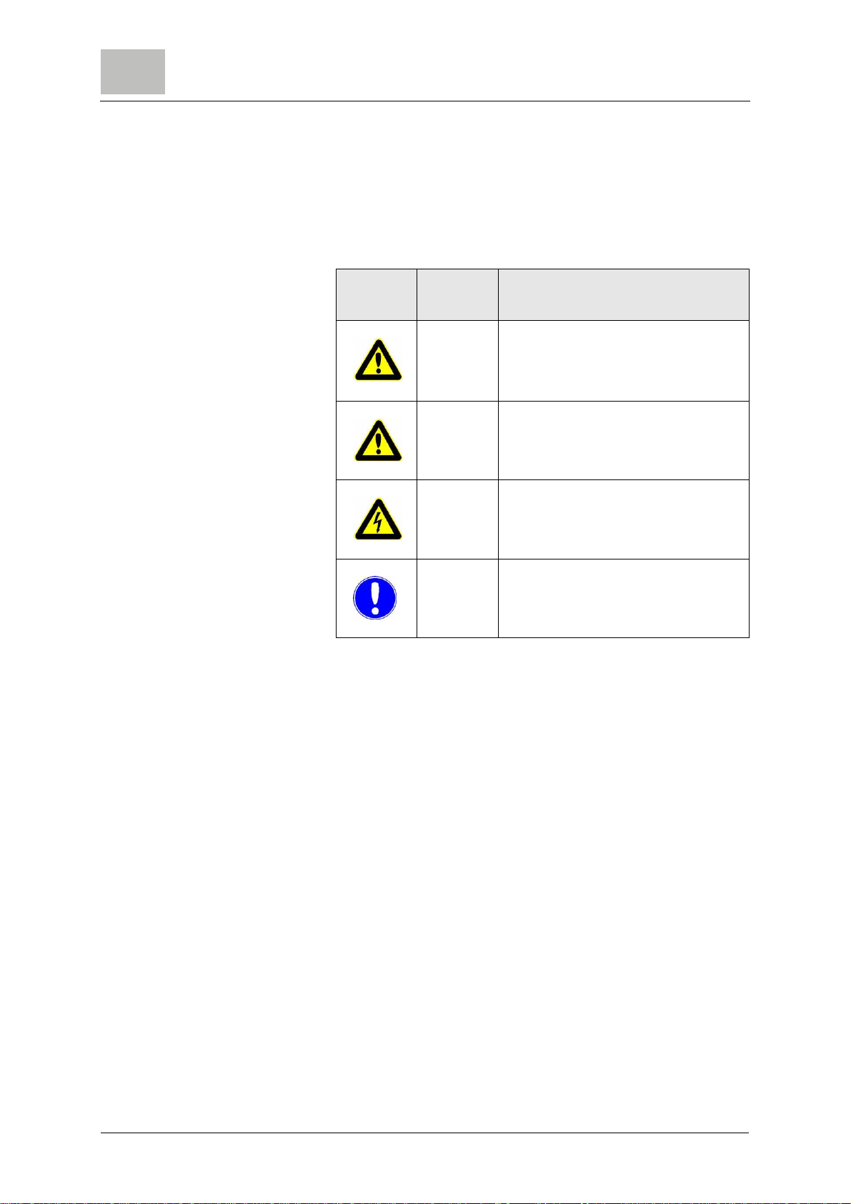
1.2 Conventions
Notes This Instruction manual contains a number of notes with different
priorities marked with symbols.
Picto-
gram Note Meaning
Warning! Danger to life and limb! If the
situation is not handled properly,
death or serious injury may be the
result.
Caution! If this warning is not observed,
medium or slight injury or damage to
the equipment may the result.
Warning! Electrical hazard.
Note These notes assist in the operation
of the system.

S10k Safety 2.
9
2. Safety
2.1 Intended use
The S10k gas feeder is the central item of a disinfection system
which doses chlorine gas, sulphur dioxide or carbon dioxide gas
into a flow of water. Other use is prohibited without permission
from Evoqua.
The vacuum demand valve is designed to fit directly to a chlorine
or sulphure dioxide gas cylinder. For the use with carbon dioxide
the gas pressure must be reduced to 13.5 bar.
Action time is up to 100%.
The operational safety of the system can only be guaranteed if it is
used in accordance with its intended purpose. It may only be used
for the purpose defined in the contract and under the installation,
operating and environmental conditions stated in this operating
manual. No substances (chemicals) may be used other than those
described in this instruction manual. All inspection and
maintenance work must be carried out at the prescribed intervals.
Compliance with the intended use also includes reading this
operating manual and observing all the instructions it contains.
The operator bears full and sole responsibility if this unit is put to
any use which does not comply strictly and exclusively with this
intended use.
Not intended use Not intended use is especially
• use of other media (other gases)
• gas supply under pressure above 13.5 bar.

10 WT.025.200.000.DE.IM 0517
Safety S10k
2.
2.2 General safety instructions
Evoqua attaches great importance to the safety of all work relating
to the system. This was already taken into account in the design of
the system, by the integration of safety features.
Safety instructions The safety instructions in this documentation must always be
observed. These do not affect thevalidity of any additional national
or company safety instructions.
Safety instructions printed on
the system All safety instructions attached to the system must be observed.
They must always be complete and easily legible.
Technical standard The system has been constructed using the best available
technology and according to the accepted safety regulations.
However, danger to the life and limbs of users or third parties or
damage to the system or other property cannot be ruled out if the
system, if the system is used by unqualified persons. Installation
and maintenance, as well as any work that is not described in this
operating manual may only be performed by authorized personnel.
Personnel The operator of the overall system must ensure that only
authorized and qualified technicians can work on or with the
system, and within their specified area of responsibility.
"Authorized and qualified personnel" include:
Operation personnelof theoperator who havebeen trained and instructed by
Evoqua or a service partner.
Installation, Commissioning
and Maintenance level 2 Only Evoqua service personnel or personnel who have been
trained and authorized by Evoqua.
Electrical work Authorized and qualified electrical technicians
Spare parts / components The trouble-free operation of the system can only be guaranteed,
if original spare parts and components are used inthe combination
described in this instruction manual. Otherwise there is a danger
of malfunction or damage to the system.
Modifications and extensions Never attempt to rebuild, modify or extend the system without
written approval from the manufacturer!
Electrical power During normal operation, the control cabinet must remain closed.
Connect cables in accordance with the wiring diagram.
Waste disposal Ensure safe and environmentally-friendly disposal of agents and
replaced parts.

S10k Safety 2.
11
2.3 Safety instructions specific to the S10k system
Warning!
Chlorine gas or sulphur dioxide gas irritates the respiratory tracts.
Contact with chlorine or sulphur dioxide gas in high concentrations
irritates and damages the membranes, respiratory system and the
skin. In extreme cases death can result due to suffocation.
Note
In this manual the use of the S10k system with chorine gas is de-
scribed. When sulphur dioxide or carbon dioxide is used refer to
the safety informations of the gas supplier (e.g. the safety data
sheet).
• This unit may only be installed and serviced by qualified per-
sonnel who are familiar with the contents of the operating
instructions, works directives and regulations for handling
chlorine.
• The operators of the gas feed system must be instructed in
safe use of the unit.
• All personnel coming in contact with the unit must be in full
knowledge of the site operation and emergency procedures
and also regulations for accident prevention.
• The discharge of chlorine gas from chlorine containers should
not exceed one percent of the nominal container contents per
hour, as otherwise there is the risk that the chlorine container
and the vacuum control valve become iced. Therefore ensure
that a sufficient number of chlorine containers are connected
and open at the same time.
• When using chlorine barrels the connection valve must be
heated.
• Always open the chlorine container valve slowly and only by
one turn. This is sufficient for normal operation and in an
emergency the valve can be closed faster. It is also possible
for dirt particles to be pulled off if the value is opened quickly.
These particles then pass through the dirt filter and enter the
valve seat of the vacuum control valve and as a result the
valve no longer closes tightly.
• When changing the gas cylinders always wear a suitable and
functional gas mask. Practice use of the mask regularly. If
chlorine gas is discharged, only use a breathing system which
is independent of ambient air!
• Do not tolerate any leakages in the chlorine system. Leakage
points must be sealed immediately as they will become larger
with time if they remain unattended. When inspecting the sys-
tem for leakage always keep your gas mask to hand.
• All connections and system components must be carefully

12 WT.025.200.000.DE.IM 0517
Safety S10k
2.
inspected for leaks during commissioning, when chlorine pipes
have been released and re-connected and also regularly
during routine daily inspection, and any leaks must be sealed
correctly. If there are any traces of chlorine in the air the cause
must be determined and remedied immediately.
• When locating leaks with ammonia, never pour, spray or drip
liquid ammonia over metal components (corrosion).
• One of the most common causes for leaks on chlorine pipes
are seals which have been used more than once. For this
reason never re-use seals which have been removed from the
system, but dispose of these immediately (also when chan-
ging the gas cylinders!). Ensure that a sufficient supply of new
seals of the right size and correct material is always available
(refer to overhaul kits or spare parts).
• Gaskets must always be stored in a dry place! Damp seals
lose their stability permanently, increase the danger of corro-
sion and should never be re-used!
• If a gas pipe is interrupted or opened, close the openings
immediately with a rubber plug or similar material to prevent
the ingress of moisture. Moisture must be kept away from all
parts of the system which only come in contact with dry chlo-
rine during operation. Dry chlorine is not corrosive below
100°C. However, chlorine in combination with moisture is
extremely corrosive and corrodes most metals such as bronze
or steel.
• Before servicing the system the gas supply must be closed off
directly on the gas cylinders or tank and the chlorine gas in the
system must be consumed completely (exception: leakage
location or calibration).
• Only use original spare parts. Employment of non-specified
parts can cause faults which can have dangerous conse-
quences. Evoqua does not accept any liability in such cases.
• After installation always keep this instruction manual in a safe,
easily accessible place. It is important for safe operation and
correct servicing.
• Secure loose warning signs and replace when illegible.
• Safety inspection once annually by a competent technician.
• Servicing of the system at least once annually by a competent
technician. We recommend concluding a servicing contract
with Evoqua to this purpose.

S10k Description 3.
13
3. Description
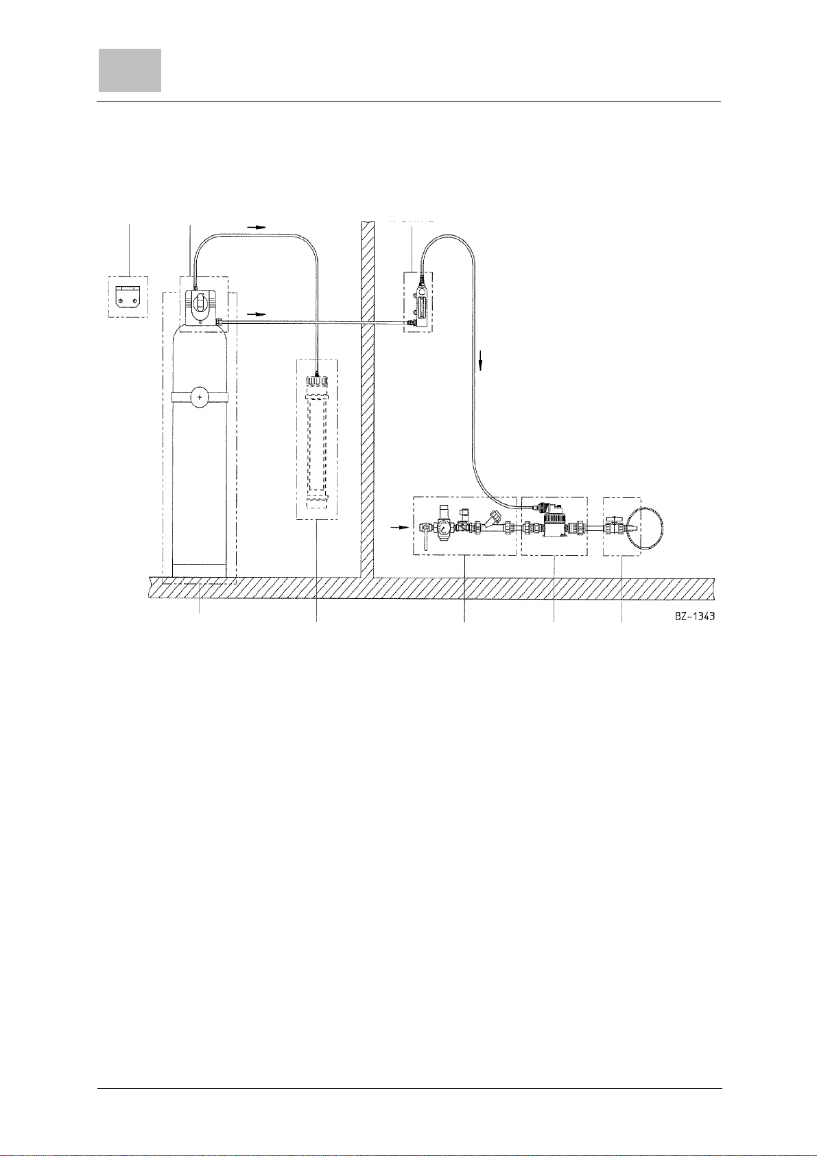
3.1 Design
The system consists of the following main components:
• The separately mounted injector (6) for the generation of the
operating vacuum and for the mixing of the gas with the water.
• The vacuum demand valve (1) is connected directly to the Cl2
or SO2gas cylinder or to the gas manifold. It only opens when
the vacuum created by the injector is sufficient.
For the use with carbon dioxide a pressure reducing valve to
13.5 bar (g) is necessary.
• The gas dosing unit (2) connected to the vacuum demand
valve via the vacuum line.
It includes the flowmeter to display the gas flow and the V-
notch plug to adjust the gas flow.
Dosage can be switched on and off by selenoid valves in the water
supply line or by booster pump.
14 WT.025.200.000.DE.IM 0517
Description S10k
3.
.
1 Vacuum demand valve
2 Gas dosing unit
3 Gas cylinder with bracket
4 Activated carbon filter (recommended for chlorine)
5 Operating water supply
6 Injector
7 Point of application
8 Support
3.2 Principle of operation
Operating water passes through an injector (6) and creates a va-
cuum. This vacuum makes the vacuum demand valve (1) on the
chlorine tank open. Chlorine gas enters the control unit (2) under
theinfluence ofthe vacuum andpasses throughthe flowmeterand
further to the injector. There it mixes with the operating water
which then passes to the solution distribution system.
2
8 1
3 4 5 6 7
S10k Description 3.
15
If the operating water is shut off, the vacuum breakes down and
the vacuum demand valve interrupts the chlorine flow. The check
valve in the injector prevents water from entering the gas line. In
case of a leak in the tubing from the regulating valve to the injector
or in the chlorinator, only air can enter into the system, but no chlo-
rine can escape. If the vacuum demand valve leakes and pressu-
rized chlorine flows into the vacuum lines, a relief valve (6) blows
the chlorine into thevent line andinto an activated carbonfilter (5).
It is highly recommended to have the sensor of a gas monitoring
system installed in the chlorine room.
3.3 Vacuum demand valve
The standard vacuum demand valve is supplied for use with chlo-
rine, sulphur dioxide or carbon dioxide gas.
Warning!
The standard vacuum demand valve must not be used for ammo-
nia. Severe personal injury or damage to plant can occur if a va-
cuum demand valve is used with a gas for which it is not designed.
The vacuum demand valve must be connected in a way that only
gaseous gas can enter the valve, never liquid gas.
The function of the vacuum demand valveis to ensure that gas can
only flow from the storage cylinder into the vacuum line when the
vacuum created by the injector is present throughout the pipework.
The vacuum demand valve is supplied in the following assemblies:
• with screw connection for chlorine gas cylinders according to
DIN 477
• with screw connection for SO2 gas cylinders
• with nipple for CO2pressure hose connection
in the versions
• Shut-off valve (non switch-over), withdrawal from one gas
cylinder or gas manifold.
• Switch-over valve, withdrawal from two gas cylinders or gas
manifolds alternatingly.
Warning!
The vacuum demand valve must not be connected directly to a
drum valve. Liquid gas must be prevented from entering the valve.
Connection to a drum is described in chapter 4.4.2

16 WT.025.200.000.DE.IM 0517
Description S10k
3.
Automatic switchover capability is provided (when ordered) by two
vacuum demand valves fitted with mechanical detents machined
into the operating lever. One valve feeds gas until its cylinder is de-
pleted (down to approximately 1 bar). The resulting rise in vacuum
toahigher thannormallevel provides sufficient forcetounlatchthe
operating lever in the second unit which then takes over the gas
supply function.
The vacuum demand valve consists of:
• Operating lever
• Valve housing
• Relief valve
• Cylinder connection
• Heater (optional)
• Pressure gauge, contact pressure gauge (optional)
The discharge of chlorine gas from chlorine containers should not
exceed one percent ofthe nominalcontainer contents per hour,as
otherwise there is the risk that the chlorine container and the va-
cuum demand valve become iced. Therefore connect each chlori-
ne container to a vacuum demand valve. Alternatively connect
several gas cylinders to a gas manifold and connect a vacuum de-
mand valve to the manifold.

S10k Description 3.
17
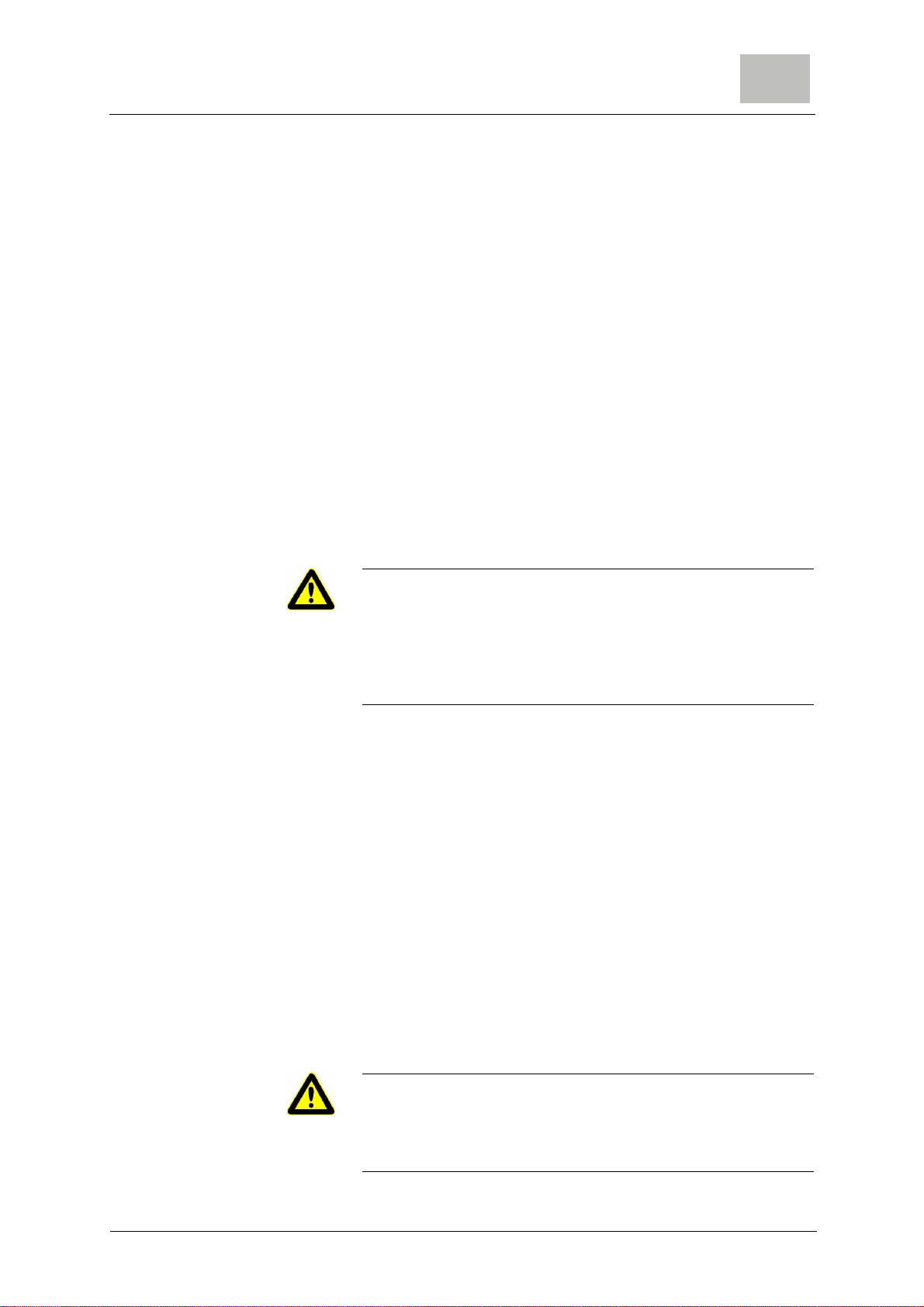
3.3.1 Operating knob
The front cover houses the control mechanism and the front face
is provided with symbols, which indicate the operating condition of
the unit as follows.
Standard version
(non switch-over)
Operation:
closed operating empty
To close the valve:
Move the knob downwards
and turn clockwise.
To open the valve:
Turn the knob anti-clockwise
and move to the top.
18 WT.025.200.000.DE.IM 0517
Description S10k
3.
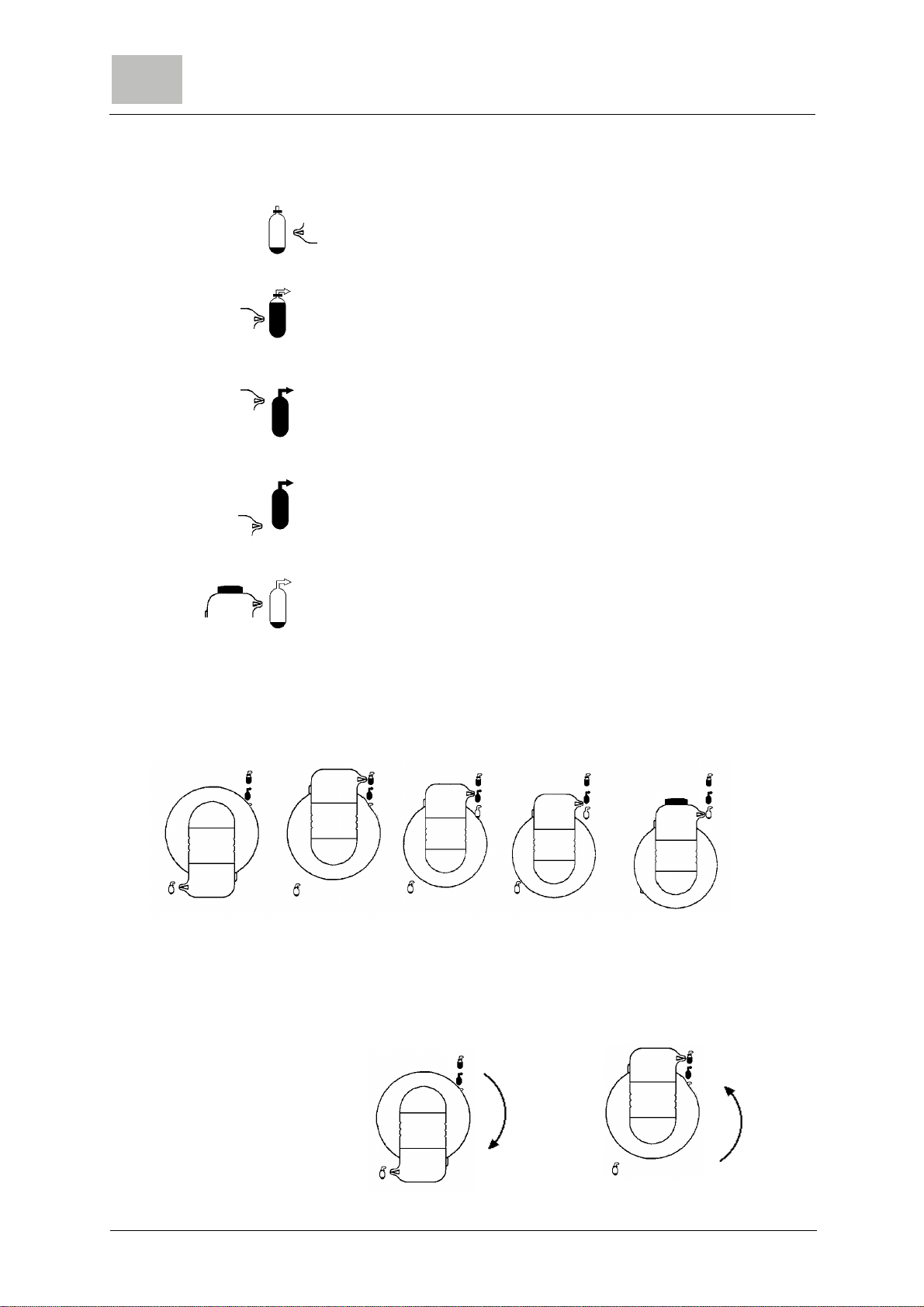
Switch-over version
Closed
standby
(The valve is closed. It opens when the other gas cylinder is empty
and the vacuum rises.
Operating
One cylinder empty or valve closed.
The pressure gauge shows 0 bars.
Both gas cylinders are empty.
The pressure gauge of both gas cylinders show 0 bars.
The red OUT OF GAS warning indicator, located above the knob,
is uncovered.
After the changing of the gas cylinder and the opening of the cylin-
der valve move the knob in position „Standby“ or „Closed“.
Operation:
Closed Standby operating cylinder empty both cylinders empty
To close the valve:
Move the knob downwards and
turn clockwise.
To open the valve:
Turn theknob anti-clockwise and
move to the top.
S10k Description 3.
19
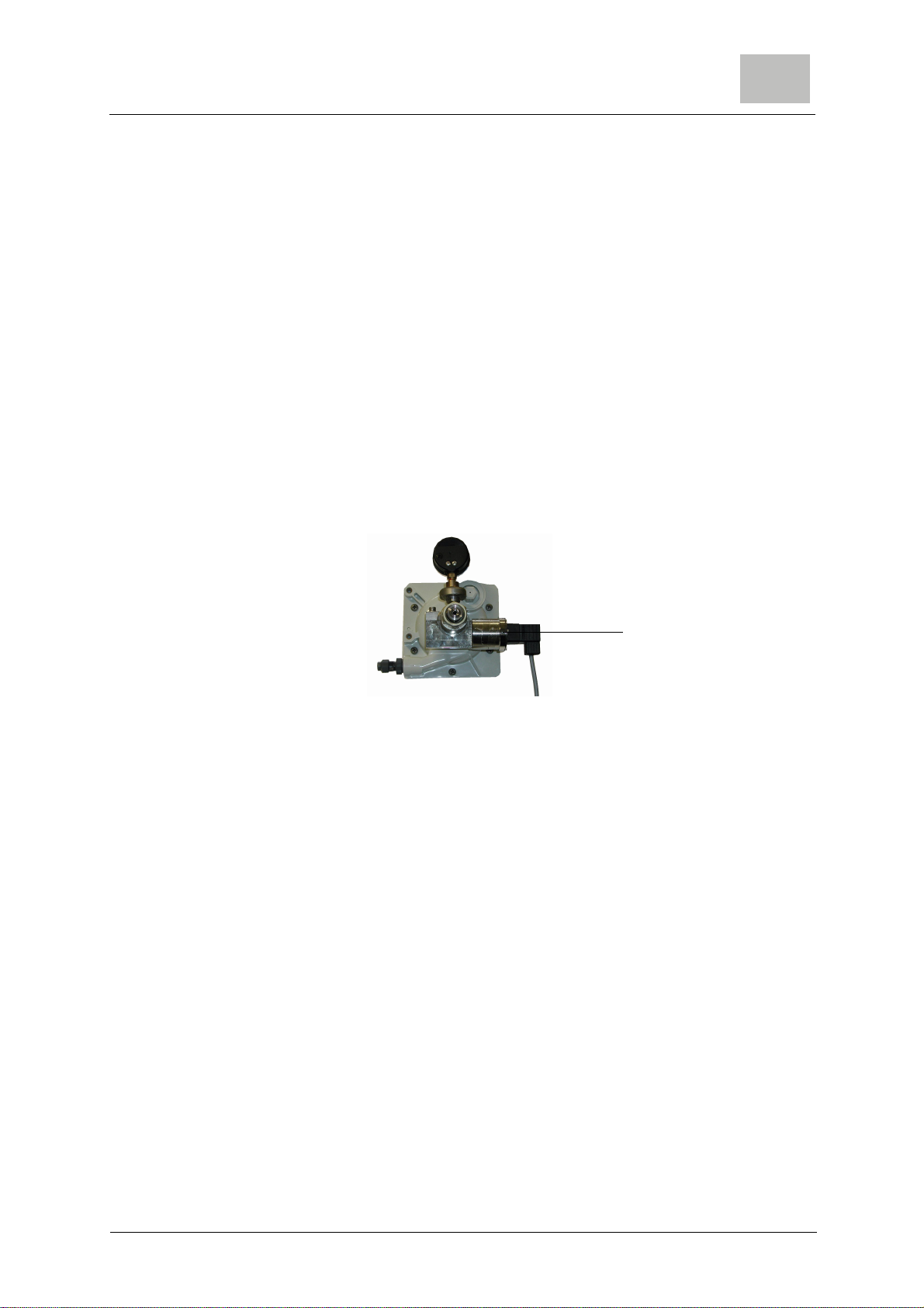
3.3.2 Heater (optional)
An optional heater unit (W3T162239) is available for installations
where reliquefaction of the gas within the valve is a problem due
to low external temperatures. Reliquefaction can occur if the tem-
perature in the vacuum demand valve is below the temperature in
the gas cylinder.
This unit comprises a bolt on capsule which attaches to the check
valve housing of the vacuum demand valve. The thermostatatical-
ly controlled heater is designed to operate on any single phase
supply of 115 volts or over, up to a maximum of 230 volts.
Electric connections must be made by electric specialists accor-
ding to the corresponding rules, e.g. EN 60204.
The LED on the unit is on when the unit is under tension.
The unit can be hot (ca. 60°C).
3.3.3 Pressure relief valve
The pressure relief valve fits into a recess in the back housing of
the regulating valve. The relief valve comprises a spring, stem and
diaphragm. The faceof thediaphragm is springloaded against two
openings, one opening connects into the main chamber of the val-
ve and the other connects to the vent line. Should either of the
check valve stems fail to seat when the operating vacuum is shut
off, gas will pass into the main chamber of the valve where its pres-
sure acts against the underside of relief valve diaphragm. The re-
lief valve diaphragm is forced against its spring until it unseats at
which point gas is allowed to pass to atmosphere via the vent line.
3.3.4 Flowmeter assembly
The flowmeter assembly is fitted with a graduated glass tube and
a control knob. The tubes inner surface is tapered towards the bot-
tom and contains a free moving float. The gas forces the float up
the tube until it can flow round it thus indicating gas flow by the po-
sition of the float in relation to the graduations. The control knob
screws a variable orifice V-notch plug inor outto adjustthe volume
of gas passing through the assembly.
Mounted heater unit

20 WT.025.200.000.DE.IM 0517
Description S10k
3.
Control of the gas feedrate is achieved by by turning the control
knob
• in the anti-clockwise direction to increase the flowrate or
• in the clockwise direction to decrease the flowrate.
If the float touches the upper stop, the range is exceeded and the
reading is not valid.
3.4 Injector
Standard injectors W3T171367 : sizee 1" up to 10 kg/hour
W3T171369: size 3/4" up to 4 kg/hour
The injectors are fitted with check valves to prevent a back flow of
water into the gas feeder if the injector is subject to positive back
pressure when it is shut down or if the solution discharge line be-
comes blocked.
Anti-syphon injectors W3T171368: size 1" up to 10 kg/hour
W3T171370: size 3/4" up to 4 kg/hour
Anti-syphon versions of both injectors are available and are basi-
cally as described above but are fitted with a second, spring loa-
ded, diaphragm assembly to provide a positive shut-off against
negative back pressure at the injector.
Both the standard and anti-syphoninjectors are mounted remotely
from the demand valve and the flowmeter assembly.
Table of contents
Other Evoqua Industrial Equipment manuals


Popular Industrial Equipment manuals by other brands


JCM GLOBAL
JCM GLOBAL UBA Pro RT Series Operation and maintenance manual

Eaton
Eaton RMQ-Titan C22-PV Series Original operating instructions

Kobelt
Kobelt 7166 Electric Helm Owner's Operation, Installation & Maintenance Manual

Hamworthy
Hamworthy EVO S 80 instructions

BVA Hydraulics
BVA Hydraulics HD15002 instruction manual

Crystal Clean
Crystal Clean 2740 operating manual


