Evoqua V10K User manual

1
INSTRUCTION MANUAL
V10K AUTOMATIC
WALLACE & TIERNAN®
VACUUM GAS FEEDER
FOR Cl2 AND SO2

2
V10k automatic
EN
In some countries, DEPOLOX, OSEC, Barrier, Chem-Ad and Wallace & Tiernan are trademarks of Evoqua, its subsidiaries or
affiliated companies. No part of this document may be reproduced in any form (printed, photocopy, microfilm, or any other
procedure) or saved, processed, copied, or distributed using electronic data systems - without the express prior written con-
sent of Evoqua Water Technologies GmbH.
All information in this document is considered reliable and corresponds to the generally applicable technical standards. Evo-
qua assumes no responsibility for the completeness of this information. Users are responsible for making sure that the pro-
duct is suitable for specific applications. Evoqua assumes no liability for specific or indirect damage or consequential
damage arising from the sale, resale or misuse of its products.
NOTICE
Translation of the original instruction.

V10k automatic
3
EN
Contents
1. Introduction 4
1.1 Documentation........................................................................................................4
1.2 Conventions.............................................................................................................4
2. Safety 5
2.1 Intended use ...........................................................................................................5
2.2 General safety instructions .....................................................................................5
2.3 Safety instructions specific to the V10k system ......................................................6
3. Description 8
3.1 Principle of operation..............................................................................................8
3.2 Control possibilities .................................................................................................8
3.3 Design......................................................................................................................9
3.4 Technical Data .......................................................................................................10
4. Installation 11
4.1 Scope of supply .....................................................................................................11
4.2 Transport and storage...........................................................................................11
4.3 Mounting...............................................................................................................12
4.4 Gas supply line.......................................................................................................13
4.5 Electric connection ................................................................................................14
4.6 Insert the flowmeter .............................................................................................16
4.7 Remove and mount the cover...............................................................................17
4.8 Preparation............................................................................................................17
4.9 Commissioning ......................................................................................................18
4.10 Training the operator ............................................................................................19
5. Operation 20
5.1 General ..................................................................................................................20
5.2 Start dosing ...........................................................................................................20
5.3 Stop dosing............................................................................................................20
5.4 Changing gas containers........................................................................................20
5.5 To stop for extended periods or maintenance......................................................20
5.6 Fault finding...........................................................................................................21
5.7 Maintenance and inspection plan ........................................................................24
6. Maintenance 25
6.1 Changing the activated carbon filter.....................................................................25
6.2 Cleaning the parts .................................................................................................26
6.3 Maintenance of the chlorinator ............................................................................26
6.4 Maintenance of the injector..................................................................................27
6.5 Preventive maintenance kits.................................................................................29
6.6 Positioner ..............................................................................................................39
7. Drawings 42
7.1 Typical installations ...............................................................................................42
7.2 Mounting drawings ...............................................................................................44
7.3 V10k chlorinator....................................................................................................53
7.4 Injectors.................................................................................................................59
8. Wiring diagram 67
9. Declaration of conformity 68
10. Notes 70

1. Introduction V10k automatic
4
EN
1. Introduction
1.1 Documentation
1.1.1 Target groups
This instruction manual is intended to provide
assembly, operating, and maintenance per-
sonnel with the information they need for run-
ning and servicing the V10k remote vacuum
gas metering system.
This instruction manual contains important
information which will enable the operator to
run the system in a safe, reliable, trouble-free,
and economical way. Carefully observing
these instructions will help to avoid dangers,
reduce repair costs and down times, improve
the system's reliability, and prolong its service
life.
The chapter „Installation“ and parts of the
chapter „Maintenance“ are intended exclusi-
vely for Evoqua-authorized technicians or spe-
cialists trained and authorized by Evoqua.
These sections contain important information
on assembling, configuring, and commissio-
ning the system and on maintenance and
repair work.
All persons working with the system must
have read and understood the instruction
manual, in particular the safety instructions it
contains.
Please consult the table of contents to quickly
find the information you require.
1.2 Conventions
This Instruction manual contains a number of
notes with different priorities marked with
symbols
.
DANGER
Danger to life and limb! If the situation is not
handled properly, death or serious injury
may be the result.
WARNING
Danger to life and limb! If the situation is not
corrected, death or serious injury can result.
AT TENTION
If this warning is not observed, medium or
slight injury or damage to the equipment
may the result.
WARNING
Electrical hazard.
NOTICE
These notes assist in the operation of the
system.

V10k automatic 2. Safety
5
EN
2. Safety
2.1 Intended use
The V10k chlorinator is the central item of a
disinfection system which doses chlorine gas
or sulphur dioxide gas into a flow of water. For
the use with carbon dioxide a separate instruc-
tion manual is available.
The V10k vacuum gas metering system must
be connected to a vacuum gas supply.
Action time is up to 100%.
Other use is prohibited without permission
from Evoqua.
The operational safety of the system can only
be guaranteed if it is used in accordance with
its intended purpose. It may only be used for
the purpose defined in the contract and under
the installation, operating and environmental
conditions stated in this operating manual. No
substances (chemicals) may be used other
than those described in this instruction
manual. All inspection and maintenance work
must be carried out at the prescribed inter-
vals.
Compliance with the intended use also inclu-
des reading this operating manual and obser-
ving all the instructions it contains.
The operator bears full and sole responsibility
if this unit is put to any use which does not
comply strictly and exclusively with this inten-
ded use.
Not intended use is especially
• use of other media (other gases)
• gas supply under pressure
2.2 General safety instructions
Evoqua Water Technologies GmbH attaches
great importance to the safety of all work rela-
ting to the system. This was already taken into
account in the design of the system, by the
integration of safety features.
The safety instructions in this documentation
must always be observed. These do not affect
the validity of any additional national or com-
pany safety instructions.
All safety instructions attached to the system
must be observed. They must always be com-
plete and easily legible.
The system has been constructed using the
best available technology and according to the
accepted safety regulations. However, danger
to the life and limbs of users or third parties or
damage to the system or other property can-
not be ruled out if the system, if the system is
used by unqualified persons. Installation and
maintenance, as well as any work that is not
described in this operating manual may only
be performed by authorized personnel.
Personnel
The operator of the overall system must
ensure that only authorized and qualified
technicians can work on or with the system,
and within their specified area of responsibi-
lity.
"Authorized and qualified personnel" include:
Operation and Maintenance leve 1
Personnel of the operator who have been trai-
ned and instructed by Evoqua or a service
partner.
Installation, Commissioning and Main‐
tenance level 2
Only Evoqua service personnel or personnel
who have been trained and authorized by Evo-
qua
Electrical work
Authorized and qualified electrical technicians
Spare parts/components
The trouble-free operation of the system can
only be guaranteed, if original spare parts and
components are used in the combination
described in this instruction manual. Other-
wise there is a danger of malfunction or
damage to the system.
Modifications and extensions
Never attempt to rebuild, modify or extend
the system without written approval from the
manufacturer!
Electrical power
Connect cables in accordance with the wiring
diagram. During normal operation, the posi-
tioner must remain closed. Switch off the
plant before starting mounting, inspection,
maintenance or repair, secure against swit-
ching-on.

2. Safety V10k automatic
6
EN
Waste disposal
Ensure safe and environmentally-friendly dis-
posal of agents and replaced parts.
2.3 Safety instructions specific to
the V10k system
• This unit may only be installed and servi-
ced by qualified personnel who are fami-
liar with the contents of the operating
instructions, works directives and regula-
tions for handling chlorine.
• The operators of the gas feed system must
be instructed in safe use of the unit.
• All personnel coming in contact with the
unit must be in full knowledge of the site
operation and emergency procedures and
also regulations for accident prevention.
• The gas control unit V10k must be con-
nected to a vacuum gas supply only, never
connect to a pressurized gas line.
• The discharge of chlorine gas from chlo-
rine containers should not exceed one
percent of the nominal container con-
tents per hour, as otherwise there is the
risk that the chlorine container and the
vacuum control valve become iced. There-
fore ensure that a sufficient number of
chlorine containers are connected and
open at the same time.
• When changing the gas cylinders always
wear a suitable and functional gas mask.
Practice use of the mask regularly. If chlo-
rine gas is discharged, only use a breat-
hing system which is independent of
ambient air!
• Do not tolerate any leakages in the chlo-
rine system. Leakage points must be sea-
led immediately as they will become
larger with time if they remain unatten-
ded. When inspecting the system for lea-
kage always keep your gas mask to hand.
• All connections and system components
must be carefully inspected for leaks
during commissioning, when chlorine
pipes have been released and re-connec-
ted and also regularly during routine daily
inspection, and any leaks must be sealed
correctly. If there are any traces of chlo-
rine in the air the cause must be determi-
ned and remedied immediately.
• When locating leaks with ammonia, never
pour, spray or drip liquid ammonia over
metal components (corrosion).
• One of the most common causes for leaks
on chlorine pipes are seals which have
been used more than once. For this rea-
son never re-use seals which have been
removed from the system, but dispose of
these immediately (also when changing
the gas cylinders!). Ensure that a suffi-
cient supply of new seals of the right size
and correct material is always available
(refer to overhaul kits or spare parts).
• Gaskets must always be stored in a dry
place! Damp seals lose their stability per-
manently, increase the danger of corro-
sion and should never be re-used!
• If a gas pipe is interrupted or opened,
close the openings immediately with a
rubber plug or similar material to prevent
the ingress of moisture. Moisture must be
kept away from all parts of the system
which only come in contact with dry chlo-
rine during operation. Dry chlorine is not
corrosive below 100°C. However, chlorine
in combination with moisture is extremely
corrosive and corrodes most metals such
as bronze or steel.
• Before servicing the system the gas supply
must be closed off directly on the gas
cylinders or tank and the chlorine gas in
the system must be consumed completely
(exception: leakage location or calibrat-
ion)
• Only use original Evoqua spare parts.
Employment of non-specified parts can
cause faults which can have dangerous
consequences. Evoqua does not accept
WARNING
Danger due to chlorine gas/sulphur dioxide!
Chlorine gas or sulphur dioxide gas irritates
the respiratory tracts. Contact with chlorine
or sulphur dioxide gas in high concentrations
irritates and damages the membranes, respi-
ratory system and the skin. In extreme cases
death can result due to suffocation.
NOTICE
In this manual the use of the V10k system
with chorine gas is described. The safety ins-
tructions for chlorine are similar to those for
sulphur dioxide. When sulphur dioxide is
used refer to the safety informations of the
gas supplier (e.g. the safety data sheet).

V10k automatic 2. Safety
7
EN
any liability in such cases.
• After installation always keep this instruc-
tion manual in a safe, easily accessible
place. It is important for safe operation
and correct servicing.
• Secure loose warning signs and replace
when illegible.
• Safety inspection once annually by a com-
petent technician.
• Servicing of the system at least once
annually by a competent technician. We
recommend concluding a servicing con-
tract with Evoqua to this purpose.

3. Description V10k automatic
8
EN
3. Description
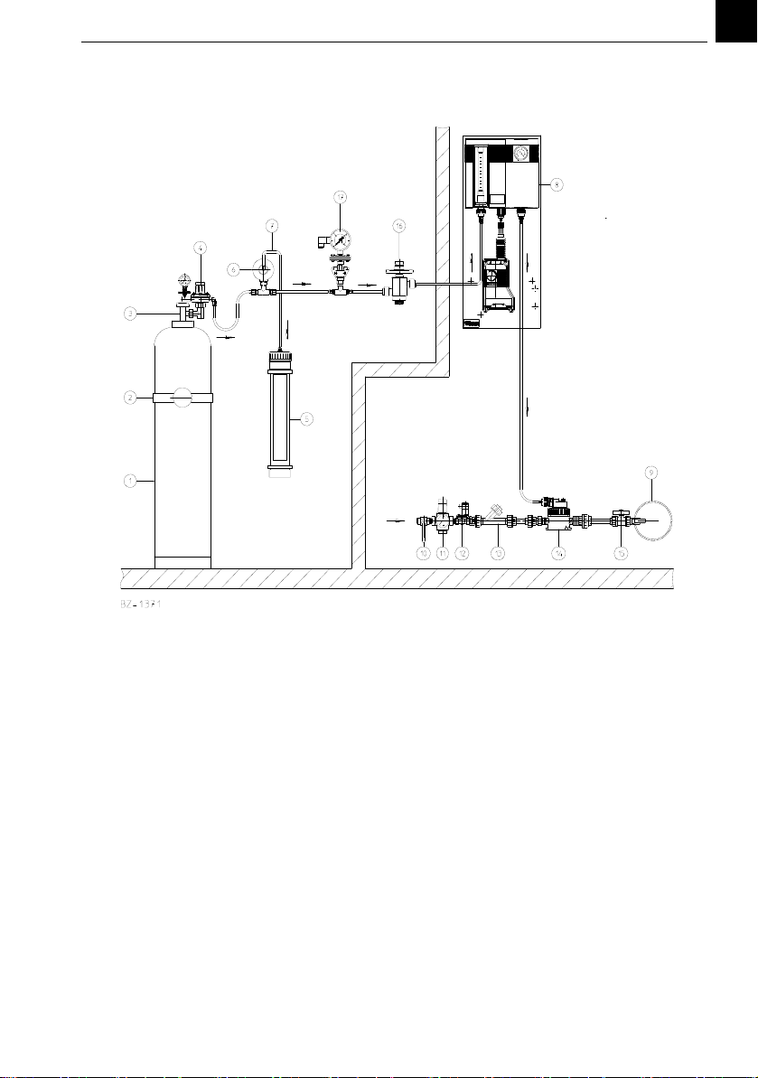
3.1 Principle of operation
Operating water passes through an injector
(14) and creates a vacuum. This vacuum makes
the vacuum control valve (4) on the chlorine
tank (1) open. Chlorine gas enters the control
unit (8) under the influence of the vacuum and
passes through the flowmeter and further to
the injector. There it mixes with the operating
water which then passes to the solution distri-
bution system.
If the operating water is shut off, the vacuum
breakes down and the vacuum control valve
interrupts the chlorine flow. In case of a leak in
the tubing from the vacuum control valve to
the injector or in the chlorinator, only air can
enter into the system, but no chlorine can
escape. If the vacuum control valve leakes and
pressurized chlorine flows into the vacuum
lines, a relief valve (6) blows the chlorine into
the vent line and into an activated carbon filter
(5).
It is highly recommended to have the sensor of
a gas monitoring system installed in the chlo-
rine room.
3.2 Control possibilities
The gas flow is directly indicated on the flow
meter in g/h or kg/h. Within the dosing range,
limited by the v-notch, every dosage rate can
be adjusted (max. 15 kg/h).
automatic:
Dosage rate is adjusted by the positioner. The
positioner is controlled depending on water
flow and/or chlorine residue.
semi‐automatic:
• Dosage rate is adjusted manually. The
injector is switched on and off by sole-
noid valves in the water supply line or by
booster pump.
• Dosage rate is adjusted by the positioner
switched up and down via an external
controller. The injector is switched on and
off by solenoid valves in the water supply
line or by booster pump.
manual:
Pull out the knob on the positioner and turn to
adjust the dosing rate (e.g. in case of failure on
the automatic control). To turn back to auto-
matic control push back the knob and slightly
turn it until it snaps in.
V10k automatic 3. Description
9
EN
3.3 Design
Example for basic chlorinator installation
1 Chlorine gas cylinder
2Mountingbracket
3Cylindervalve
4Vacuumcontrolvalve
5 Activated carbon filter
6 Pressure relief valve
7 Pressure relief tube
8 Chlorinator V10k
9 Point of application
10-13 Operating water supply
14 Injector
15 Stop valve and injection tube
16 Safety valve (optional)
17 Contact pressure gauge (optional)

3. Description V10k automatic
10
EN
3.4 Technical Data
Chlorinator with positioner on mounting plate
The chlorinator can be equipped with different flowmeter tubes and V-notches. By changing
these parts and if necessary the injector, the dosing range can be changed.
with short flowmeter (5") or long flowmeter (10") part no. W3T159301
Regulating range of the V notch *) refer to the shipping documents
Display range of the flowmeter *) refer to the shipping documents
Flowmeter Accuracy class 4
Operating temperature 0°C to +50°C
Operating vacuum approx. 200 mbar
Operating pressure of the 1“ injectors max. 21 bar g up to 20°C,
max. 16 bar g up to 30°C,
max. 12 bar g up to 40°C,
max. 8 bar g up to 50°C
Operating pressure of the ¾“ injectors max. 16 bar g up to 20°C,
max. 13 bar g up to 30°C,
max. 10 bar g up to 40°C,
max. 5,9 bar g up to 50°C
Noise < 70 dB (A)
Positioner 230 V, 50 Hz 19 mA,
positioning time approx. 80 sec.
potentiometer 1 kOhm ± 10%
Positioner 115 V, 60 Hz 46 mA,
positioning time approx. 66 sec.
potentiometer 1 kOhm ± 10%
Dimensions incl. mounting plate (W x H x D)
V10k with positioner 369 x 880 x 185, weight approx. 15 kg

V10k automatic 4. Installation
11
EN
4. Installation
4.1 Scope of supply
The scope of supply includes according to the
selected version:
• Chlorinator with positioner
•Injector
• Operating water supply
• Point of injection
also necessary
•Gassupplywith
• Vacuum control valve
• Release valve with release line and
activated carbon filter
•Vacuumsafetyvalve
(refer to separate instruction manual „Gas
supply“)
4.2 Transport and storage
The chlorinator is shipped in a cardboard box.
1 Check that the box is not damaged.
2 Immediately report any damage to the
freight forwarder.
If the chlorinator is damaged, immedia-
tely inform Evoqua.
3 Check all items against the packing note.
4.2.1 Unpacking
1 Unpack the equipment in a clean, dry
area, preferably at the installation site.
2 Open the packing only on the upper side.
3 Take the accessories out of the cardboard
pocket above the chlorinator.
4 Hold the chlorinator at the mounting
plate or at the positioner, but not at the
red regulator shaft or the positioner rack
and lift out of the packing.
5 To prevent damage during transport the
flowmeter glas is packed separately.
Handle this glas tube very carefully.
Cracks make the glas tube useless.
Preferably mount the flowmeter just
before commissioning.
6 Check all items against the packing note
to ensure that none is discarted with the
packing materials.
7 Retain the packing until the system has
been completely installed.
4.2.2 Location requirements
For drawings of typical installations refer to
7.1
• Unauthorized persons must be excluded
from the installation.
• Adequate access should be available to
permit ease of operation and mainte-
nance of all plant items.
• The gas control unit should be mounted at
eye's height.
• The ambient temperature around the gas
control unit should be at least 0°C (install
a heater if necessary) with a maximum at
50°C (preferably 15 - 20°C).
• The system shall be protected against
direct exposure to sun and moisture.
• Gas containers are heavy and the location
should be choosen to give the shortest
possible gas supply line, consistent with
safe handling of the containers.
• Position and equipment of the chlorine
storage and operation room must corre-
spond to the resp. regulations.
WARNING
Danger due to chlorine gas (gas escape)!
To avoid the risk of injuries due to chlorine
gas, the system must be installed in such a
way that gas is only able to escape into the
room where the gas tanks are stored or into
a separate plant room in the event of a gas
leak. All parts of the system that are liable to
be pressurized (e.g. chlorine tanks, vacuum
control valves, safety pressure relief valves
with activated carbon filters) must therefore
be installed in these rooms. The parts of the
system that are under vacuum may be
installed in another room that is not subject
to specific regulations.

4. Installation V10k automatic
12
EN
4.3 Mounting
(See mounting drawing chapter 7.2.)
4.3.1 Gas Control Unit
1 Mount the gas control unit to a vertical
surface, wall, etc. with the dowels and
screws supplied loose. The flowmeter
should be at a height suitable for reading.
Make shure that the mounting plate is
exactly level and not distorted when tigh-
tening the nuts. The mounting plate
should not touch the wall.
4.3.2 Injector
When installed with rigid pipes the injectors
need not to be fixed elsewhere. When connec-
ted to flexible tubes the injectors have to be
fixed as shown in chapter 7.2.
Nozzle (with stamped number) and tailway
(with stamped letter) are supplied loose.
1 Place the o-rings on both and apply some
vacuum grease (do not use mineral
grease).
2 When assembling nozzle and tailway into
the injector body pay attention to the
flow direction (see arrows on the injector
body). Turn only by hand up to the stop.
For measuring the injector vacuum a 1/4" con-
nection is provided.
Operation range:
Up to 4 kg/h:
standard injector W3T171369 (3/4") or anti-
syphon injector W3T171370
Above 4 kg/h:
standard injector W3T171367 (1") or anti-
syphon injector W3T171368
The anti-syphon injectors are necessary, when
depression can occur in the water pipe, e.g. by
water flowing downwards.
Injector W3T171369/W3T171370
Connection at the throat:
3/4“ hose or threaded tube
If connected to 3/4" rigid tube, the part of the
nozzle that is prepared for accepting flexible
tube can be removed. Carefully deburr and
remove the residues.
The gas connection can be turned in 45° steps
after loosening the union nut. Lock before
tightening the union nut. Tighten only by
hand!
Injector W3T171367/W3T171368
Connection at the throat:
PVC tube DN 25 (Ø32 mm)
Connection at the tailway:
PVC tube with 3/4“ inner thread
The gas connection can be turned in 60° steps.
To do so remove the 6 bolts, remove the upper
part of the housing and fix again in the desired
position. Tighten the bolts equally.
4.3.3 Point‐of‐application
If the point-of-application is a pressurized
main or is higher than the injector, the solu-
tion line should incorporate a check valve and
terminate in a solution injection tube assem-
bly.
WARNING
Danger due to chlorine gas (gas escape)!
To avoid the risk of injuries due to chlorine
gas, the system must be installed in such a
way that gas is only able to escape into the
room where the gas tanks are stored or into
a separate plant room in the event of a gas
leak. All parts of the system that are liable to
be pressurized (e.g. chlorine tanks, vacuum
control valves, safety pressure relief valves
with activated carbon filters) must therefore
be installed in these rooms. The parts of the
system that are under vacuum may be
installed in another room that is not subject
to specific regulations.
WARNING
To avoid possible severe personal injury or
damage to the plant this equipment should
be installed, operated and serviced only by
trained qualified personnel. Do not modify
the installation beyond what is described in
this manual without explicit consent of Evo-
qua.
AT TENTION
Never shorten the tailway. The tube connec-
ted to the tailway must be straight for at
least 0,30 m more. Otherways the flow in
the pressure-recovery zone will be interrup-
ted and prevent normal performance.
V10k automatic 4. Installation
13
EN
The injection tube consists of a pvc stop valve
and a tube with threaded connection, that
extends to approx. 1/3 of the mains diameter
when extended.
It is recommended that all solution delivery
lines be fitted with a suitable valve and drain
pipe to enable any pressure build up to be
safely released prior to maintenance work.
4.3.4 Water supply
To operate the injector, a water supply pipe of
at least 3/4“ diameter is necessary according
to the operating conditions.
There must always be sufficient operating
water available at an adequate supply pres-
sure (see Technical Data for details). The ope-
rating water must not contain any particulates
(potable water quality).
Water pressure and quantity depend on the
maximum dosing capacity, the counterpres-
sure at the point of application, the difference
in geodetic altitude between chlorinator and
point of application and the friction in the
dosage line. On these values depend the selec-
tion of the injector.
If the operating water pressure is too low, a
booster pump is required.
The water line should include a suitable shut-
off valve, strainer, pressure gauge, pressure
reducing valve check-valve and solenoid valve
(see chapter 7.1).
It is recommended that all solution delivery
lines lines be fitted with a suitable valve and
drain pipe to enable any pressure build up to
be safely released prior to maintenance work.
4.4 Gas supply line
For reducing the pressure from the chlorine
tanks, a vacuum control valve and a safety
relief valve are necessary (see also typical ins-
tallation).
For the vacuum control valves a separate inst-
ruction manual „Gas supply“ is available.
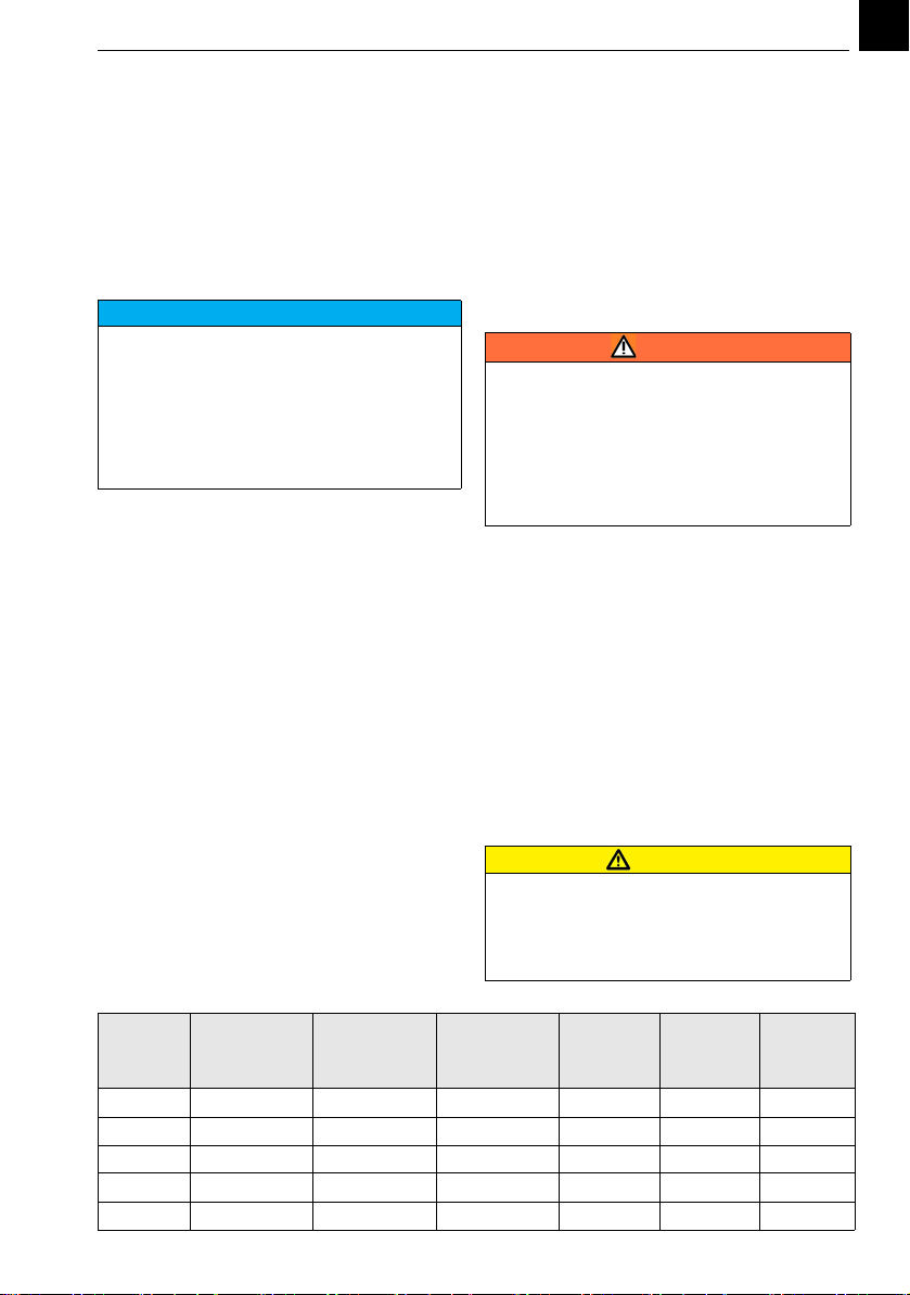
4.4.1 Gas suction line
The diameter of the suction line between
vacuum control valve, control unit and injector
depends on the the gas flow and the distance
(see table below).
Max. tube/pipe length from vacuum control valve to the V10k
NOTICE
Behind the point-of-application a pipe
length of at least 10...15 x pipe diameter is
necessary for a homogenious mixing of the
solution into the main water. After that,
samples can be taken for residue control
etc. If the point-of-application is into a basin,
channel etc. a diffusor can be supplied (refer
to the project documentation.
WARNING
Danger due to chlorine gas !
The gas control unit must be connected to a
vacuum gas supply only.
Do not open the cylinder or drum valve until
the system has been fully installed and the
pre-start checks are being carried out.
Refer to the safety information of the gas
supplier and the safety data sheet!
ATTENTION
When using polyethylene pipes don't install
them in narrow, badly vented protection
pipes or in the ground to prevent the pipe
from fast embrittling under the influence of
chlorine.
Feed of
Cl2, SO2
in g/h
PE hose
6,35 mm
(1/4“)
PE hose
9,5 mm
(3/8“)
PE hose
12 mm
(1/2“)
PVC pipe
DN 15
PVC pipe
DN 20
PVC pipe
DN 25
200 250 m 1200 m 3000 m - - -
400 146 m 670 m 1510 m 3600 m - -
1000 24 m 88 m 852 m 1710 m - -
2000 6 m 33 m 107 m 320 m 1094 m -
3000 3 m 16 m 53 m 179 m 607 m 1853 m
4. Installation V10k automatic
14
EN
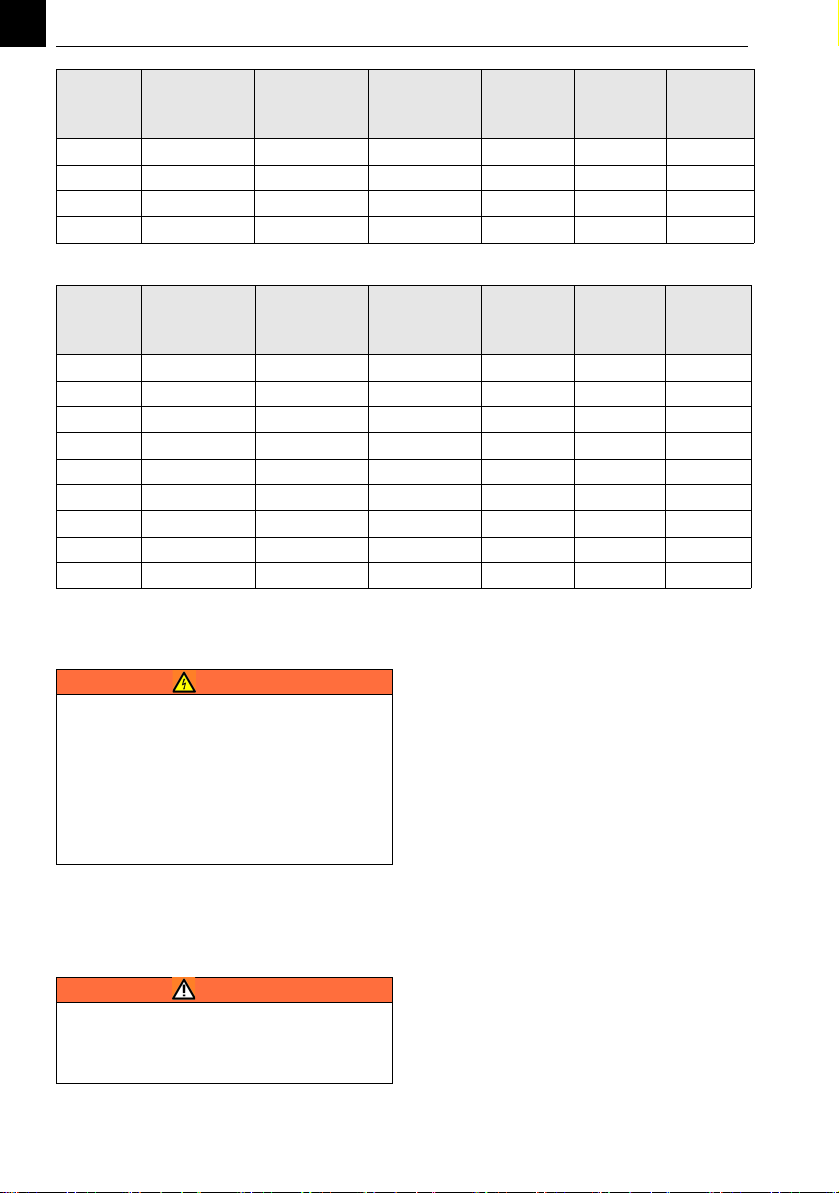
Max. tube/pipe length from V10k to injector
4.5 Electric connection
4.5.1 Connecting solenoid valve / boo‐
ster pump
refer to Typical Installations in chapter 7.1
A booster pump is necessary if the operation
water pressure is too low.
1 Lock the booster pump to the flow in the
main water line (e.g. by using a flow sen-
sor)
When using a solenoid valve in the main water
line:
1 Lock the solenoid valve to the flow in the
main water line (e.g. by using a flow sen-
sor)
4.5.2 Connecting the positioner
The positioner can be connected to a Evoqua
control unit, other controls or a remote cont-
rol panel.
Connect the positioner according to wiring
diagram 30-E-7693 (see chapter 8 and the ins-
tructions of the control).
• CLOSE/DEC: connecting rod moves out,
chlorinator flow decreases,
• OPEN/INC: connecting rod moves in, chlo-
rinator flow increases.
The positioner is supplied with three cable
glands and two plug screws. Insert as applica-
ble. The following bores are provided:
• for 230 V positioners: ø 20.5 mm
4000 - 9 m 28 m 91 m 364 m 1042 m
6000 - 5 m 15 m 43 m 145 m 479 m
8000 - 2 m 8 m 25 m 98 m 294 m
10000 - 1, 5 m 5 m 16 m 73 m 206 m
Feed of
Cl2, SO2
in g/h
PE hose
6,35 mm
(1/4“)
PE hose
9,5 mm
(3/8“)
PE hose
12 mm
(1/2“)
PVC pipe
DN 15
PVC pipe
DN 20
PVC pipe
DN 25
Feed of
Cl2, SO2
in g/h
PE hose 6,35
mm (1/4“)
PE hose 9,5
mm (3/8“)
PE hose 12
mm (1/2“)
PVC pipe
DN15
PVC pipe
DN20
PVC pipe
DN25
200 415 m 2000 m - - - -
400 243 m 1115 m 2515 m - - -
1000 40 m 146 m 1420 m 2850 m - -
2000 10 m 55 m 178 m 532 m 1748 m -
3000 5 m 26 m 88 m 298 m 1010 m 3088 m
4000 - 15 m 46 m 151 m 606 m 1736 m
6000 - 7 m 25 m 71 m 240 m 798 m
8000 - 4 m 13 m 40 m 163 m 490 m
10000 - 2, 5 m 8 m 26 m 121 m 343 m
WARNING
To avoid personal injury by electrical energy
only authorized and qualified electrical per-
sonnel may carry out works on electrical
parts of the system.
Connect the control cabinet according to the
wiring diagrams and the national and local
codes. Before opening positioner or electric
control unit, ensure that mains supply is
switched off.
WARNING
Danger of over-chlorination!
The water through the injector may flow
only when the water in the main water line
flows.

V10k automatic 4. Installation
15
EN
• for 115 V positioners: ø 22 mm
1 To open the cover:
Remove the knob (Allen key 2 mm),
2 Unscrew the upper part of the housing.
Lift the lateral brackets and pull the cover
away.
3 Connect the positioner.
Make sure that the gear case of the posi-
tioner is safely connected to protection
ground.
4 In order to separate the positioner from
the mains during service or repair, install a
2 pole switch between the control unit
and the positioner not far from the posi-
tioner.
5 Check the function.
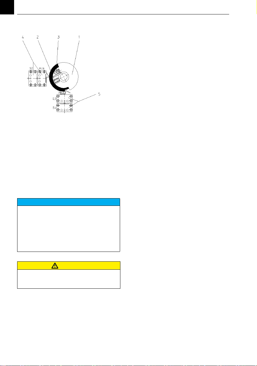
4.5.3 Adjusting the positioner
The positioner is supplied pre-adjusted to the
chlorinator. Adjusting can become necessary
e.g. if the system should be adjusted to a diffe-
rent '0'-position or after repair.
The lower limit can be shifted upwards up to
60% of the range (e.g. for basic chlorination).
Preparation
1 Switch off the mains to the positioner and
to the limit switches and ensure that the
wires are free of voltage.
2 Disengage the motor by pulling the knob
out.
3 Remove the knob (set screw, Allan key 2
mm)
4 Unscrew the cover, lift the side clips and
remove the cover.
5 Replace the knob or turn the knob shaft
with a screw driver.
Adjust the MIN limit
1 Move the connecting rod fully outside
and then 2 mm back.
2 Loosen the set screw (pos. 2) of the cam
disk (pos. 1).
The corresponding key is fixed in the
cover.
3 Turn the cam disk until both MIN-limit
switches (pos. 4) are switched by the
upper part of the cam disk.
4 Press the cam disk to the stop and fasten
the setscrew without turning the cam
disk.
Adjust the MAX limit
1 Move the connecting rod fully inside and
then 2 mm back.
2 Turn the lower part of the cam disk by
turning the set screw (Pos. 3) so far that
both MAX switches (Pos. 5) are switching.
Don't loosen or turn the whole cam disk.
3 Check by moving the connecting rod.
4. Installation V10k automatic
16
EN
Adjust the reduced MAX limit
1 Set the connecting rod to the desired
max. end switching point, i.e. to the desi-
red, reduced max. dosing rate.
2 Turn the lower part of the cam disk (Pos.
2) by turning the set screw (Pos. 3) until
both MAX switches (Pos. 5) engage audi-
bly. Do not release or turn the cam disk as
a whole as you do this.
3 Then check both end switching points, the
zero setting and reduced max. end swit-
ching point again by displacing the con-
necting rod in Manual mode.
Adjust the feedback potentiometer
Adjustment is necessary, when a new board is
mounted in the positioner or the motor-gear-
unit has been removed or changed.
1 Open the cover (see preparation)
2 Pull off connectors 13/14/15
3 Move the connecting rod fully outside to
the stop.
4 Connect an ohmmeter to the terminals 13
and 14 on the board.
5 Loosen the great output tooth wheel on
the shaft below the cam wheel.
6 Turn the tooth wheel until the ohmmeter
displays between 10 and 30 ohm.
7 Fix the tooth wheel without turning it.
8 Move the connecting rod fully inside to
the stop.
9 Ohmmeter must display resistance smal-
ler than the total resistance of 1kohm
measured between the terminals 13 and
15.
10 Check both adjustments by moving the
connecting rod.
11 Remove the ohmmeter and connect the
terminals 13/14/15 again.
Close the cover
1 Remove the knob, if mounted.
2 Place the cover without damaging the
shaft sealing.
3 Move the connecting rod fully outside.
4 Place the knob on the shaft, turn that the
arrow points to the minimum and fix.
5 Switch to automatic operation (press in
the knob), if necessary turn slightly to let
the tooth wheels match.
6 Switch on and check for function.
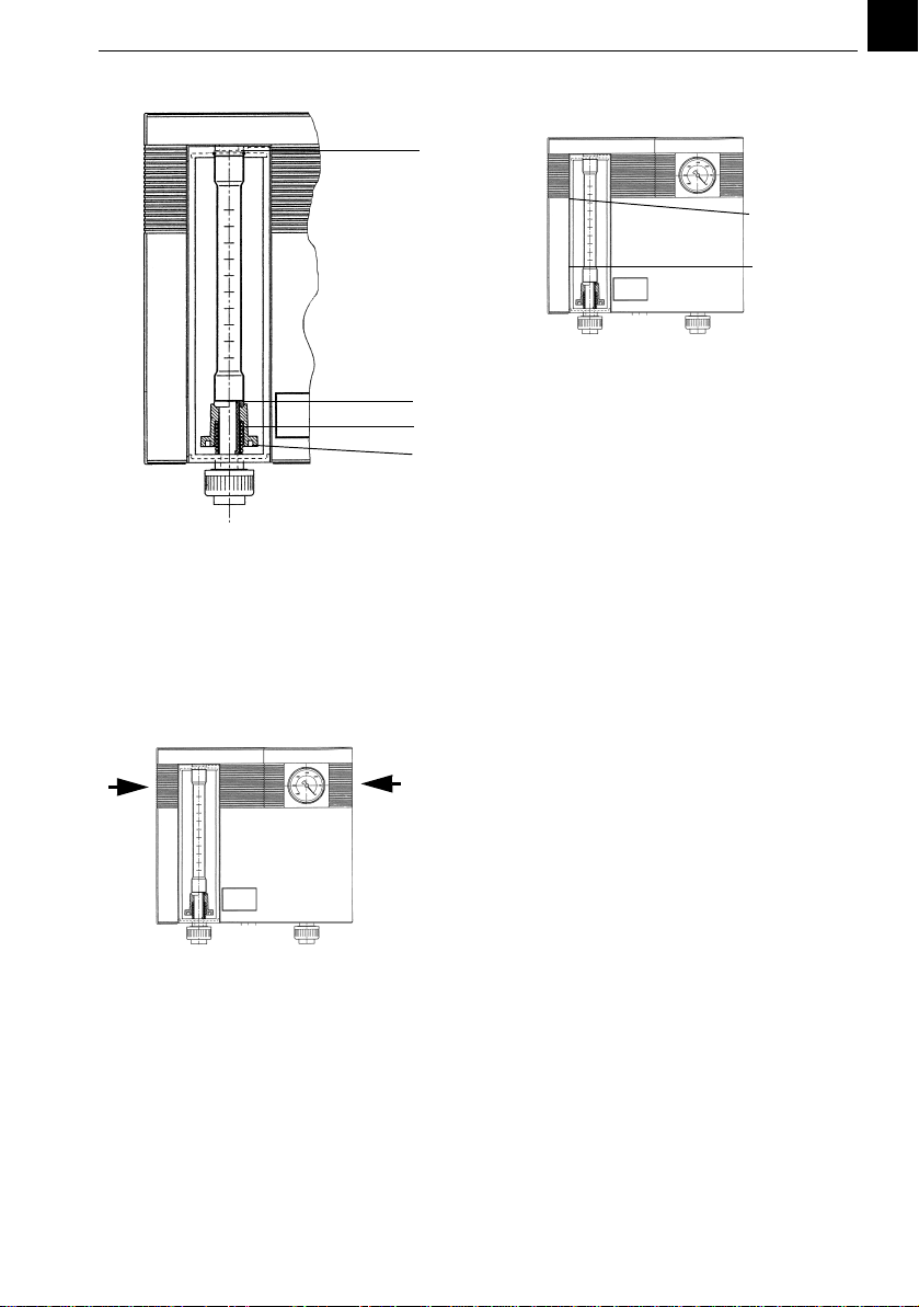
4.6 Insert the flowmeter
(preferably only immediately before commis-
sioning to avoid damage to the flowmeter)
1 Mount the spring and the socket from the
accessories set.
2 Apply some silicone grease to the two 'O'-
rings and place them into the grooves.
3 Hold the flowmeter tube in the middle,
the high values at the top, the tip of the
float pointing to the bottom.
4 Place the flowmeter tube onto the lower
'O'-ring, the high values of the scale on
top, press down the lower seat with two
fingers of the other hand, if necessary
press down the lower 'O'-ring with the
flowmeter tube.
5 Position the tube into the upper seat, turn
the tube until the scale is in front and
slowly release the lower seat. Hold the
tube until the tube safely rests on the o-
rings.
NOTICE
With this setting, only the desired, reduced
control range from the zero setting to the
reduced max. end switching point is availa-
ble in Automatic mode. In Manual mode, it
is still possible to set a dosing rate above the
reduced max. end switching point, up to the
maximum possible dosing rate (mechanical
end stop of the connecting rod).
ATTENTION
Switchover from Manual to Automatic mode
may only be carried out with the controller
in fully closed position!
V10k automatic 4. Installation
17
EN
A’O-ring
BLowerseat
C Socket and spring
4.7 Remove and mount the cover
1 Hold the cover at both sides, press your
thumb on the manometer and pull away
the cover at both sides at the same time.
1 Slide the cover over the T-shape rails (A)
of the body.
2 Press left and right until the cover is level
with the manometer and locked.
4.8 Preparation
Chlorination plants should be checked by a
specialist for condition according to the rules
before being taken into operation. Especially
the chlorine parts of the plant must be che-
cked for leaks.
When all the connections have been made,
the following pre-start checks must be carried
out before the plant can be taken into opera-
tion.
4.8.1 Check for water leaks
1 Close the regulating knob of the positio-
ner by hand or by the control.
2 Ensure that the gas cylinder or drum val-
ves are closed.
3 Open the stop valve at the point of appli-
cation.
4 Open the stop valve and the solenoid
valve in the water supply.
5 If installed start the booster pump.
6 Adjust the injector inlet pressure so that
the operation vacuum of 200 mbar is
displayed at the pressure gauge of the
V10k.
7 Check the water supply and the chlorine
solution line for leaks. Repair if necessary.
A
A
B
C
A
A

4. Installation V10k automatic
18
EN
4.8.2 Check for gas leaks
1 Keep the valves on the chlorine cylinder
or drum closed.
2 Open the valves in the water supply line
to the injector and at the point of applica-
tion. A vacuum of min. 200 mbar must be
indicated on the manometer of the cont-
rol unit.
3 Check that the flowmeter float remains at
his bottom stop. Any movement of the
float indicates an ingress of air on one of
the following locations:
• through the safety relief valve
• through the o-ring on the bottom of
the flowmeter or
• through cracks in the flowmeter
• through the o-rings at the pipe con-
nections
• through any incorrectly cemented
joints or slack unions in the pipework.
Repair any leaks immediately.
4 Open the valves on the chlorine cylinder
or drum carefully and close again.
5 Check for leaks. Hold a bottle of 25%
ammonia solution in the vicinity of the
part under test. In case of a leak the esca-
ping gas will form dense white clouds.
6 In case of a leak check that the cylinder or
drum valve is closed. Open the auxiliary
valve(s). Let the operating water flow.
Open the regulating knob of the positio-
ner and let the gas from the gas lines be
sucked away until the float in the flowme-
ter of the V10k is down on the lower stop.
Immediately tighten the leak.
7 When all parts have been checked:
Open the valve on the chlorine cylinder or
drum again.
8 Adjust the desired dosing capacity. The
operation vacuum is shown on the pres-
sure gauge of the V10k.
9 Close the valves on the chlorine cylinder
or drum. Within a minute the float in the
flowmeter of the V10k should be down on
the lower stop. Otherwise refer to step 2.
4.9 Commissioning
4.9.1 General
When the water and gas leak test have been
performed successfully, the system can be
started as follows (the positions refer to the
drawing in chapter 3.3)
1 Activate the gas warning device.
2 Open the point-of-application
3 Open the operating water valve incl sole-
noid valve.
4 If necessary start the booster pump.
5 Adjust the injector water pressure at the
reducing valve
6 Open the gas cylinder valve (3) one turn.
7 Open the vacuum control valve (4).
8 Adjust the dosage manually, read the
dosing rate at the flowmeter of the V10k.
9 Switch the positioner to automatic opera-
tion (knob pushed in), set the control to
the suitable dosage rate.
10 Check that the dosage rate on the control
corresponds with the display on the flow-
meter. For further information see the
instruction manual of the control.
WARNING
Danger due to chlorine gas !
Chlorine gas irritates the respiratory tracts.
Contact with chlorine gas in high concentra-
tions irritates and damages the membranes,
respiratory system and the skin. In extreme
cases death can result due to suffocation.
When inspecting the system for leakage
always keep your gas mask to hand.Practice
use of the mask regularly.
If chlorine gas is discharged, only use a gas
mask which is independent of ambient air!
Do not tolerate any leakages in the chlorine
system.
Before servicing the system the gas supply
must be closed off directly on the gas cylin-
ders or tank and the chlorine gas in the sys-
tem must be consumed completely. In case
of strong chlorine smell put on your gas
mask.
WARNING
Danger due to chemicals !
Testing for chlorine or SO2 gas leaks is
accomplished by introducing ammonia
fumes to the area under test. Any escaping
gas will combine with the ammonia to form
dense white clouds. Liquid ammonia solu-
tion must not be applied directly to the part
being tested. Hold a bottle of 25% ammonia
solution in the vicinity of the part under test.
Ammonia must not be inhaled, splashed or
spilled.

V10k automatic 4. Installation
19
EN
4.10 Training the operator
1 Train the operator for understanding at
least in safety, operation and fault finding.
NOTICE
The operator of the overall system must
ensure that only authorized and qualified
personnel can work on or with the system,
and within their specified area of responsi-
bility.
All personnel who work on the system must
have read and understood the instruction
manual, especially the safety instructions..

5. Operation V10k automatic
20
EN
5. Operation
5.1 General
If the chlorinator is installed and adjusted cor-
rectly, only the following measures are neces-
sary during operation:
• Check and adjustment of the dosage rate
• Dayly check of tightness
• Function check of the gas warning device
• Change of the gas containers
• Cleaning the strainer in the operation
water line.
• When testing the sprinkler system take
care that the gas cylinders and armatures
don’t get wet unnecessarily. Slip a hose
over the spray nozzles and lead the water
into the sink.
5.2 Start dosing
1 Check that the gas monitoring system is
activated.
2 Open the operating water valves and the
point-of-application.
3 Open the gas supply valves.
4 Open the vacuum control valve.
5 Adjust the dosage
• manually with the knob on the posi-
tioner
• or with the control (the knob must be
pressed).
5.3 Stop dosing
• Close the operating water valves or
• Close the gas supply valves or
• Close the vacuum control valve or
• Stop the dosage
• manually with the knob on the posi-
tioner
• or with the control (the knob must be
pressed).
5.4 Changing gas containers
1 Close the valve of the empty chlorine
cylinder.
2 Close the vacuum control valve (or the
auxiliary valve).
3 Remove the vacuum control valve (or the
auxiliary valve) from the chlorine cylinder.
4 Remove the empty chlorine cylinder,
place and secure a full cylinder.
5 Connect the vacuum control valve (or the
auxiliary valve) to the cylinder valve, using
a new gasket.
6 Open the cylinder valve for a moment and
close again, check for leaks.
7 Open the cylinder valve if the connections
are tight.
8 Open the vacuum control valve (or the
auxiliary valve).
5.5 To stop for extended periods
or maintenance
1 Turn off the gas cylinder valve.
2 Allow the control unit to operate until the
flowmeter float remains on the bottom
stop.
3 Turn off the water supply to the injector.
The manometer pointer comes down to 0.
4 Against frost remove all the water from
the water supply and solution line.
WARNING
Danger due to chlorine gas !
Chlorine gas irritates the respiratory tracts.
Contact with chlorine gas in high concentra-
tions irritates and damages the membranes,
respiratory system and the skin. In extreme
cases death can result due to suffocation.
When changing gas containers always put on
your gas mask.
WARNING
Danger due to chemicals !
Testing for chlorine or SO2 gas leaks is
accomplished by introducing ammonia
fumes to the area under test. Any escaping
gas will combine with the ammonia to form
dense white clouds. Liquid ammonia solu-
tion must not be applied directly to the part
being tested. Hold a bottle of 25% ammonia
solution in the vicinity of the part under test.
Ammonia must not be inhaled, splashed or
spilled.
Other manuals for V10K
2
Table of contents
Other Evoqua Industrial Equipment manuals


Popular Industrial Equipment manuals by other brands


TTM
TTM MAG 250 Installation, Operating and Maintenance Instruction

Evenheat
Evenheat Glass Kiln GTS 18 General operations manual

Graco
Graco Series A Instructions-parts list

Jäger
Jäger Z33-D060.52 S21 manual

HMF
HMF 6750-76MM instruction manual

KMT
KMT STREAMLINE SL-V SRP 100 Operation and maintenance manual

PCB Piezotronics
PCB Piezotronics 353B14 Installation and operating manual

Stahl
Stahl SolConeX 8573/14 Series operating instructions

MSW
MSW WIRESTRIPPER-002-1500 user manual

Rockwell Automation
Rockwell Automation B Series user manual

MORKO
MORKO USP-300-AT manual

Mayr
Mayr EAS-Sm Installation and operating instructions