EVPORT EVC1S-3210 User manual

Model: EVC1S-3210
EVC1L-3210
READ AND SAVE THESE INSTRUCTIONS
Installer: Leave this manual with the homeowner
ELECTRIC VEHICLE CHARGER
COD:0030300000-A

TABLE OF CONTENTS
SAFETY INSTRUCTIONS
INDICATOR LIGHT
CONNECT ELECTRICAL WIRING
WARNING
INSTALLATION
UNPACKING
TOOLS/MATERIALS REQUIRED
FUNCTION INSTRUCTION
BEFORE INSTALLATION
INSTALLATION LOCATION
INSTALLATION INSTRUCTIONS
USER INSTRUCTIONS
3
4
4
5
6
7
6
7
8
8
8
9
9
10
14
14
22
PRODUCT DESCRIPTION
INSPECTION
SET THE CHARGER POWER
APP INSTRUCTION
MAINTENANCE
5PRODUCT DIMENSIONS
ATTACHMENT 7
16
16
18
21
15INSTALLATION OF THE CABLE HOLDER
16
23
TROUBLESHOOTING
PARAMETERS SHEET
OPERATE INTRODUCTION
REGISTER
ADD DEVICE
FAULT INTERFACE

3
SAFETY INSTRUCTIONS
Important note: Please read this booklet before installing and switching on this appliance. The manufacturer
assumes no responsibility for incorrect installation and usage as described in this booklet. Keep the instruction book
for future reference. All the information in the manual is valid for the charging station model in this manual.
This instruction book details the install guidance for the charger. If you’re unsure which model you have, please
check the rating label on the charger.
The unit is designed for installations inside or outside, with the Innovative safety systems we have built into the
charger ensuring its safe usage. This guidance provides information to assist when installing the unit. The charger
must be professionally installed by a qualified electrician according to local and national regulations applicable at the
time of installation and used in accordance with the manufacturer’s instructions.
●This unit must be grounded (Earthed).
●This unit is only to be installed by a qualified electrician in accordance with local building and electrical codes and
standards.
●This unit is designed to connect a electrical supply voltage of AC220V~240V 50/60Hz for single phase series.
●The charger must be installed on a secure solid surface that can support the weight of the charger. Failure to
install on a secure surface or not in accordance with electrical regulations could lead to death, personal injury, or
property damage.
●This appliance is designed to be used by adults, do not allow children to play with the appliance or let them hang
over the charger.
●Do not put fingers into the socket or connector.
●
This unit is not suitable for use in dangerous places where there is high amounts of dust, dangerous gas or in an
explosive and flammable environment.
●In order to ensure the electrical safety of the unit, the product body shell must be fixed to the correct position with
fasteners that come with the product and the seals used to ensure the IP rating is maintained.
●The unit’s inlet position (front face) must be tightly sealed to be waterproof and dustproof to ensure the products IP
rating.
●Do not use this unit other than its intended purpose.
●Do not use if the socket or connector or cable is damaged.
●Disconnect the charging from the vehicle prior to driving off.
●To prevent electrical shock, do not plug-in or un-plug with wet hands .
●Do not use a power washer to clean or wash the car charger.
●It is recommended not to use in a location that can be reached by rain, suggest increase rain protection measures.
●Do not install in areas of high-risk chance of impact by vehicles or a high risk of trip hazard.
Important: Under no circumstances will compliance with the information in this manual relieve the user of his/her
responsibility to comply with all applicable codes or safety standards.
4
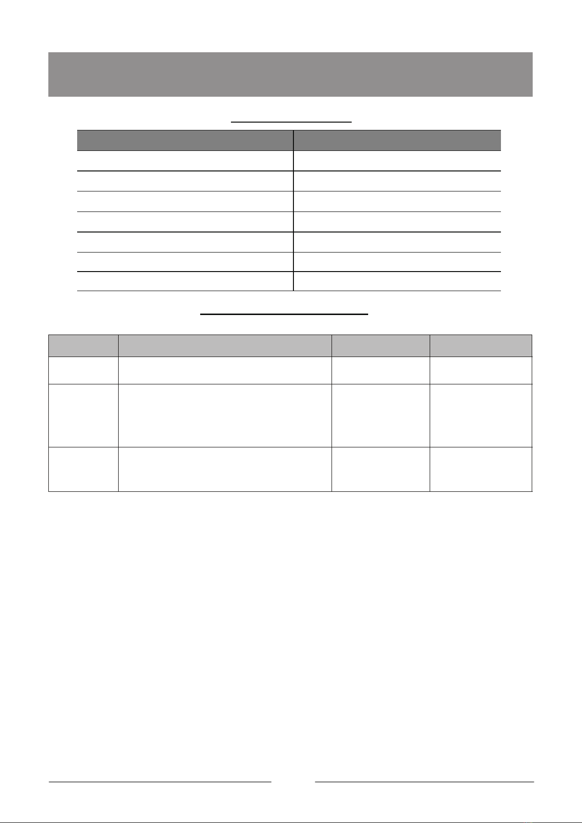
PARAMETERS SHEET
USER INSTRUCTIONS
Item Datasheet
Model
Power Supply
Rated Voltage
Rated Current
Output Voltage
Maximum Current
Rated Power
ABS +PC Flammability Rating V - 0
White + gray
Three colour LED
Charger Socket
or Connector
Material
Colour
Indicator Light
Ingress
Protection
EVC1S-3210
AC220 ~ 240V
50/60Hz
7.4KW
IP54
Over current protection
The max 32A-Recommended 36A
Residual current protection
(AC 30mA, DC6mA)
Earth check
Over/Under voltage protection
Over temperature
Certification CE, UKCA, CB
Certification
Standard EN 61851,EN 62196
Input
Output
User
Interface
Safety PCB Protection
Power
Consumption
Standby Power
Consumption <10W
Installation Wall mounted
Work Temperature -25℃~50℃
Work Humidity 3%~95%
Work Altitude <2000m
Enviroment
EVC1L-3210
1P+N+PE
AC220 ~ 240V
50/60Hz
Max 32A
(6-32A adjustable)
Max 32A
(6-32A adjustable)
Enclosure: IP65
Connector:IP54
Type 2
5
USER INSTRUCTIONS
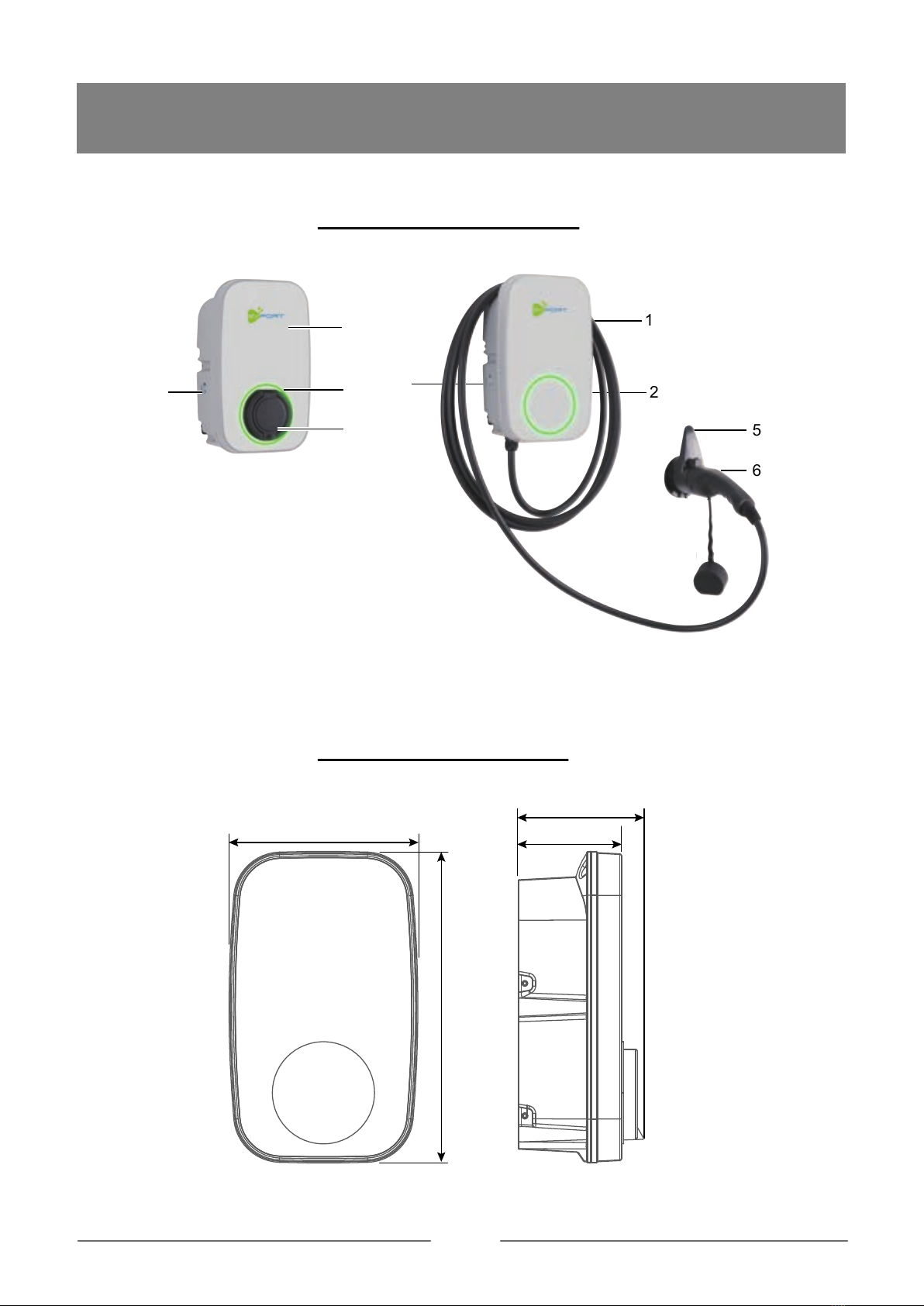
PRODUCT DIMENSIONS
PRODUCT DESCRIPTION
330mm
200mm 109mm
132mm
1
2
3
4
1
2
4
5
6
1. Front cover
2. Working status indicator
3. Socket
4. Function button
5. Charger holder
6. Charging cable and connector
6
INDICATOR LIGHT
Light Display Status Product Status
Blue, green and red flashing alternately Product power-on self-check
Blue light glowing Standby
Blue light flashing
Green light glowing Charging
Green light flashing Disconnect charging from APP or OCPP
Red light glowing Over temperature
Emergency stop
USER INSTRUCTIONS
Connection confirmation
Red light flashing one fast, one slow
FUNCTION INSTRUCTION
Function button operation instructions
Red light flashing
One fast, one slow
Emergency
stop
Mode
toggle Beep twice
If you want to cancel
the plug and charge
mode,click schedule
in the APP
Beep twice
The charger will need
to be readded to the
APP
Wifi reset
On standby statue, press and hold for more
than 10 seconds to reset the WiFi, then
re-add the device for pairing connection
During normal charging, press once
On standby statue:
Under APP control mode, press 5 times continously
to enter plug and charge mode;
Note: plug and charge mode: automatically
confirmed charging after the connection is confirmed.
Un-plug the connector
Operation Status indicators Remark
Function
7
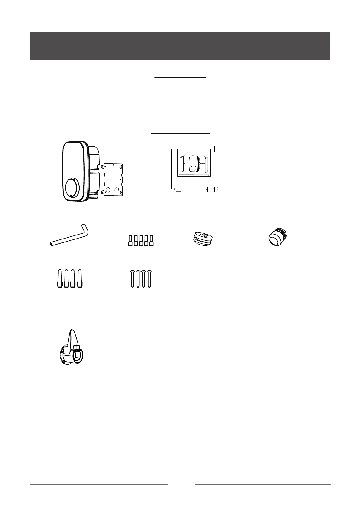
1.Scratch or remove the sealing tape and take out the unit.
2.Follow the ATTACHMENT to check all items and to see if there are any omissions.
3.Check the unit is correct and whether it matches with order model.
4.Check whether the unit has defects or is damaged due to defectiveness or transportation.
5.Make sure all packaging is disposed of responsibly and in accordance with the current regulations in your region.
1 x Installation template
1 x Cable Gland1 x Sealing rubber
4 x Wall Plugs
M6x30
4 x Screw
ST4.2x32
Wiring cap
1 x EV Charger & 1 x Fixing bracket *
1 x Elbow wrench
ATTACHMENT
UNPACKING
electric vehicle charger
1 x Manual
INSTALLATION INSTRUCTIONS
* NOTE: It is integrated from factory, and separated when installed.
** Just for connector and cable charger.
1 x Charger holder**
There should be a certain space around the machine for
installation and future maintenance
141.2mm
140.2mm
24.5mm
2.1mm
aa
Wall or other fixed objects that cannot be moved
SUGGESTION: a (side gap): minimum 250mm
The cable entry hole
(for mode 2)
1. This unit must be grounded.
2. This unit should be installed by a qualified electrician in accordance with
local building regulations, electrical codes standards, climate conditions,
safety standards, and all applic-able codes and ordinances.
WARNING:
Installation location
Mounting hole:
4-Φ6*35

8
TOOLS/MATERIALS REQUIRED (NOT INCLUDE)
Measuring tape
PencilPhillips screwdriver Slotted screwdriver
Electric elbow toolSafety glovesElectric drill
1. Installer or end user must read and understand all the content covered in
this manual before installing or using this unit.
2. Choose a suitable installation location according to the installation conditions stated in the warning.
3. Make sure that the installation location complies with current laws and
regulations.
4. Confirm that there is a suitable input voltage power supply at the installation site (consistent with the nominal
power supply of the product).
5. Make sure the supplied fixings are suitable for the mounting location. If not suitable, alternatives must be
obtained locally before proceeding with the installation.
BEFORE INSTALLATION
INSTALLATION LOCATION
INSTALLATION INSTRUCTIONS
There should be a certain space around the unit for
installation and future maintenance.
SUGGESTION:
a (side gap): minimum 250mm.
*A charging cable holder position needs to be reserved.
(Just for connector charger and cable)
Hole Saws
Mode 1: Φ24mm Bottom hole
Mode 2: Φ18mm (Back hole for
Sealing rubber)
aa
Wall or other fixed objects that cannot be moved

9
Bottom entry
(Best choice) Back entry It is strictly forbidden to pass the
bottom line through the back.
CONNECT ELECTRICAL WIRING
Important:
Before installing the unit, it necessary to confirm the way of the product's power cable entry. Mode 3 power
cable entry is strictly prohibited.
▲ Make sure that the power source is turned off before installing the unit.
▲ Manufacturers and distributors are not responsible for any loss or related responsibilities caused by any
incorrect installation.
▲ The installer shall be responsible for the loss and damage of the product, system or property caused by
improper installation.
WARNING
INSTALLATION INSTRUCTIONS
Mode 1 Mode 2 Mode 3
Cable Cable
√√
×
Sealing rubber
Cable Cable Gland
Note: The charger must be electrically protected by installing externally a Miniature Circuit Breaker (MCB) and
a Residual Current Circuit Breaker(RCCB).
MCB: Maximum value according to the maximum output current of the load point.
Reference SET THE CHARGER POWER.
RCCB: According to local regulations, Type A or Type B.
1
1. DIP switch
Socket/
Connector
PE N-IN
L-IN
N-OUT PP CP
L-OUT
L
N
PE
L (Brown)
N (Blue)
PE (Yellow/green)
CP (Black or Orange)
PP (Grey or White)
CT
LIGHT
Button
Terminal
RCD1
AC220V~240V 50/60Hz
10
INSTALLATION
INSTALLATION INSTRUCTIONS
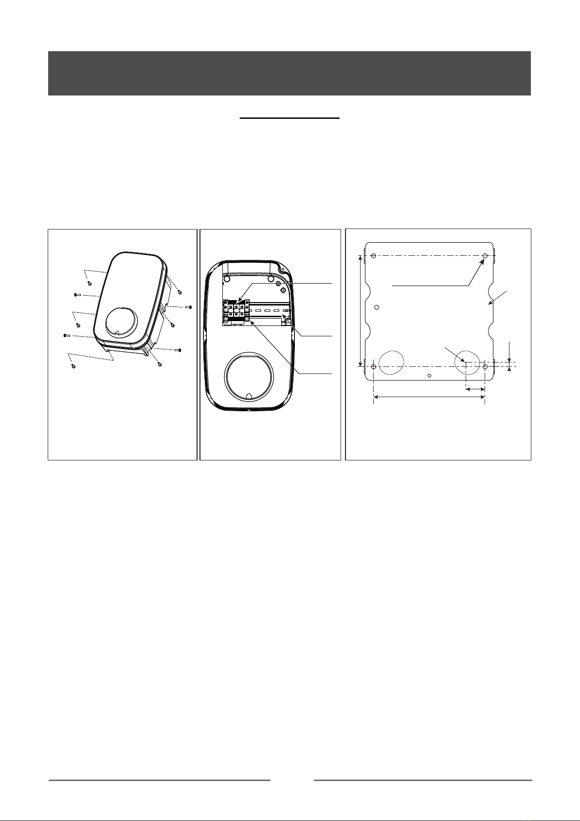
1. Take the unit and remove the 4 screws on its fixing bracket (The unit is integrated with the fixing bracket and
needs to be disassembled first). Keep the screws and fixing bracket for subsequent use;
2. Remove the 6 fixing screws on the front shell and the rear shell, save the screws for subsequent use;
Note: Reference Fig.1 for steps 1 and 2.
3. Open the front shell carefully. The front shell is connected to the unit body through a cable. Be careful not to
damage or break the cable.
Caution: After opening the front shell, visually inspect the inside. If the wiring terminal block or the fixed compo-
nent falls off the track, it can be installed back to the track by itself (reference Fig. 2)
4. Inlet wire mode 1: use the installation template to mark the fixed bracket installation hole position.
Inlet wire mode 2: use the installation template to mark the position of the fixing bracket installation hole and
the cable entry hole.
Note 1: Inlet wire mode 2 which need to pay attention to the correct direction of the installation template.
Note 2: Make sure that the installation template itself is level when the position is marked.
Note 3:Refer to Installation template.
5. Punch holes according to the punching information prompted by the installation template, and ensure that the
punch positions are accurate.
(1). Fixed bracket mounting hole has a diameter of 6mm and a depth of about 35mm.
(2). Inlet wire mode 2, diameter of the cable entry hole needs to be defined according to the actual cable
selection, However, it is recommended that the maximum opening diameter should not be bigger than 24mm.
Caution: The edge of the wall opening needs to be repaired, and it must not be a sharp edge to prevent the
incoming wire from being cut.
6. Fixing bracket installation hole inner - insert wall plugs, and use attachement screws(ST4.2*32) fixing fixed
bracket to the mounting surface and ensure the screws are fastened well.
Note: If the screws are not fastened well, the fixing bracket may become loose and may interfere with the
installation of the housing.
a
a
a. 4 x fix bracket fix screw
b. 6 x Front & rear shell fixed screws
Fig. 2
Fig. 1
a
b
a
fixed
components
track
terminal
block
b
b
b
b
b
unit: mm
The cable entry hole
(for mode 2)
* The installation method 2 in the cable entry
template is used for the rear entry of the cable.
140.2
Fixing
bracket
141.2
24.5
2.1
Mounting hole: Φ6*35
11
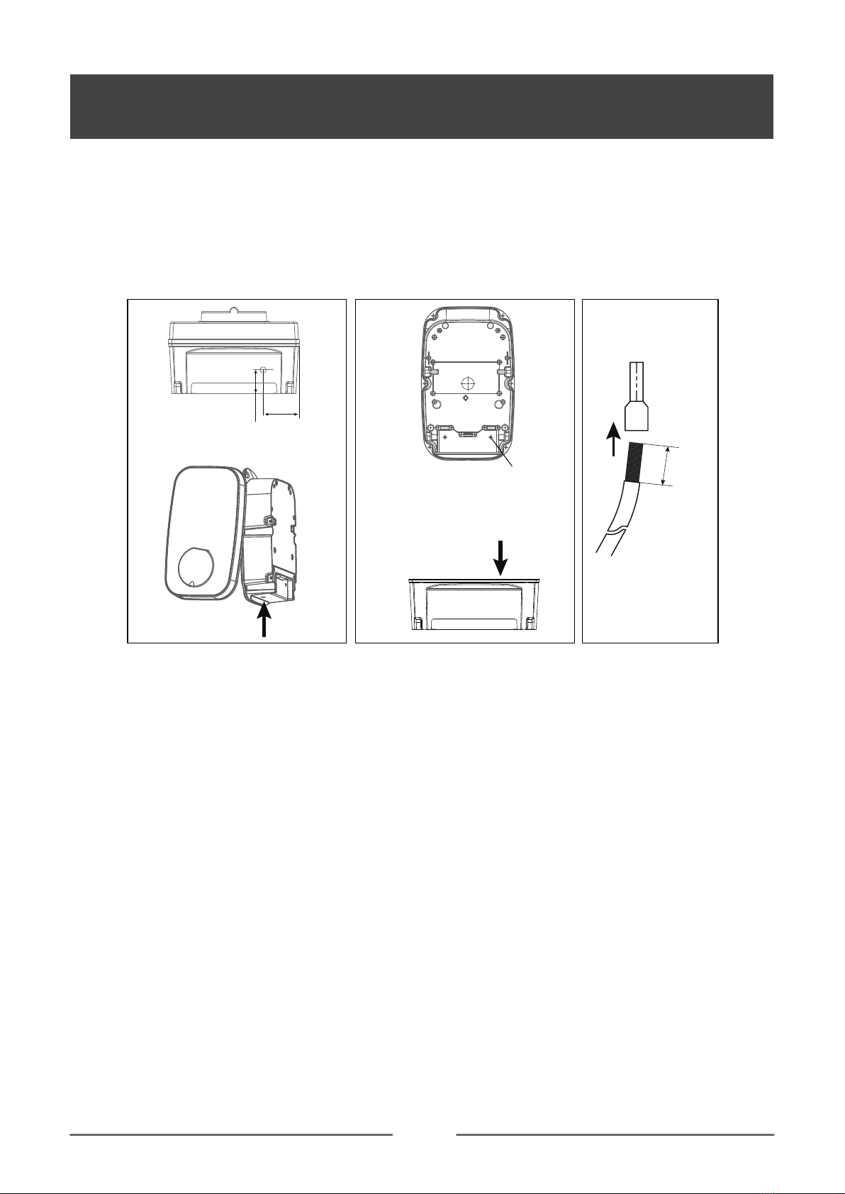
INSTALLATION INSTRUCTIONS
NOTE 1: Inlet wire mode1, open hole size must be accurate, and the hole diameter is 24mm(for the single
phase).
NOTE 2: Inlet wire mode 2, open hole size must be accurate, and the hole diameter is 18mm.
WARNING: Remove burrs around the hole to prevent affecting the seal level.
WARNING: Do not damage internal components, especially internal wiring, when drilling the hole.
8. Clean and remove all the debris that has fallen into the shell due to the punching.
9. Inlet wire.
Punch hole position
Inlet wire mode 1
Punch hole position
Inlet wire mode 2
Drilling
direction
12mm
In
Wiring cap
Fig. 4
Cable
39mm
50mm
Drilling direction
Drill position
7. According to the size and position below, open the power cable hole on the shell.
* NOTE: Product installation details with power management. Refer to “Power management function installa-
tion guide”.
12
INSTALLATION INSTRUCTIONS
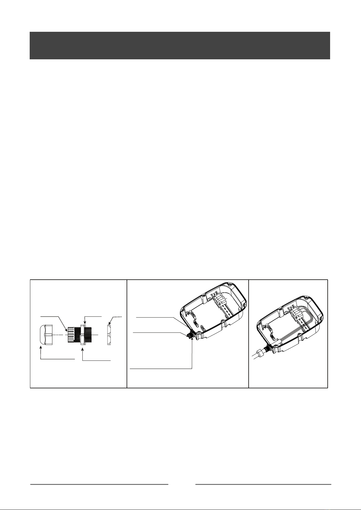
MODE 1
a1. Check the cable gland parts as shown in Fig. 5.
a2. Pass the gasket and the main body through the opening hole of the shell and lock it with a nut, as shown in
Fig. 6.
a3. Insert the pressing head into the cable, and then thread the cable into the main body that cannot be pulled
off, as shown in Fig. 7.
a4. Trim and cut the cable to the proper length, lock the pressing head to secure the cable.
a5. Refer to this article connect electrical wiring to connect the cable to the terminal block.
NOTE: connecting wiring reference Fig. 4
WARNING: To ensure the rated IP protection level of the product, must use the cable gland in the accessories.
a6. Confirm and remove the debris inside the housing caused by punching and wiring.
a7. Ensure that all cables are connected correctly and securely, and are not loose or damaged.
a8. Screws lock the front and rear shells tightly.
Caution: Need to use the screws removed from the original position.
Before installing the front shell, it must be ensured that the sealing strip in the front shell groove has not fallen
off and is in the right position. Ensure that all seals performed on the unit can reach the IP rating.
a9. Screw the unit to the fixed bracket.
Caution: Use the screws removed from the original position.
Note: a8, a9 refer to Fig. 1, reverse operation.
Fig. 5 Fig. 6
Pressing head
Built-in
sealing ring
Main body
Gasket Nut
Fig. 7
Pass the gasket and the main
body through the opening
hole of the shell
The built-in sealing ring
must not fall off
lock it with the nut

13
INSTALLATION INSTRUCTIONS
MODE 2
b1. Insert the sealing rubber into the housing, as shown in Fig 8, insert the bare wire into the sealing rubber, one
hole corresponds to one bare wire, after all the wires are inserted, leave enough length of the cable to connect
to the terminal block.
NOTE1: To ensure the rated IP protection level of the product, must use the sealing rubber in the accessories.
NOTE2: Poke the middle position of the sealing rubber before installing this item.
b2. Screw fastening the entire rear shell to the fixing bracket.
Caution: Use the screws removed from the original position.
b3. Refer to this article connect electrical wiring to connect the cables to the terminal block.
NOTE: connecting wiring refer to Fig. 4
b4. Seal the opening on the back to achieve the unit’s IP rating.
Warning: sealing is very important. This involves the safety of the product and must be paid attention.
b5. Screws lock the front and rear shells tightly.
Caution: Use the screws removed from the original position.
Before installing the front shell, it must be ensured that the sealing strip in the front shell groove has not fallen
off and is in the right position.
Make sure that all seals performed on the unit can reach the IP rating.
Note: if there is no suitable electric tool, the elbow wrench provided in the accessories can be used to tighten
the screws of the front and rear shells.
IMPORTANT NOTE: It is the responsibility of the installing engineer to satisfy themselves, that all cable termi-
nations throughout this product are secure and tight and have not become loose, strained, or disconnected
during transit and/or installation.
After the front and rear shells are installed, check whether there is a loose gap between the front and
rear shells. Make sure that there is no loose gap.
Fig. 8
Tuck the Sealing rubber into the housing from the outside in. Insert it
with angle level, allowing its seal groove to fit into the housing.
With angle level
14
INSPECTION
INSTALLATION INSTRUCTIONS
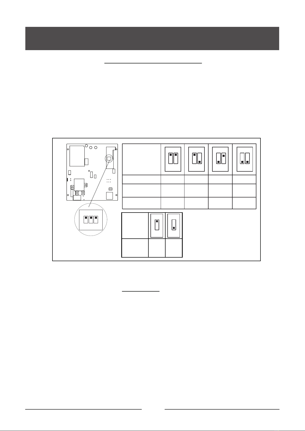
SET THE CHARGER POWER
You need to set the corresponding position of the current DIP switch according to the min. wire size shown in
the chart and the rated current of the Circuit breaker (factory setting 32A). refer to the steps below.
Caution 1: The following operations must be powered off.
Caution 2: Incorrect setting DIP may cause hazards such as overheating or fire of the incoming wire.
1. Locate the position of the two-position DIP switch on the power supply board, like picture.
2. Setting the switch to the desired position:
WARNING: Electrical Power Switches must only be set by a qualified electrical installer. Incorrect setting may
lead to equipment damage and / or personal injury. The current rating must not exceed the supply rating.
1. Check that this unit must be grounded (Earthed).
2.Make sure you are satisfied that the installation is complete and is in a safe condition.
3.Switch ON the power, which it will cycle the red, blue and green lights to self-check and then enter the
corresponding light indication. The unit and test in accordance with the current Electrical Wiring Regulations.
NOTE: Make sure this product has been installed in compliance with the
current Electrical Wiring Regulations.
1 2 3
ON
Earth
check Yes No
3
ON
3
ON
DIP switch
position
DIP switch
position
Current(A)
Min. wire size
(copper)
Circuit breaker
(Amps)
6mm²
or 10AWG
2.5mm²
or 13AWG
2mm²
or 14AWG
1.5mm²
or 15AWG
1 2
16
20
13
20
1 2
32
40
1 2
10
16
1 2
ON ON ON ON
15
INSTALLATION INSTRUCTIONS
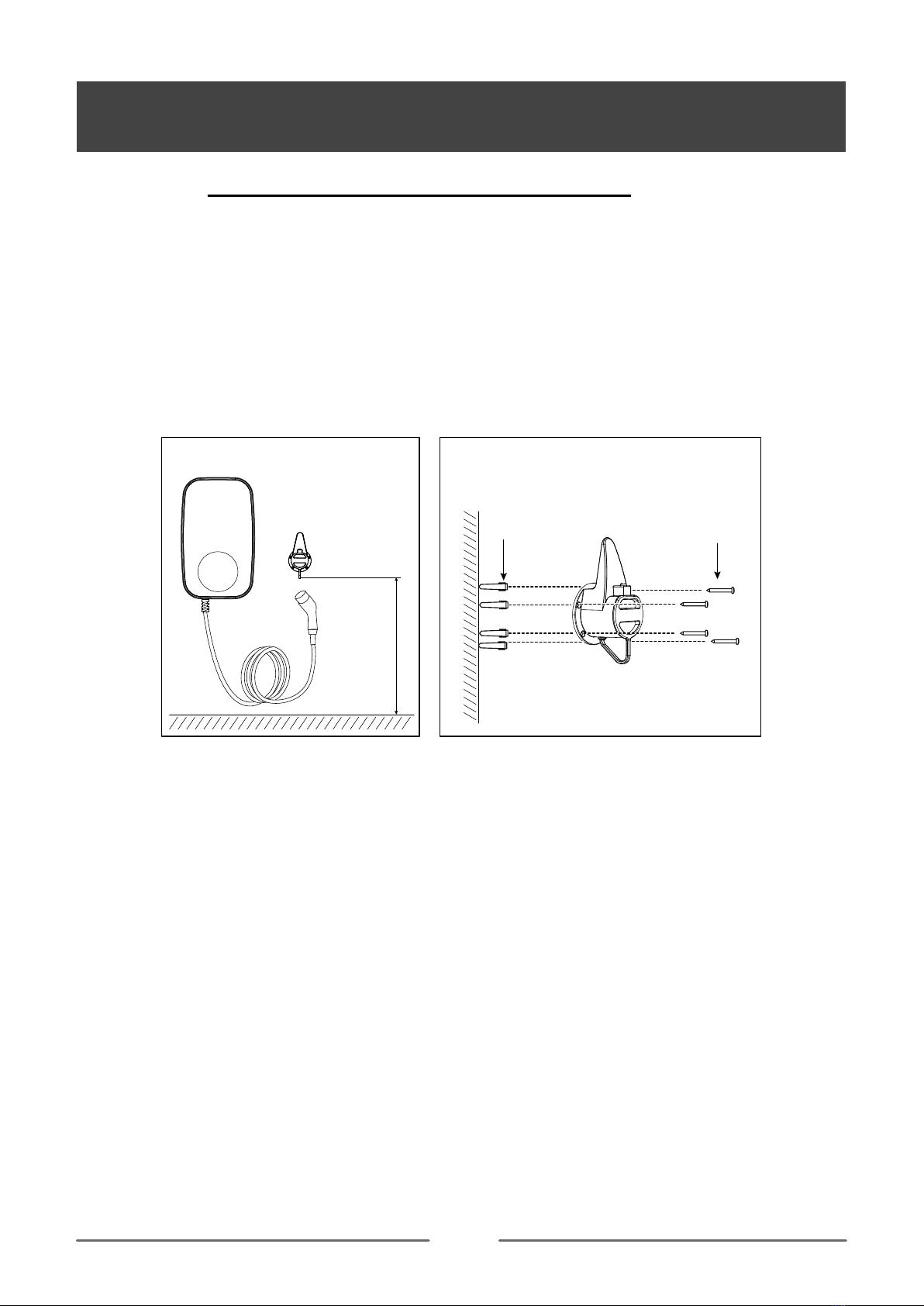
INSTALLATION OF THE CABLE HOLDER
JUST FOR EVC1L-3210
1. Take out the charger holder.
2. Find a suitable location near the EV charger box, which must be more than 0.5m above the bottom surface
and not higher than 1.5m.
3. Align the charger holder in position and mark the four mounting holes.
4. Drill the 4 holes as the marks at dia 6mm, 35mm deep.
5. Insert the wall expansion plug.
6. Screw the charger holder to the wall.
7. Installation is complete.
0.5m < height < 1.5m
Wall Plugs
M6*30
Screw
ST4.2*32
16
APP
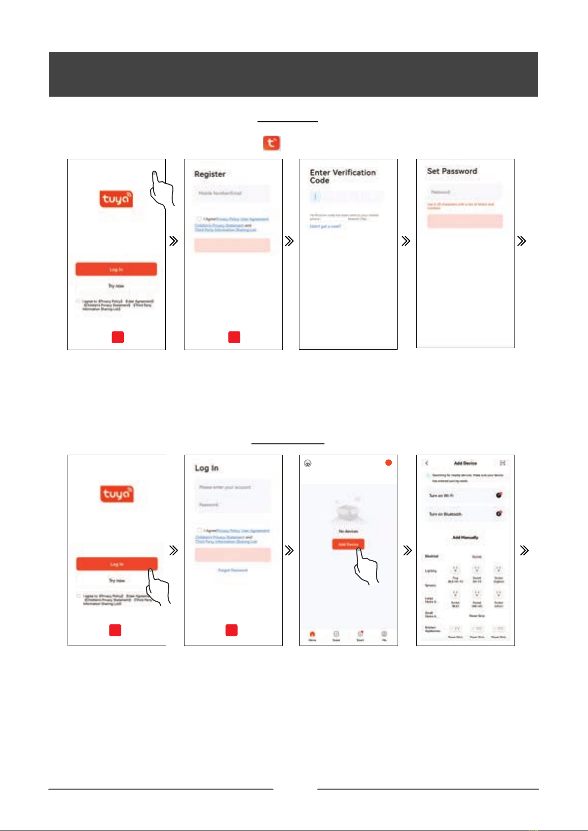
Register
APP INSTRUCTION
Step 2. Open the tuya app register an account to log in or log in directly through the relevant app bound by tuya.
Note: You can register your account through your mobile phone number or email. The following takes mobile
phone number registration as an example to describe the steps in detail:
REGISTER
ADD DEVICE
Step 2-1: Click Register Step 2-2: Check the app
agreement, enter the registered
mobile phone number and click
to get the verification code
Step 2-3: Input verification code.
APP
Step 3-1: Click log in Step 3-2: Check the app agreement,
enter the registered account and
password, and click log in.
Step 4: Add device. Step 5: Network and bluetooth
not turned on.
Step 2-4: Input the account login
password and click done to
complete the registration.
APP
Register
+
APP
Step 1. Application platform download Tuya app .
**-**********
Step 3. Check the app agreement, click log in, input the newly registered account and password to log in to the
tuya app, and complete the app log in.
Step 4. Reset wifi(refer to the function button instruction for the wifi reset operation guide),Click “Add Device” to
add the charger device that needs to be connected.
Note: Make sure the connector un-plug before add the device.
Step 5. After turning on wifi , bluetooth and geolocation, the tuya app automatically searches for connectable
devices.
Note 1: When connecting the device,the mobile phone must be close to the charger.

17
APP INSTRUCTION
Step 8: Click the corresponding device. Step 10-1: Default selection interface Step10-2:Device control interface
Step 8. Click the relevant device icon to enter the device control interface.
Step 9. The first connection will appear the default selection interface, you can select the default mode, edit
the charging time or select the manual mode.
Step 10. Click manual mode.
Step 11. After connecting to the electric vehicle, then charging without any operation.
Step 6. After clicking ADD, enter the wifi and wifi password, wait for the device to connect to the network.
Step 7. If you need define a new device name, click“ ” if not need, click “done” to confirm the connection is
successful.
Step 6-2: Enter wifi name and
password, then click the next
Step 6-3: Loading Step 7
Step 6-1: Click Add.
2.The charger needs to be connected to WiFi. If the WiFi signal is weak or absent, the charger will not
receive the signal or delay the connection. Therefore it is recommended to add an enhancement device for
WiFi receiving signal near the charger. Note: To check if your WiFi can reach the charger and have a good
signal check your smart device or smart phone whilst standing close to the charger with the WiFi tuned on if
the signal can be seen above 2 bars then it is ok if not a WiFi booster or repeater needs to be added. Note:
The ethernet port is not for the smart App it is only for OCPP use.

18
APP INSTRUCTION
01.00 12.00 24.00
OPERATE INTRODUCTION
1
3
6
7
10
14
15
2
4
8
11
13
12
9
5
Edit
Single charging
energy consumption
Charging state
Charging mode
CP state
Cumulative charging
energy consumption
Charging voltage
Charging current
Charging power
On/off
HOME
Charging mode
Record
Setting
Energy consumption record
1
3
6
7
10
14
15
2
4
8
11
13
12
9
5
INTERFACE INTRODUCTION
19
APP INSTRUCTION
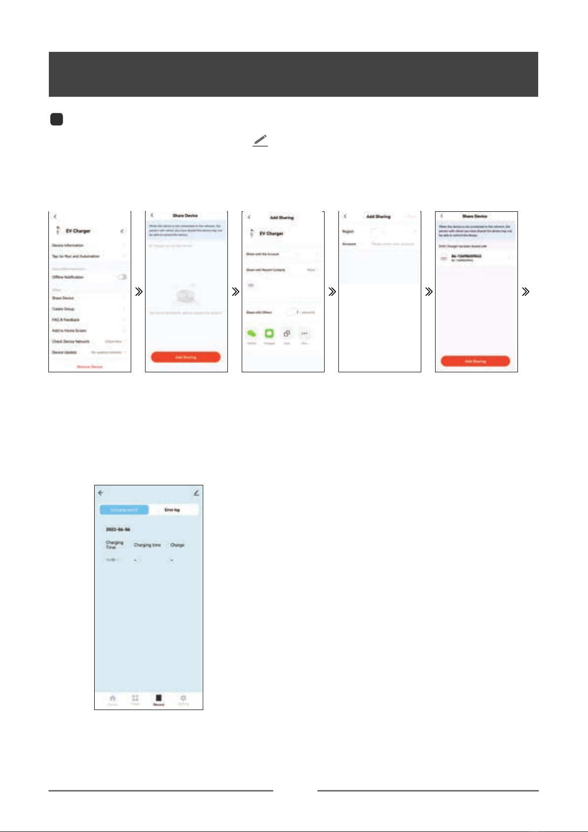
(1). You can set the charger name by clicking " "
(2). Offline Notification: When the charger is powered off, it will prompt the device to be offline on the home
screen.
(3). Share Device: You can share the APP with others by share device. Shared users only have the using right
and cannot share the APP again.
Refer to the following steps:
Step1: click“Share Device”. Step2: click“Add Sharing”. Step3: click“share with the
account EVEC”.
Step4: Input EVEC accunt
at account.
Step5: Done.
1Edit
(4). Software Update: When their is a software update available a message will appear on the APP screen to
confirm the update.
(5). Remove Device
1. Disconnect:Disconnect device connection.
2. Disconnect and wipe data:Disconnect device connection and wipe “Charging record” and “Error Log”data .
Jimmy
****

20
APP INSTRUCTION
Set time point
Date choose
Remark info.
Alert reminder setting
Charging on/off
Hours setting
(1).manual mode:control charger by Enable and Turn off charger on APP.
(2).Schedule: Timed charging.
NOTE 1: When you choose the set time point to turn on the charging , you must adjust the hours setting,
otherwise the default charging time is only 1 minute;
2: When you choose the set time point to turn off the charging, there is no hours setting;
3: When you choose the date choose, this time of each week will default to on or off charging.
You can view “Charging record” and “Power” on this interface.
NOTE:Only the information that is turned on or off through the APP will be recorded in the charging record.
When the charging is turned on by the function button, there is no charging record.
14 Record
Charging mode Charging mode
13 Charging mode
Record
This manual suits for next models
1
Table of contents


