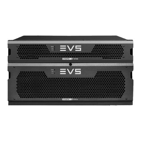
EVS Synapse MGU100 User manual

Synapse
MGU100 - MGG100
4K (MGU100) / 3Gbps (MGG100), HD, SD SDI
Eightfold Multiview Building Block (ACP2 model)
Version1.00|December2021
INSTALLATION AND OPERATION MANUAL


Disclaimer
This manual and the information contained herein are the sole property of EVS Broadcast Equipment SA
and/or its affiliates (EVS) and are provided “as is” without any expressed or implied warranties, including,
but not limited to, the implied warranties of merchantability and fitness for a particular purpose. In
particular, EVS makes no warranty regarding the use or the consequences of use of this manual and the
information contained herein. Furthermore, EVS may not be held liable for any direct or indirect,
incidental, punitive or consequential loss, damage, cost or expense of any kind whatsoever and
howsoever resulting from the normal or abnormal use of this manual and the information contained
herein, even if advised of the possibility of such loss, damage, cost or expense.
While every effort has been made to ensure that the information contained in this manual is accurate,
up-to-date and reliable, EVS cannot be held liable for inaccuracies or errors that may appear in this
publication. The information in this manual is furnished for informational purpose and use only and
subject to change without notice.
This manual cancels and replaces any previous versions thereof.
Copyright
Copyright © 2003-2021 EVS Broadcast Equipment SA. All rights reserved.
This manual may not be reproduced, transcribed, stored (in a database or a retrieval system), translated
into any language, computer language, transmitted in any form or by any means – electronically,
mechanically, printed, photocopied, optically, manually or otherwise – in whole or in part without the
prior written consent of EVS.
Trademarks
All product and brand names are registered trademarks and trademarks of EVS or of their respective
owners.
Improvement Requests
Your comments will help us improve the quality of the user documentation. Please send improvement
Regional Contacts
You will find the full list of addresses and phone numbers on the following webpage:
https://evs.com/contact/offices.
User Manuals on EVS Website
The latest version of the user manual, if any, and other user manuals on EVS products can be found at
the EVS download center, on the following webpage: https://download-area.evs.com.
INSTALLATION AND OPERATION MANUAL
Synapse MGU100 - MGG100|Disclaimer| I

GeneralInformation
ALWAYS disconnect your entire system from the AC mains before cleaning any component. The product
frame (SFR18, SFR08 or SFR04) must be terminated with three-conductor AC mains power cord that
includes an earth ground connection. To prevent shock hazard, all three connections must always be
used.
NEVER use flammable or combustible chemicals for cleaning components.
NEVER operate this product if any cover is removed.
NEVER wet the inside of this product with any liquid.
NEVER pour or spill liquids directly onto this unit.
NEVER block airflow through ventilation slots.
NEVER bypass any fuse.
NEVER replace any fuse with a value or type other than those specified.
NEVER attempt to repair this product. If a problem occurs, contact your local EVS distributor.
NEVER expose this product to extremely high or low temperatures.
NEVER operate this product in an explosive atmosphere.
To reduce the risk of fire or electrical shock, do not expose this appliance to rain or moisture.
This product complies with the requirements of the product family standards for audio, video, audio-
visual entertainment lighting control apparatus for professional use as mentioned below.
EN60950 Safety
EN55103-1: 1996 Emission
EN55103-2: 1996 Immunity
This device complies with Part 15 of the FCC Rules. Operation is subject
to the following two conditions:
1. This device may cause harmful interference, and
2. This device must accept any interference received,
including interference that may cause undesired operation.
Tested to comply with
FCC Standards
FOR HOME OR OFFICE
USE
II| December 2021 | Issue 1.00.B

Contents
Disclaimer I
GeneralInformation II
Contents III
What'sNew? V
1. Introduction 1
2. UnpackingandPlacement 2
3. QuickStart 3
3.1. Changing Settings and Parameters 3
3.2. Using Cortex with Synapse 5
3.3. Daisy Chain Mode 6
4. TheMGU100/MGG100Card 9
5. GraphicalUserInterface 12
5.1. Window Layout Tab 12
5.1.1. Overview 12
5.1.2. Video, Clock and Notes Settings 14
5.2. Control Tab 20
5.3. Background Tab 23
5.4. Detection Tab 24
5.5. Network Tab 27
5.6. Input Status Tab 29
5.7. Window Status Tab 31
5.8. Output Status Tab 33
5.9. GPI Tab 35
5.10. Object Browser Tab 36
INSTALLATION AND OPERATION MANUAL
Synapse MGU100 - MGG100|Contents| III

What'sNew?
In the Installation and Operation Manual the icon has been added on the left margin to highlight
information on updated features.
No changes in version 1.00 of the MGU100 - MGG100 require an update to the current manual.
INSTALLATION AND OPERATION MANUAL
Synapse MGU100 - MGG100|What's New?| V


1. Introduction
Synapse is a modular system designed for the broadcast industry. High density, intuitive operation and
high-quality processing are key features of this system. Synapse offers a full range of converters and
processing modules. Please visit the EVS website at www.evs.com to obtain the latest information on
our new products and updates.
Local Control Panel
The local control panel gives access to all adjustable parameters and provides status information for any
of the cards in the Synapse frame, including the Synapse rack controller. The local control panel is also
used to back-up and restore card settings. Please refer to the RRC18, RRC10, RRC04, RRS18 and RRS04
manuals for a detailed description of the local control panel, the way to set up remote control over IP and
for frame-related settings and status information.
Remote Control Capabilities
The remote-control options are explained in the rack controller (RRC18 / RRC10 / RRC04 / RRS18 / RRS04
/ ERC108-118 / ERS108-118) manuals. The method for connecting to a computer using Ethernet is also
described in the ERC/ERS/RRC/RRS manuals.
Cortex software will increase system flexibility of one or more Synapse frames.
Although it is not required to use Cortex with a Synapse frame, you are strongly advised to use a remote
personal computer or laptop PC with Cortex installed, as this increases the ease of use and
understanding of the modules.
INSTALLATION AND OPERATION MANUAL
Synapse MGU100 - MGG100|1. Introduction| 1

2.UnpackingandPlacement
Unpacking
The EVS Synapse card must be unpacked in an anti-static environment. Care must be taken NOT to
touch components on the card – always handle the card carefully by the edges. The card must be stored
and shipped in anti-static packaging. Ensuring that these precautions are followed will prevent
premature failure of components mounted on the board.
Placing the Card
The Synapse card can be placed vertically in an SFR18 frame or horizontally in an SFR04 and SFR08
frame. Locate the two guide slots to be used, slide in the mounted circuit board, and push it firmly to
locate the connectors.
Correct insertion of the card is essential, as a card that is not located properly may show valid indicators,
but will not function correctly.
On power up, all LEDs will light up for a few seconds.This is the time it takes to initialize the
card.
Power Consumption
When using MGGor MGU cards, the power consumption is higher than usual because of the high-
performance chips on the board. The following power supply and card combinations are recommended.
Power Supply Power level (W) Number of Cards
SMP25 75 2
SMP80 240 6
SMP110 330 8
SMP175 525 8 cards (12 cards when using an SFR18 Gen3 frame)
2| December 2021 | Issue 1.00.B

3.QuickStart
Powering Up
On powering up the Synapse frame, the card set will use basic data and default initialization settings. All
LEDs will light up during this process. After initialization, several LEDs will remain lit – the exact number
and configuration is dependent upon the number of inputs connected and the status of the inputs.
Default Settings
In its default state, the MGG100 will act as dual-head, eightfold split. The auto format detection will
recognize the input format. The SDI outputs are set to four-wire 4K resolution with a frame rate of 60 Hz.
3.1. ChangingSettingsandParameters
The front panel controls or Cortex can be used to change the settings. An overview of the settings can
be found in later chapters of this manual. Please refer to "Graphical User Interface" on page 12 and
"Events Menu" on page 40.
Front Panel Control
Front Panel Display and Cursor
Settings are displayed and changed as follows:
Use the cursor ‘arrows’ on the front panel to select the menu and parameter to be displayed and/or
changed.
Move forward through the menu structure.
Go back through the menu structure.
Move up within a menu, or increase the value of a parameter.
Move down through a menu or decrease the value of a parameter.
INSTALLATION AND OPERATION MANUAL
Synapse MGU100 - MGG100|3. Quick Start| 3

When editing parameters, pressing ► twice will reset the value to its default setting.
How to Change Parameters Using the Front Panel Control
With the display as shown below:
Pressing selects the SFS10 in frame slot 01.
The display changes to indicate that the SFS10 has been selected. In this example the Settings menu
item is indicated.
Pressing the selects the menu item shown, in this example Settings.
(Pressing or will change to a different menu, e.g. Status, Events).
The display changes to indicate that the SFS10 Settings menu item SDI-Format has been selected and
shows that its current setting is Auto.
Pressing the selects the Settings item shown, in this example SDI-Format.
(Pressing or will change to a different setting, e.g. Mode, H-Delay).
The display changes to indicate that the SFS10 Edit Setting menu item SDI-Format has been selected.
4| December 2021 | Issue 1.00.B

To edit the setting of the menu item, press or .
All menu items can be monitored and/or changed in this way. Changing a setting has an immediate
effect.
Menu Structure Example
Slot Module Item Parameter Setting
S02 Identity
S01 SFS10 Settings Standard dig Auto
S00 RRC18 Status Mode 625
Events Ref-Input 525
H-Delay
3.2.UsingCortexwithSynapse
EVS Cortex Software
Cortex can be used to change the settings of Synapse modules from a PC, either locally or remotely. The
software enables communication based on TCP/IP between the Setup PC and Synapse
frames/modules.
Each Synapse frame is addressed through its rack controller’s unique IP address, giving access to each
module, its menus and adjustment items. Cortex has access to data contained within the Synapse
module and displays it on a GUI. The software has an intuitive structure following that of the module that
it is controlling.
For operation of Cortex, please refer to the Cortex help files.
Further information about Front Panel Control and Cortex can be obtained from the ERC, ERS,
RRC and RRS operational manuals and the Cortex help files.
INSTALLATION AND OPERATION MANUAL
Synapse MGU100 - MGG100|3. Quick Start| 5

3.3.DaisyChainMode
Daisy chain mode refers to the way several multiviewer cards can be connected to one another, in order
to be able to configure a greater number of input streams.
Daisy Chain mode is applicable to the MGU, MGGand MNU modules only.
How to Connect Cards in Daisy Chain Mode
The multiviewer cards have to be connected using the cables provided specifically for this purpose.
The illustrations below show how the cables are connected in order to daisy chain different types of
cards in an SFR18frame.
The internal video path consists of two UHD/4K (3840x2160 pixels) heads. If a source can be scaled and
positioned twice, as in the MGU200, each scaled and positioned image will be positioned on each head
independently. There is a scaler per input for head 1 and a scaler for head 2 in this case. Even though the
card has 8 SDI outputs and they can be used independently as 8 streams, the limitation remains that the
cores consists of two UHD heads.
Fig.1.12xSDIbasedcombinationsexamplewithdaisychainingforsinglemultiviewset
6| December 2021 | Issue 1.00.B

Fig.3.8xSDIbasedcombinationswithdaisychainingforasinglemultiviewsetand8QuadSpeedBusconnected
audiocards,suchasDIO88forexternalAESinputsorDEE28forDolbyEdecoding
The output status enables you to check that the bus is connected correctly.
For more information, please refer to "Output Status Tab" on page 33.
INSTALLATION AND OPERATION MANUAL
Synapse MGU100 - MGG100|3. Quick Start| 7

Output Configuration
The following illustration shows a possible configuration where 16 MGU100 or MGU200 cards are
daisychained with the SynView loop connectors to create a 128-input 8-output multiviewer on 8
multiviewer heads.
8| December 2021 | Issue 1.00.B

4.TheMGU100/MGG100Card
Introduction
SynView is EVS’s next generation Synapse modular multiviewer. The feature set has been increased
tremendously, with double the amount of inputs and up to 8 times the amount of outputs (heads)
UHD/4K/60Hz output resolution on display outputs and a 6-fold increase in processing power.
The system consists of 4 basic models. These versions can be mixed and matched to build a hybrid
multiviewer with up to several hundred inputs and 8 x 1080p heads (on SDI) or 2 heads with UHD/4K
resolution. Multiple connector panels will be available to allow for different I/O configurations.
The specific features of the 4 models are defined below:
Model Name / Application Differentiation
SDIIn SDIOut IPInputs IPOutputs PIP
(scalers)
Monitoring
MGU200
Production SDIInputs
8 8 - - 16 Basic
MGG200
Production SDIInputs
8 2 - - 16 Basic
MGU100
Monitoring SDIInputs
8 8 - - 8 Extensive
MGG100
Monitoring SDIInputs
8 2 - - 8 Extensive
The above cards have the same output configuration, with up to dual head UHD/4K on dual quad 3Gb/s
SDI (with a 5V powered quad SDI to HDMI converter), or 8 heads on SDI. The cards can be combined in
any combination, with up to 12 cards in the new SFR18 gen3 using the new SMP175 power supply.
With the external Daisy Chain mini SAS-HD connector, you can in theory build a multiviewer with an
unlimited amount of input channels, as you can chain the cards even between frames.
As in the original SynView system, you can split the multiviewer into smaller chunks of cards. An
MGU200 can also be used stand alone as a dual quad-split (or even octo-split) with eight 1080p pictures
spread over 2 UHD screens (pixel mapping with no scaling).
INSTALLATION AND OPERATION MANUAL
Synapse MGU100 - MGG100|4. The MGU100 / MGG100 Card| 9

Features
•8 inputs to two individual panel outputs or 8 SDI (1080p) outputs (MGU200 only)
•8 inputs to two individual panel outputs or 2 SDI (1080p) outputs
•Each input can be displayed on each head with individual scale and position
•Low latency (20 ms for 50Hz, 17 ms for 59.94Hz)
•Full RGB domain (internal 20-bit processing for scaling)
•Up to 4K output production multiviewer with 8 PIP (scalers) (MGU200 only)
•Up to 2 x 4K/UHD (2160p60) resolution on dual quad SDI, using a quad SDI to HDMI converter
(MGU200 only)
•Up to 3GB/s production multiviewer with 8 PIP (scalers)
•Up to 8 3Gb/s SDI outputs
•Full variable scaling and positioning for all individual inputs
•All inputs compatible with (mixing is allowed with different frame rates):
◦1080p 50 and 59.94
◦1080i and 720p 50 and 59.94 Hz
◦1080p (sf) and 720p 29.97/25/24
◦SD 625 and 525
•32 audio bars free assignable from 128 embedded sources and/or 32 sources via the Quad Speed
Audio bus
•Three assignable regions in or under monitor: Input format, Static UMD and Dynamic UMD, VITC,
ATC
•Lock to input, reference or free running
•Audio metering
◦Up to 32 Bar-graphs per head (MGG200 only)
◦Masked or transparent bar-graphs
◦AES/EBU, BBC and Nordic scales
◦Customizable color schemes for audio meters
•Two definable clocks per head
◦Analog
◦Digital
◦Combined
•Two Clocks can be assigned to VITC, ATC, LTC, SNTP (Ethernet) or system
•UMD colors: gray, green, red and amber
10| December 2021 | Issue 1.00.B

•Border, UMD and tally brightness adjustment
•Safe area markers
•Automatic 4:3 and 16:9 modes through VI or WSS triggers (SD SDI inputs)
•GPI control for Aspect ratio, Full screen or quad mode and Tally
•Locks to Bi-level, Tri-level syncs or SDI input
•Full control and status monitoring through the front panel of the SFR04 / SFR08 / SFR18 frame and
the Ethernet port (ACP1).
Position of the Inputs on Output
Default positions of the inputs on the head:
Input 1 Input 2 Input 3 Input 4
Input 5 Input 6 Input 7 Input 8
GPIContacts
With the local GPI contacts you can control (in settings) the following objects:
•Full screen or eight-split
•Tally and Border indication
•Counter
Please refer to "Block Schematic" on page 43 for the connections.
Updating the Card
This card has an unconventional way of updating with new or other firmware. For an explanation of how
this is done, please refer to the Synapse Module Reprogramming Guide, which can be downloaded
from the EVS website.
INSTALLATION AND OPERATION MANUAL
Synapse MGU100 - MGG100|4. The MGU100 / MGG100 Card| 11

5.GraphicalUserInterface
5.1. WindowLayoutTab
5.1.1. Overview
The layout settings enable you to configure the window display on the multiviewer head. Each card can
have up to 8 inputs. When multiple cards are daisy-chained, it is possible to have very large numbers of
inputs. Each MGU100-MGG100 card has 8 scalers. Window selections are however limited to the area
within the head.As such, it is not possible to display an output over two multiviewer heads positioned
side-by-side.
1. Head Selection Buttons
These buttons are used select which of the two multiviewer output head configurations is currently
being displayed.
12| December 2021 | Issue 1.00.B
This manual suits for next models
3
Table of contents
Other EVS Signal Processor manuals