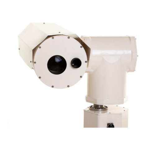
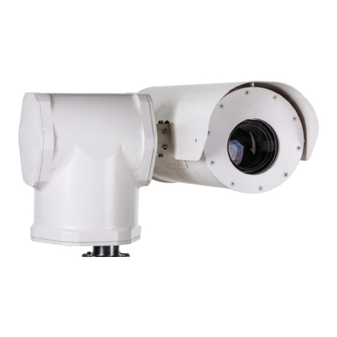
Evve Long Range MK Series User manual

Vlierberg 4-06A
3755 BS Eemnes
The Netherlands
Phone: +31 0 85 0441855 (NL)
Web : www.evvelongrange.com
MK-Series

Installation Manual MK-Series 2/10
ABOUT THIS DOCUMENT ........................................................................................................................... 3
ADDITIONAL INFORMATION & RELATED DOCUMENTS ......................................................................... 3
FFC COMPLIANCE ........................................................................................................................................ 2
SUPPORT SERVICES ..................................................................................................................................... 2
RETURNS....................................................................................................................................................... 2
SHIPMENT..................................................................................................................................................... 3
SAFETY INSTRUCTIONS ............................................................................................................................... 3
1. INTRODUCTION: EQUIPMENT SUPPLIED ............................................................................................. 5
2. INSTALLATION ......................................................................................................................................... 6
2.1 INSTALLATION OF THE POWER BOX............................................................................................... 6
2.2 INSTALLATION OF THE PT UNIT ...................................................................................................... 8
2.3 CONNECTION OF THE CAMERA TO THE PT UNIT.......................................................................... 9
EVVE LONG RANGETM

Installation Manual MK-Series 3/10
For information on the camera operation and configuration, please see
Operation Manual MK-2000HD. This manual is available from the Evve Long
Range website at: www.evvelongrange.com/downloads
This manual contains information on the operation and the different
interfaces of the following Evve Long RangeTM products:
2000HD Series - High Definition Camera System
The information in this manual is subject to change without notice. Please
refer to our website for the latest information.
NOTE: All graphics contained within this document, including screenshots and
other displays, are for reference use only and are subject to change.
Copyright 2020 by Evve Long Range B.V. (ELR). ELR has intellectual property rights to technology
embodied in the product described in this manual.
Evve Long RangeTM and Evve International BVTM are trademarkt of BOTHA BV.

Installation Manual MK-Series 2/10
This equipment has been tested and found to comply with the limits for a Class A digital device
pursuant to Part 15 of the FCC Rules. These limits are designed to provide reasonable protection
against harmful interference when the equipment is operated in a commercial environment. This
equipment generates, uses, and can radiate radio frequency energy, and, if not installed and used
in accordance with the instruction manual, may cause harmful interference to radio
communications. Operation of this equipment in a residential area is likely to cause harmful
interference, in which case the user will be required to correct the interference at his own expense.
This device complies with Part 15 of the FCC Rules. Operation is subject to the following two
conditions:
(1) this device may not cause harmful interference, and
(2) this device must accept any interference received, including interference that may cause
undesired operation. Changes or modifications to this device void the warranty.
High Definition Demonstration Camera Positioning System
This item was thoroughly tested and carefully packed at the factory prior to shipping. Upon
acceptance by the carrier, the carrier assumes responsibility for the item’s safe arrival. If you
receive the item in a damaged condition, apparent or concealed, a claim for damage must be made
to the carrier.
If a visual inspection shows damage upon receipt of this shipment, it must be noted on the freight
bill or express receipt and the notation signed by the carrier’s agent. Failure to do this can result
in the carrier refusing to honor the claim. When the damage is not apparent until the unit is
unpacked, a claim for concealed damage must be made.
Make a mail or phone request to the carrier for inspection immediately upon discovery of the
concealed damage. Keep all cartons and packing materials.
To return the product to the factory for service, please contact ELR for a Return Material
Authorization (RMA) Number.
Prominently display the RMA number on the outside of the shipping container(s) and on
paperwork contained inside. Give a brief description of why the equipment is being returned and
list the symptoms of any problems being experienced with the equipment.

Installation Manual MK-Series 3/10
Installation should be done only by qualified installers and conform to all local codes.
It is the users’ responsibility to ensure that the mounting methods are safe and adequate for
the location.
Use only A4 quality stainless steel hardware to fasten the mount to an outdoor surface.
All servicing should be performed by qualified service personnel. Procedures in this manual
do not require entry into the housing of the camera positioning system. The unit contains
potential high voltage. It also contains sensitive devices that can be damaged by static
discharge. To reduce the risk of electric shock and damage to the unit by static discharge do
not perform any servicing other that described in these instructions. If the unit is defective,
please contact the Customer Service Department for technical assistance.
Liability: It is the sole responsibility of the installer to provide proper installation in compliance
with all local codes and regulations.
WARNING:
Do not remove covers. There are no user-serviceable parts inside.
CAUTION:
Mount the camera system before the power is applied. After the power is applied the camera system
will start a configuration sequence and pan and tilt movement will occur. 17XXHD
WARNING:
Power supplies used with these cameras operate on 115 Vac or 230 Vac. These voltages are
dangerous. Use extreme care working with equipment connected to either 115 Vac or 230 Vac.
IMPORTANT!
If the camera needs to be shipped, please use the original packaging material which was designed
to protect the product during transportation. If the original packaging is lost or damaged, please
order a replacement at ELR.
SAFETY INSTRUCTIONS

Installation Manual MK-Series 4/10
The Evve Long Range products are part of the next generation of Long Range camera systems,
ranging from high-definition (HD) to standard-definition (SD) camera positioning systems. The
systems are IP (Internet Protocol) based with a full function built-in operating system. Operator
functions features are controlled from the On Screen Display (OSD).
A drive system positioned within the MK-2000 Series camera permits full 360° continuous pan and
90° tilt movements. The camera systems comply with MIL-STD-18F standards for temperature,
shock, and vibration specifications. For environmental protection the camera systems use an IP67
camera head enclosure and IP66 positioner enclosure.
At 50km the pixels per meter in
height will be 8. Assuming man is
2m approx. then 8 pixels is
Detection.
At 5km the pixels per meter in
height will be 40. Assuming man
is 2m approx. then 80 pixels is
Identification, i.e. it’s a man or
woman.
CLASS 3 (EYE & SPECULAR REFLECTION HAZARD):
Never aim the laser at a person’s eye or stare at the laser from within the beam.
Keep the beam path above or below eye level for one seated or standing.
Laser safety eyewear is needed if MPE (Maximum Permissible Exposure) is exceeded.
Don’t view beam directly with optical instruments unless a protective filter is used.
Only experienced and authorized individuals are permitted to operate the laser.
Secure the laser from operation by unauthorized personnel. A key switch should be used if
unauthorized personnel may gain access to the laser.
Always strive to enclose as much of the beam path as practical and to operate the laser in a
controlled access area.
During alignment, avoid placing one’s eye near the axis of the beam path, where specular
reflections are most likely to occur. Alignment eyewear should be considered.
Unnecessary specular (i.e., mirror-like) reflecting objects should be removed from the beam
path.
Mount the laser on a firm support to ensure the beam travels along its intended path.
Post laser hazard warning signs at entrances to laser use areas.
SAFETY INSTRUCTIONS

Installation Manual MK-Series 5/10
POWER BOX & CONNECTION CABLES
POWER BOX & CONNECTION CABLES
CAMERA HOUSING WITH SUNSHIELD
12 BOLTS (M12 STAINLESS STEEL) & ALLEN KEY SET

Installation Manual MK-Series 6/10
This chapter covers the general installation and cable requirements of the MK2000HD series.
2.1 INSTALLATION OF THE POWER BOX
1. Mount the powerbox at the correct position. (Tools
and materials for mounting are not included).
2. Connecting the red camera power cable:
2.1 Place the camera cable through the cable gland.
NOTE:
Before starting installation:
Choose a flat surface or bracket.
Have the bolts available.
Do NOT power the systems until all devices are connected.
CAUTION:
The bolts that are used to install the camera must be securely fastened.
After installation and before turning on the camera, check if the camera moves freely and has
enough clearance for pan and tilt movements without any obstructions.

Installation Manual MK-Series 7/10
2.2 Place a screwdriver flat in te opening of the socket.
2.3 Place the ground (yellow and green) cable in te
socket and remove the screwdriver.
2.4 Unscrew the screw at –V and +V.
2.5 Place the blue camera wire in -V.
2.6 Place the brown camera wire in +V.
3. Connecting the main power cable:
Place the main power cable through the cable
gland.
Place a screwdriver flat in the opening of the socket.
Place the ground (yellow and green) cable in the
yellow and GREEN socket and remove the
screwdriver.
Place the plus (brown) in the GREY socket and
remove the screwdriver.
Place the minus (blue) in the BLUE socket and
remove the screwdriver.
The power installation is ready. If you turn on the power, a green LED will light up.
The pwer cable is now ready to be connected to the connector of the PT unit.
2.1 INSTALLATION OF THE POWERBOX

Installation Manual MK-Series 8/10
2.2 INSTALLATION OF THE PT UNIT
1. Place the PT on a flat surface in the correct position
to mount the bolts.
2. Fasten the M12 bolts and check if the bolts are securely fastened.
3. Remove the connector (be carefull that you don’t damage the wire). Fasten the M12 bolts
and check if the bolts are securely fastened. Put the connector back in place.

Installation Manual MK-Series 9/10
2.3 CONNECTION OF THE CAMERA TO THE PT UNIT
1. Remove the bolts from the tilt axle.
2. Slide the camera housing on the drive shaft.
3. Secure the bolts on the drive shaft.
4. Connect the power and data cable from the
power box to the camera.
5. Turn on the power.

Installation Manual MK-Series 10/10
Vlierberg 4-06A
3755 BS Eemnes
The Netherlands
Phone: +31 0 85 0441855 (NL)
Web: www.evvelongrange.com
Other manuals for MK Series
1
This manual suits for next models
1
Table of contents
Other Evve Long Range Digital Camera manuals
