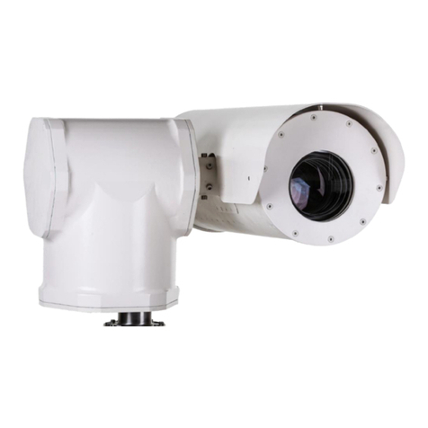
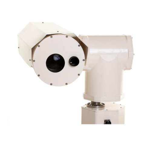
Evve Long Range MK Series User manual

Vlierberg 4-06A
3755 BS Eemnes
The Netherlands
Phone: +31 0 85 0441855 (NL)
Web : www.evvelongrange.com
MK-Series

Installation Manual MK-Series 2/24
ABOUT THIS DOCUMENT ........................................................................................................................... 3
ADDITIONAL INFORMATION & RELATED DOCUMENTS ......................................................................... 3
FFC COMPLIANCE ........................................................................................................................................ 2
SUPPORT SERVICES ..................................................................................................................................... 2
SAFETY INSTRUCTIONS ............................................................................................................................... 2
1. PROTOCOL ............................................................................................................................................... 5
2. VIDEOSTREAMS THROUGH CHARM 10CE............................................................................................ 5
2.1 CONNECTING TO THE CHARM ........................................................................................................ 5
2.2 OPERATING IN MULTICAST ............................................................................................................. 5
2.3 RTSP VIDEOSTREAM.......................................................................................................................... 6
2.4 UPDATING SOFTWARE...................................................................................................................... 6
2.5 ADJUSTING IP ADDRESS.................................................................................................................... 7
2.6 CONFIGURING THE CHARM ............................................................................................................. 8
2.7 NTP SERVER ADDRESS ...................................................................................................................... 9
3. PASSTRHOUGH PORT MOXA ............................................................................................................... 10
3.1 INSTALLING NPORT ADMINISTRATOR.......................................................................................... 10
3.2 SEARCHING FOR DEVICE SERVERS OVER A LAN .......................................................................... 10
3.3 ADJUSTING GENERAL SETTINGS.................................................................................................... 11
3.4 CONFIGURING SERIAL COMMUNICATION PARAMETERS .......................................................... 13
3.5 MAPPING COM PORT TO DEVICE .................................................................................................. 15
3.6 CONFIGURATION BY WEB CONSOLE ............................................................................................ 18
4. OPERATING THE CAMERA WITH KEY-BOARD KBD300A................................................................... 19
4.1 USE THE DIFFERENT SPEEDS.......................................................................................................... 19
4.2 SET OR CHANGE END STOPS ......................................................................................................... 20
4.3 ABSOLUTE CONTROLS.................................................................................................................... 20
5. CAMERA OPERATING COMMANDS ..................................................................................................... 21
5.1 CAMERA COMMANDS..................................................................................................................... 21
5.2 LENS COMMANDS........................................................................................................................... 22
6. LASER OPERATING COMMANDS ......................................................................................................... 23
EVVE LONG RANGETM

Installation Manual MK-Series 3/24
For information on the camera installation, please see Installation Manual
MK-Series. This manual is available from the Evve Long Range website at:
www.evvelongrange.com/downloads
ABOUT THIS DOCUMENT
ABOUT THIS DOCUMEN
This manual contains information on the operation and the different
interfaces of the following Evve Long RangeTM products:
2000HD - High Definition Camera System
The information in this manual is subject to change without notice. Please
refer to our website for the latest information.
NOTE: All graphics contained within this document, including screenshots and
other displays, are for reference use only and are subject to change.
Copyright 2020 by Evve Long Range B.V. (ELR). ELR has intellectual property rights to technology
embodied in the product described in this manual.
Evve Long RangeTM and Evve International BVTM are trademarkt of BOTHA BV.

Installation Manual MK-Series 2/24
This equipment has been tested and found to comply with the limits for a Class A digital device
pursuant to Part 15 of the FCC Rules. These limits are designed to provide reasonable protection
against harmful interference when the equipment is operated in a commercial environment. This
equipment generates, uses, and can radiate radio frequency energy, and, if not installed and used
in accordance with the instruction manual, may cause harmful interference to radio
communications. Operation of this equipment in a residential area is likely to cause harmful
interference, in which case the user will be required to correct the interference at his own expense.
This device complies with Part 15 of the FCC Rules. Operation is subject to the following two
conditions:
(1) this device may not cause harmful interference, and
(2) this device must accept any interference received, including interference that may cause
undesired operation. Changes or modifications to this device void the warranty.
High Definition Demonstration Camera Positioning System

Installation Manual MK-Series 3/24
1. Please read these instructions prior to use.
2. Please keep these instructions accessible.
3. Please heed all warnings.
4. Please follow all instructions.
5. Installation should be done only by qualified personnel and conform to all local
codes.
CAUTION: These servicing instructions are for use by qualified service personnel
only.
To reduce the risk of electric shock, do not perform any servicing other than that
contained in the operating instructions unless you are qualified to do so.
6. Use only mounting methods and materials capable of supporting at least four times the
combined weight of the pan-tilt unit, mounted payloads, and cabling.
7. For outdoor use, use only corrosion resistant hardware to fasten the mount and
payloads (e.g., stainless steel screws).
8. The unit should not be installed in environments that present conditions beyond
the environmental specification of pan-tilt unit. Installation near heat sources such
as radiators, heat registers, stoves, or other apparatus (including amplifiers) can
exceed the unit’s temperature ratings.
9. Refer all servicing to qualified service personnel. If the unit is damaged, remove power
immediately, and contact ELR.
10. A readily accessible power disconnect shall be incorporated into the installation wiring.
11. Only use replacement parts recommended by ELR.

Installation Manual MK-Series 4/24
Installation should be done only by qualified installers and conform to all local codes.
It is the users’ responsibility to ensure that the mounting methods are safe and adequate for
the location.
Use only stainless steel hardware to fasten the mount to an outdoor surface.
All servicing should be performed by qualified service personnel. Procedures in this manual
do not require entry into the housing of the camera positioning system. The unit contains
potential high voltage. It also contains sensitive devices that can be damaged by static
discharge. To reduce the risk of electric shock and damage to the unit by static discharge do
not perform any servicing other that described in these instructions. If the unit is defective,
please contact the Customer Service Department for technical assistance.
Liability: It is the sole responsibility of the installer to provide proper installation in compliance
with all local codes and regulations.
The Evve Long Range products are part of the next generation of Long Range camera systems,
ranging from high-definition (HD) to standard-definition (SD) camera positioning systems. The
systems are IP (Internet Protocol) based with a full function built-in operating system. Operator
functions features are controlled from the On Screen Display (OSD).
A drive system positioned within the MK-2000HD Series camera permits full 360° continuous pan
and 90° tilt movements. The camera systems comply with MIL-STD-18F standards for temperature,
shock, and vibration specifications. For environmental protection the camera systems use an IP67
camera head enclosure and IP66 positioner enclosure.
For more information on specifications and datasheets, please refer to specific product pages at Evve
Long Range website: www.evvelongrange.com/downloads.
At 50km the pixels per meter in
height will be 8. Assuming man is
2m approx. then 8 pixels is
Detection.
At 5km the pixels per meter in
height will be 40. Assuming man
is 2m approx. then 80 pixels is
Identification, i.e. it’s a man or
woman.
SAFETY INSTRUCTIONS
CLASS 3 (EYE & SPECULAR REFLECTION HAZARD):
Never aim the laser at a person’s eye or stare at the laser from within the beam.
Keep the beam path above or below eye level for one seated or standing.
Laser safety eyewear is needed if MPE (Maximum Permissible Exposure) is exceeded.
Don’t view beam directly with optical instruments unless a protective filter is used.
Only experienced and authorized individuals are permitted to operate the laser.
Secure the laser from operation by unauthorized personnel. A key switch should be used if
unauthorized personnel may gain access to the laser.
Always strive to enclose as much of the beam path as practical and to operate the laser in a
controlled access area.
During alignment, avoid placing one’s eye near the axis of the beam path, where specular
reflections are most likely to occur. Alignment eyewear should be considered.
Unnecessary specular (i.e., mirror-like) reflecting objects should be removed from the beam
path.
Mount the laser on a firm support to ensure the beam travels along its intended path.
Post laser hazard warning signs at entrances to laser use areas.

Installation Manual MK-Series 5/24
2.1 CONNECTING TO THE CHARM
You need a computer with Ethernet connection to the CHARM, and a web browser. Furthermore,
you need to know the IP address of the CHARM the default is 10.0.0.2.
Open the web browser and enter http://10.0.0.2 where 10.0.0.2 is the IP address of the CHARM.
The username is “v4” and the password “vision4ce”.
2.2 OPERATING IN MULTICAST
Looking at the start screen, towards the middle, you can see the option to ‘Edit’ the template.xml
file. Click the Edit button, and then follow the instructions in the file to:
Copy to another file.
Edit the copied file to:
oRemove the lower case x from the xStreamRTSPCfg0 entry.
oChange the bUseUnicast=”true” to bUseUnicast=”false”.
Save the file.
Ensure that the new file is ‘selected’ in the WebUpdater interface.
This MK-2000HD Series ELR camera has been adjusted to Pelco D 9600 Protocol.

Installation Manual MK-Series 6/24
2.3 RTSP VIDEOSTREAM
To obtain a direct RTSP VideoStream of the charm, use the following URL:
10.0.0.2:8001/charmstream
in which 10.0.0.2 is the IP address of the CHARM10CE.
To get a VideoStream in RTSP, you can a media player like for example VLC.
2.4 UPDATING SOFTWARE
The following instrucitons are for updating the tracker software on a CHARM with Ethernet
connection. Operating system and tracker sofware update over serial connection are not covered
here.
PRE-REQUISITES
You will need a computer with Ethernet connection to the CHARM, an update file and a web
browser. You will need to know the IP address of the CHARM (the default is 10.0.0.2).
PERFORMING AN UPDATE
Choose “Update
CHARM” from
the CHARM Main
Page then click
on the “Choose
file” button and
navigate to the
update file.
Once it has finished uploading you will see
“Processing update …” for a few seconds then
“Running update” and finally the installer output in
the box below or a “connection lost” message
when the CHARM reboots itself after installation.
2. VIDEOSTREAMS THROUGH CHARM 10CE

Installation Manual MK-Series 7/24
2.5 ADJUSTING IP ADDRESS
To change the IP address click on the “Change IP address link” from the CHARM Main Page. Enter
the new IP address and subnet mask. For IP addresses in the 10.0.0.x range the subnet mask
should be 255.0.0.0 and for IP addresses in the 192.168.1.x range the subnet mask should be
255.255.255.0.
You can optionally add a gateway address if you need the CHARM to connect to the internet, to
get internet (NTP) time for instance.
Upon pressing the submit / Set IP button the IP address will be changed and the CHARM rebooted.
To view the CHARM Web Updater again you will need to log in again at the new IP address.
2. VIDEOSTREAMS THROUGH CHARM 10CE

Installation Manual MK-Series 8/24
2.6 CONFIGURING THE CHARM
If you have been provided with additional configuration files by Vision4ce you can select which
one is loaded by the CHARM software.
Select the required configuration file and press the submit / “Set config” button. If the CHARM has
secondary user config files you can also select these. The selected files will be used next time the
CHARM is rebooted. There is a reboot button on the home page.
2. VIDEOSTREAMS THROUGH CHARM 10CE

Installation Manual MK-Series 9/24
2.7 NTP SERVER ADDRESS
If you need the time and date on your CHARM you can set up an NTP server.
Enter the server address and press “Set Address”. After the CHARM boots it can take around 3
minutes for the time to synchronise.
If you wish to use an NTP server on the internet you will need to set the gateway address in the IP
address page.
2. VIDEOSTREAMS THROUGH CHARM 10CE

Installation Manual MK-Series 10/24
3.1 INSTALLING NPORT ADMINISTRATOR
Locate
and
run
the
setup
program
on
the
NPort
Document
&
Software
CD.
Look
for
a
file
named
Npadm_Setup_[Version]_Build_[DateTime].exe
(e.g.,
“Npadm_Setup_Ver1.8_
Build_07041316.exe”).
You
may
also
download
the
latest
version
of
NPort
Administrator
from
Moxa’s
website
at:
http://www.moxa.com/support/download.aspx?d_id=1317
Run
NPort
Administrator
when
the
installation
is
complete.
3.2 SEARCHING FOR DEVICE SERVERS OVER A LAN
The Broadcast Search function is used to locate all NPort 5400 device servers that are connected
to the same LAN as your computer. Since the Broadcast Search function searches by MAC
address and not IP address, all NPorts connected to the LAN will be located, regardless of whether
or not they are part of the same subnet as the host.
In NPort Administrator, click Search to search your LAN for NPort device servers. When your unit
appears in the search results, you may click Stop to end the search. You may also wait a few more
moments for the search to complete.

Installation Manual MK-Series 11/24
The Configuration screen will list the NPort device servers that were found on the LAN. If your
unit cannot be found, you may have a network problem. Check all cables and verify that your PC
and device server are on the same LAN. If you still have problems, try connecting the device server
directly to your PC.
Before configuration the Nport, you will need to unlock the Nport first. Right-click the unit in the
configuration screen and select Unlock in the pop-up menu.
The default login is:
Username: admin
Password: moxa
3.3 ADJUSTING GENERAL SETTINGS
Right-click your unit in the Configuration screen and select Configure in the pop-up menu. If your
device server is password protected (the default password is moxa), first select Unlock in the pop-
up menu, and then click the Network tab in the configuration window. Select the Modify checkbox
for items you would like to modify. The device server must be assigned a unique IP address that
is valid for your network. Both fixed and dynamic IP addresses are supported. Consult with your
network administrator if you are not sure how to set these parameters.
When you are ready to restart the device server with the new settings, click OK.
3. PASSTRHOUGH PORT MOXA

Installation Manual MK-Series 12/24
STATIC IP ADDRESSES
For most applications, you will assign a fixed IP address to the device server. To assign a static
(fixed) IP address, the IP Configuration parameter must be set to Static, which is the default
setting. You may then modify the IP Address and Netmask parameters.
The operation mode parameters for each device port can be configured through NPort
Administrator. Open your device server’s configuration window using the same method you used
to adjust the network parameters. On the Operating Mode screen, select the Modify check box
and then select the device port that you wish to configure. Click Settings to configure the selected
device port.
Set the operating mode and associated parameters as needed. Refer to:
https://www.moxa.com/Moxa/media/PDIM/S100000213/moxa-nport-ia5000-series-manual-
v4.0.pdf for additional information on operating modes and advanced settings.
When you are ready to restart the device server with the new settings, click OK.
OPERATION MODE SELECTION CHART
3. PASSTRHOUGH PORT MOXA

Installation Manual MK-Series 13/24
3.4 CONFIGURING SERIAL COMMUNICATION PARAMETERS
This section covers the configuration of each device port’s serial communication parameters:
baudrate, stop bit, etc.
SERIAL PARAMETER REVIEW
The following parameters need to be set correctly on the device port to ensure proper commu-
nication with your device. Refer to your device’s documentation for the appropriate settings.
PARAMETER
SETTING
FACTORY
DEFAULT
DESCRIPTION
NECES-
SITY
Baudrate
Support standard
baudrates (bps):
50/ 75/ 110/ 134/
150/ 300/ 600/
1200 1800/
2400/ 4800/
7200/ 9600/
19200/ 38400/
57600/ 115200/
230.4k/ 460.8k/
921.6k
* The NPort
5210/5230/5232I
Series, and IA
5000 Series are
up to 230.4 kbps
115200 bps
The data transmission rate to and
from the attached serial device.
Need to
9600
Data bits
5, 6, 7, 8
8
The size of each data character.
8
Stop bits
1, 1.5, 2
1
The size of the stop character.
1
Parity
None, Even, Odd,
Space, Mark
None
The parity that will be used. Even and
Odd parity provide rudimentary error-
checking; Space and Mark parity are
rarely used.
None
Flow control
None, RTS/CTS,
DTR/DSR,
Xon/Xoff
RTS/CTS
The method used to suspend and
resume data transmission to ensure
that data is not lost. RTS/CTS (hard-
ware) flow control is recommended.
Required
FIFO
Enable, Disable
Enable
Controls whether the device port’s buil-
In 128-byte FIFO buffer is used. When
enabled, the FIFO helps reduce data
loss regardless of direction.
Required
Interface
RS-232
RS-422
2-wire RS-485
4-wire RS-485
RS-232
The serial interface that will be used.
The options that are available depend
on the specific model of device server.
Set to
422
3. PASSTRHOUGH PORT MOXA

Installation Manual MK-Series 14/24
ADJUSTING SERIAL PARAMETERS
The serial communication parameters for each device port can be configured through NPort
Administrator. Open your device server’s configuration window, using the same method you used
to configure network parameters. On the Serial screen, select the Modify check box and then
select the device port that you wish to configure. Click Settings to configure the selected device
port.
Modify the parameters as needed. When you are ready to restart the device server with the new
settings, click OK.
3. PASSTRHOUGH PORT MOXA

Installation Manual MK-Series 15/24
3.5 MAPPING COM PORT TO DEVICE
Only required when operation mode is set to Real COM or RFC2217)
This section covers how to map the COM ports on a Windows PC to NPort device ports. The
mapping will allow Windows software to access serial devices over the network as if they were
local COM devices, providing instant device networking without software migration. COM mapping
is supported in Real COM and RFC2217 modes only.
The following instructions are for device ports operating in Real COM mode. For device ports
operating in RFC2217 mode, follow the instructions for your particular driver. Real COM mode also
supports TTY port mapping on Linux and UNIX systems.
SPECIFYING THE TARGET DEVICE SERVER
In NPort Administrator, click COM Mapping in the Function panel to open the COM Mapping
window. Right-click on an empty line in the COM Mapping window. Select Add Target in the pop-
up menu to assign your device server as the mapping target.
A list of NPort device servers that have been found by NPort Administrator will appear. Select your
device server and click Finish.
3. PASSTRHOUGH PORT MOXA

Installation Manual MK-Series 16/24
ASSIGNING COM PORT NUMBER TO DEVICE PORT
The COM Mapping screen shows a list of available device ports on the network. Right-click the
target device port and select COM Settings in the pop-up menu.
On the Basic Settings screen, select the COM
port number that will be mapped to the device
port. You can map multiple COM ports at the
same time by selecting the Auto Enumerating
check box to number the COM ports
automatically.
On the Serial Parameters screen, adjust the
settings to match your device. These settings,
which are only used for serial printers, must
also match the settings on the device port. Click
OK when you are satisfied with your changes.
3. PASSTRHOUGH PORT MOXA

Installation Manual MK-Series 17/24
ADVANCED SETTINGS
(See https://www.moxa.com/Moxa/media/PDIM/S100000213/moxa-nport-ia5000-series-manual-
v4.0.pdf for detailed information about NPort Administrator’s Advanced Settings.)
Tx Mode: In Hi-Performance mode, the driver immediately issues a “Tx Empty” response to
the program after sending data to the NPort. In Classical mode, the driver sends the “Tx
Empty” response after confirmation is received from the NPort. Classical mode is
recommended if you want to ensure that all data is sent out before further processing.
FIFO: Tells the driver whether or not to use FIFO transmission.
Network Timeout: Specifies when an open, close, or serial parameter change operation will
time out.
Fast Flush: When enabled, the driver flushes only the local buffer on the host for a Win32
PurgeComm() function call. When disabled, both the local and remote buffers are flushed. If
your application uses PurgeComm() and it performance seems sluggish, try enabling Fast
Flush.
Always Accept Open Requests: Even if the driver cannot establish a connection with the
NPort, the user's software will still be able to open the mapped COM port, the same as with
an onboard COM port.
Ignore TX Purge: The application can use Win32 API PurgeComm to clear the output buffer
and terminate outstanding overlapped write operations. Select Ignore TX Purge if you do not
want the output buffer to be purged.
APPLY CHANGE
Right-click COM Mapping in the Function panel. Select Apply Change in the pop-up menu to save
the current COM mapping settings. Your application will now be able to access the target serial
device using the COM port.
3. PASSTRHOUGH PORT MOXA

Installation Manual MK-Series 18/24
3.6 CONFIGURATION BY WEB CONSOLE
The Web Console is the most user-friendly way to configure NPort products. In this section, we
cover a device server’s general settings.
OPENING YOUR BROWSER
1. Open your browser with the cookie functionality enabled. (To enable your browser for
cookies, right-click on your desktop’s Internet Explorer icon, select Properties, click on the
Security tab, and then select the three Enable options as shown in the figure below.)
2. Type 192.168.127.254 in the Address input box (use the correct IP address if different from
the default), and then press Enter.
3. You will be prompted to enter the password to access the NPort web console. (The default
password for NPort is moxa.)
3. PASSTRHOUGH PORT MOXA
Other manuals for MK Series
1
This manual suits for next models
1
Table of contents
Other Evve Long Range Digital Camera manuals
Popular Digital Camera manuals by other brands
Ikegami
Ikegami ICD-48E instruction manual

Pentax
Pentax Optio E50 - Optio E50 - 8.1MP Digital Camera operating manual
Nikon
Nikon D80 VBA14001 Repair manual
Olympus
Olympus 1030SW - Stylus Digital Camera instruction manual
Cubert
Cubert S185 Hardware operation guide

Olympus
Olympus STYLUS-550WP instruction manual
