EWM Trolly 35.2-2 User manual

Operating instructions
EN
Transport systems
Trolly 35.2-2
099-008296-EW501
Observe additional system documents!
23.02.2021

General instructions
WARNING
Read the operating instructions!
The operating instructions provide an introduction to the safe use of the products.
•Read and observe the operating instructions for all system components, especially the sa-
fety instructions and warning notices!
•Observe the accident prevention regulations and any regional regulations!
•The operating instructions must be kept at the location where the machine is operated.
•Safety and warning labels on the machine indicate any possible risks.
Keep these labels clean and legible at all times.
•The machine has been constructed to state-of-the-art standards in line with any applicable
regulations and industrial standards. Only trained personnel may operate, service and re-
pair the machine.
•Technical changes due to further development in machine technology may lead to a dif-
fering welding behaviour.
In the event of queries on installation, commissioning, operation or special conditions at the
installation site, or on usage, please contact your sales partner or our customer service
department on +49 2680 181-0.
A list of authorised sales partners can be found at www.ewm-group.com/en/specialist-dealers.
Liability relating to the operation of this equipment is restricted solely to the function of the equipment. No
other form of liability, regardless of type, shall be accepted. This exclusion of liability shall be deemed ac-
cepted by the user on commissioning the equipment.
The manufacturer is unable to monitor whether or not these instructions or the conditions and methods
are observed during installation, operation, usage and maintenance of the equipment.
An incorrectly performed installation can result in material damage and injure persons as a result. For this
reason, we do not accept any responsibility or liability for losses, damages or costs arising from incorrect
installation, improper operation or incorrect usage and maintenance or any actions connected to this in
any way.
© EWM AG
Dr. Günter-Henle-Strasse 8
56271 Mündersbach Germany
Tel.: +49 2680 181-0, Fax: -244
Email: info@ewm-group.com
www.ewm-group.com
The copyright to this document remains the property of the manufacturer.
Copying, including extracts, only permitted with written approval.
The content of this document has been prepared and reviewed with all reasonable care. The information
provided is subject to change; errors excepted.

Contents
Notes on using these operating instructions
099-008296-EW501
23.02.2021
3
1 Contents
1Contents.......................................................................................................................................... 3
2For your safety ............................................................................................................................... 4
2.1 Notes on using these operating instructions.......................................................................... 4
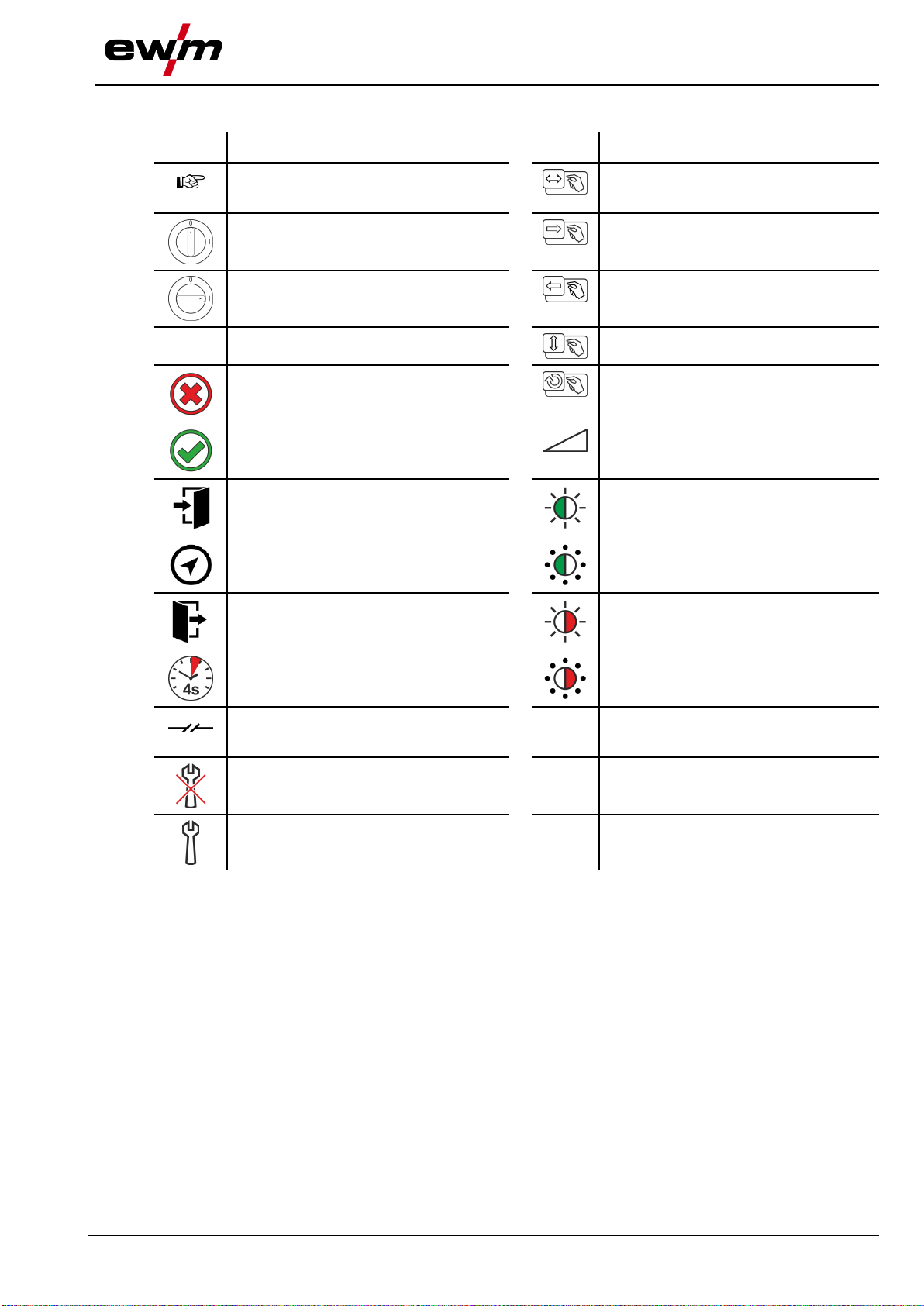
2.2 Explanation of icons............................................................................................................... 5
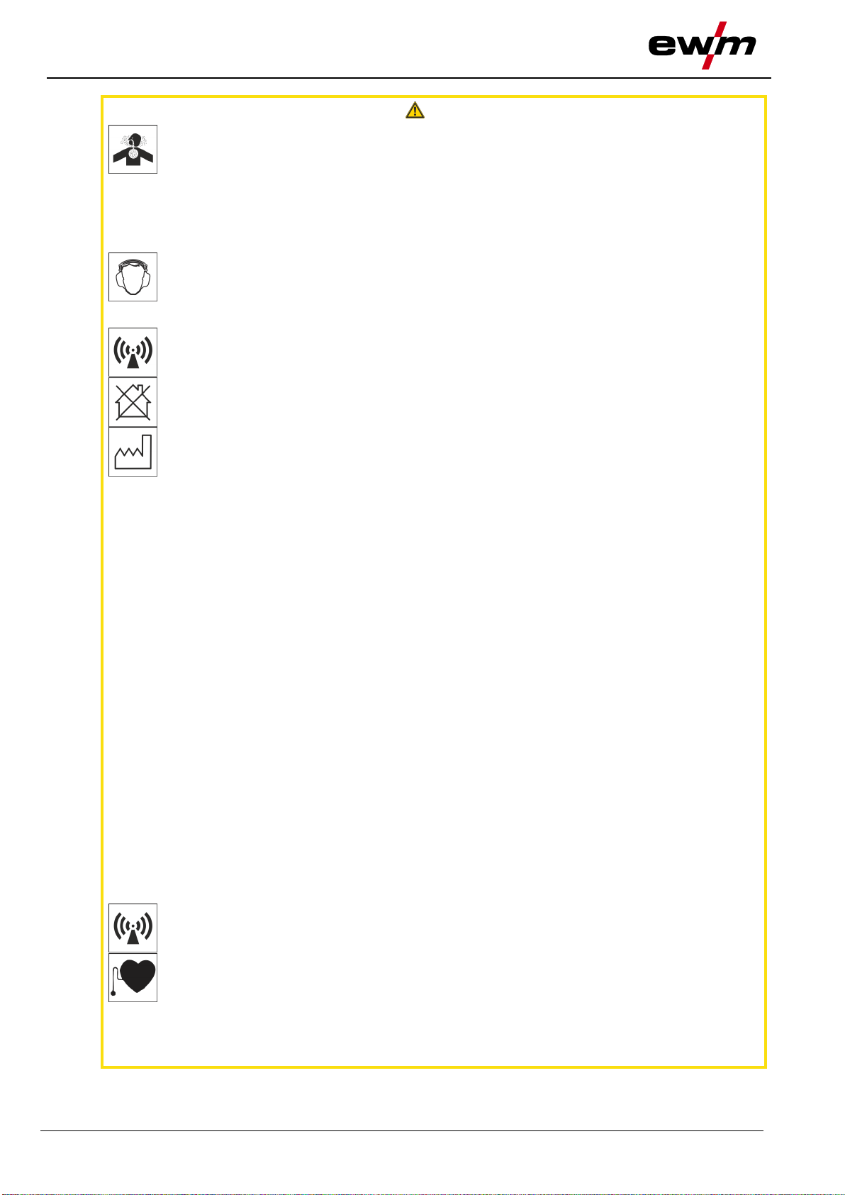
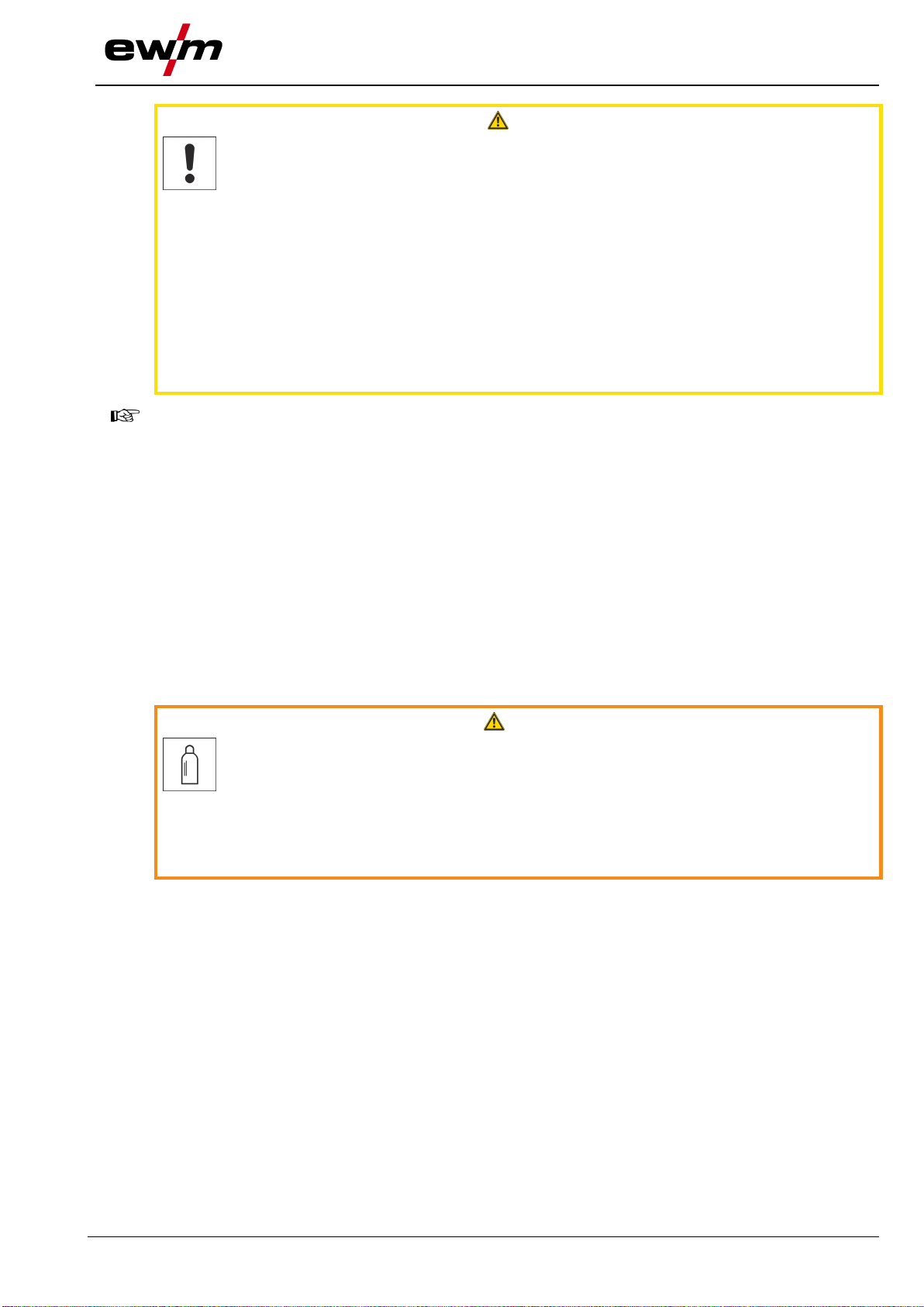
2.3 Safety instructions..................................................................................................................6
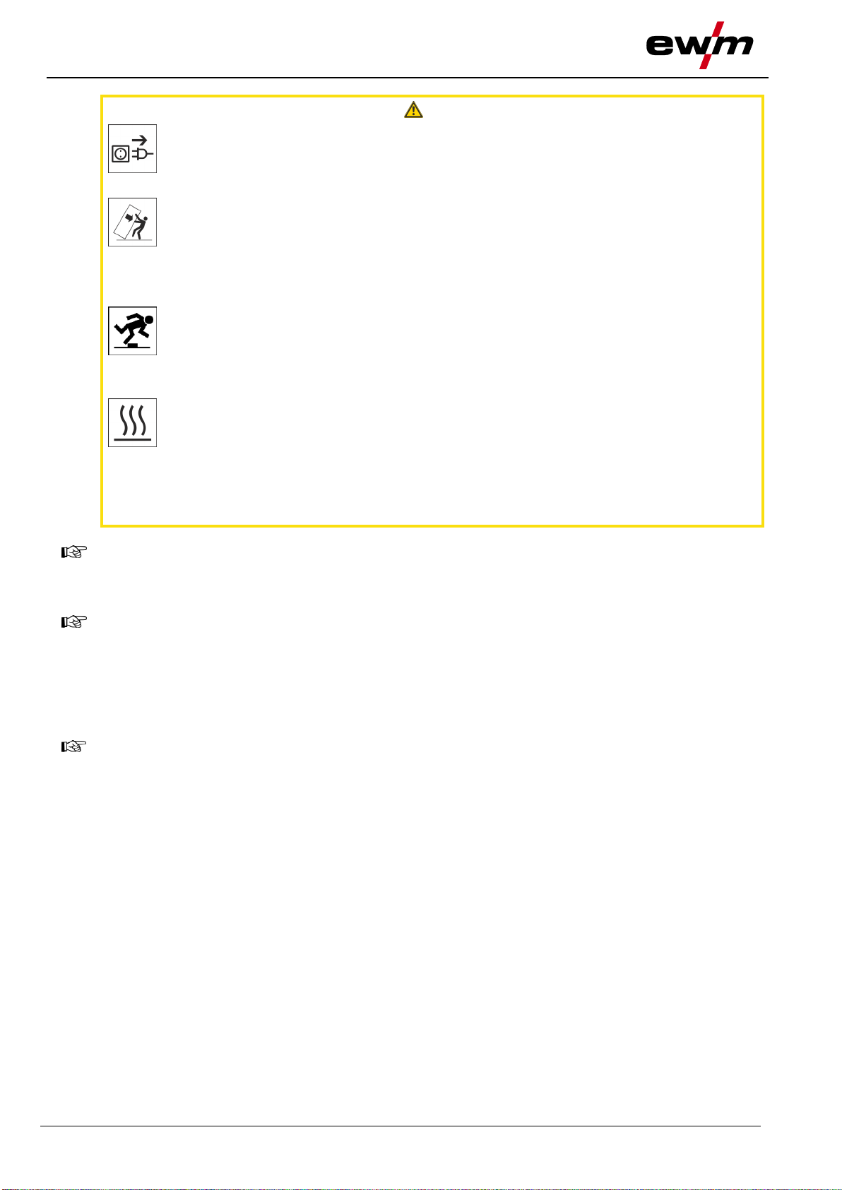
2.4 Transport and installation ......................................................................................................9
3Intended use.................................................................................................................................11
3.1 Applications..........................................................................................................................11
3.2 Use and operation solely with the following machines........................................................11
3.3 Documents which also apply ...............................................................................................11
3.3.1 Warranty...............................................................................................................11
3.3.2 Service documents (spare parts) .........................................................................11
3.3.3 Part of the complete documentation.....................................................................12
4Machine description –quick overview ......................................................................................13
4.1 Front view / rear view...........................................................................................................13
5Design and function..................................................................................................................... 14
5.1 Assembly .............................................................................................................................14
5.1.1 Install the machine feet adapter ...........................................................................15
5.2 Mounting the machine..........................................................................................................16
5.2.1 Fixing the welding machine..................................................................................16
5.2.2 Fixing a welding machine with cooling module ....................................................18
5.2.3 Securing the shielding gas cylinder......................................................................19
5.3 Using the transport system..................................................................................................20
5.3.1 Transport ..............................................................................................................20
5.3.2 Cable or hose holders ..........................................................................................21
6Maintenance, care and disposal.................................................................................................22
6.1 Maintenance work, intervals ................................................................................................22
6.1.1 Daily maintenance tasks.......................................................................................22
6.1.2 Monthly maintenance tasks..................................................................................22
6.2 Disposing of equipment .......................................................................................................22
7Technical data .............................................................................................................................. 23
7.1 Trolly 35.2-2.........................................................................................................................23
8Accessories.................................................................................................................................. 24
8.1 General accessories............................................................................................................24
9Appendix.......................................................................................................................................25
9.1 Searching for a dealer..........................................................................................................25

For your safety
Notes on using these operating instructions
4
099-008296-EW501
23.02.2021
2 For your safety
2.1 Notes on using these operating instructions
DANGER
Working or operating procedures which must be closely observed to prevent imminent
serious and even fatal injuries.
•Safety notes include the "DANGER" keyword in the heading with a general warning symbol.
•The hazard is also highlighted using a symbol on the edge of the page.
WARNING
Working or operating procedures which must be closely observed to prevent serious
and even fatal injuries.
•Safety notes include the "WARNING" keyword in the heading with a general warning sym-
bol.
•The hazard is also highlighted using a symbol in the page margin.
CAUTION
Working or operating procedures which must be closely observed to prevent possible
minor personal injury.
•The safety information includes the "CAUTION" keyword in its heading with a general warn-
ing symbol.
•The risk is explained using a symbol on the edge of the page.
Technical aspects which the user must observe to avoid material or equipment damage.
Instructions and lists detailing step-by-step actions for given situations can be recognised via bullet
points, e.g.:
•Insert the welding current lead socket into the relevant socket and lock.

For your safety
Explanation of icons
099-008296-EW501
23.02.2021
5
2.2 Explanation of icons
Symbol
Description
Symbol
Description
Indicates technical aspects which the u-
ser must observe.
Activate and release / Tap / Tip
Switch off machine
Release
Switch on machine
Press and hold
Switch
Incorrect / Invalid
Turn
Correct / Valid
Numerical value –adjustable
Input
Signal light lights up in green
Navigation
Signal light flashes green
Output
Signal light lights up in red
Time representation (e.g.: wait 4 s / ac-
tuate)
Signal light flashes red
Interruption in the menu display (other
setting options possible)
Tool not required/do not use
Tool required/use

For your safety
Safety instructions
6
099-008296-EW501
23.02.2021
2.3 Safety instructions
WARNING
Risk of accidents due to non-compliance with the safety instructions!
Non-compliance with the safety instructions can be fatal!
•Carefully read the safety instructions in this manual!
•Observe the accident prevention regulations and any regional regulations!
•Inform persons in the working area that they must comply with the regulations!
Risk of injury from electrical voltage!
Voltages can cause potentially fatal electric shocks and burns on contact. Even low vol-
tages can cause a shock and lead to accidents.
•Never touch live components such as welding current sockets or stick, tungsten or wire
electrodes!
•Always place torches and electrode holders on an insulated surface!
•Wear the full personal protective equipment (depending on the application)!
•The machine may only be opened by qualified personnel!
•The device must not be used to defrost pipes!
Hazard when interconnecting multiple power sources!
If a number of power sources are to be connected in parallel or in series, only a techni-
cal specialist may interconnect the sources as per standard IEC 60974-9:2010: Installa-
tion and use and German Accident Prevention Regulation BVG D1 (formerly VBG 15) or
country-specific regulations.
Before commencing arc welding, a test must verify that the equipment cannot exceed
the maximum permitted open circuit voltage.
•Only qualified personnel may connect the machine.
•When taking individual power sources out of operation, all mains and welding current leads
must be safely disconnected from the welding system as a whole. (Hazard due to reverse
polarity voltage!)
•Do not interconnect welding machines with pole reversing switch (PWS series) or machines
for AC welding since a minor error in operation can cause the welding voltages to be com-
bined, which is not permitted.
Risk of injury due to radiation or heat!
Arc radiation can lead to skin and eye injuries.
Contact with hot workpieces and sparks can lead to burns.
•Use hand shield or welding helmet with the appropriate safety level (depends on the appli-
cation).
•Wear dry protective clothing (e.g. hand shield, gloves, etc.) in accordance with
the applicable regulations of your country.
•Persons who are not directly involved should be protected with a welding curtain or suitable
safety screen against radiation and the risk of blinding!

For your safety
Safety instructions
099-008296-EW501
23.02.2021
7
WARNING
Risk of injury due to improper clothing!
During arc welding, radiation, heat and voltage are sources of risk that cannot be
avoided. The user has to be equipped with the complete personal protective equipment
at all times. The protective equipment has to include:
•Respiratory protection against hazardous substances and mixtures (fumes and vapours);
otherwise implement suitable measures such as extraction facilities.
•Welding helmet with proper protection against ionizing radiation (IR and UV radiation) and
heat.
•Dry welding clothing (shoes, gloves and body protection) to protect against warm environ-
ments with conditions comparable to ambient temperatures of 100 °C or higher and arcing
and work on live components.
•Hearing protection against harming noise.
Explosion risk!
Apparently harmless substances in closed containers may generate excessive pressure
when heated.
•Move containers with inflammable or explosive liquids away from the working area!
•Never heat explosive liquids, dusts or gases by welding or cutting!
Fire hazard!
Due to the high temperatures, sparks, glowing parts and hot slag that occur during
welding, there is a risk of flames.
•Be watchful of potential sources of fire in the working area!
•Do not carry any easily inflammable objects, e.g. matches or lighters.
•Ensure suitable fire extinguishers are available in the working area!
•Thoroughly remove any residue of flammable materials from the workpiece prior to starting
to weld.
•Only further process workpieces after they have cooled down. Do not allow them to contact
any flammable materials!

For your safety
Safety instructions
8
099-008296-EW501
23.02.2021
CAUTION
Smoke and gases!
Smoke and gases can lead to breathing difficulties and poisoning. In addition, solvent
vapour (chlorinated hydrocarbon) may be converted into poisonous phosgene due to
the ultraviolet radiation of the arc!
•Ensure that there is sufficient fresh air!
•Keep solvent vapour away from the arc beam field!
•Wear suitable breathing apparatus if appropriate!
Noise exposure!
Noise exceeding 70 dBA can cause permanent hearing damage!
•Wear suitable ear protection!
•Persons located within the working area must wear suitable ear protection!
According to IEC 60974-10, welding machines are divided into two classes of
electromagnetic compatibility (the EMC class can be found in the Technical
data) > see 7 chapter:
Class A machines are not intended for use in residential areas where the power supply comes
from the low-voltage public mains network. When ensuring the electromagnetic compatibility of
class A machines, difficulties can arise in these areas due to interference not only in the supply
lines but also in the form of radiated interference.
Class B machines fulfil the EMC requirements in industrial as well as residential areas, inclu-
ding residential areas connected to the low-voltage public mains network.
Setting up and operating
When operating arc welding systems, in some cases, electro-magnetic interference can occur
although all of the welding machines comply with the emission limits specified in the standard.
The user is responsible for any interference caused by welding.
In order to evaluate any possible problems with electromagnetic compatibility in the
surrounding area, the user must consider the following: (see also EN 60974-10 Appendix A)
•Mains, control, signal and telecommunication lines
•Radios and televisions
•Computers and other control systems
•Safety equipment
•The health of neighbouring persons, especially if they have a pacemaker or wear a hearing
aid
•Calibration and measuring equipment
•The immunity to interference of other equipment in the surrounding area
•The time of day at which the welding work must be carried out
Recommendations for reducing interference emission
•Mains connection, e.g. additional mains filter or shielding with a metal tube
•Maintenance of the arc welding system
•Welding leads should be as short as possible and run closely together along the ground
•Potential equalization
•Earthing of the workpiece. In cases where it is not possible to earth the workpiece directly,
it should be connected by means of suitable capacitors.
•Shielding from other equipment in the surrounding area or the entire welding system
Electromagnetic fields!
The power source may cause electrical or electromagnetic fields to be produced which
could affect the correct functioning of electronic equipment such as IT or CNC devices,
telecommunication lines, power cables, signal lines and pacemakers.
•Observe the maintenance instructions > see 6 chapter!
•Unwind welding leads completely!
•Shield devices or equipment sensitive to radiation accordingly!
•The correct functioning of pacemakers may be affected (obtain advice from a doctor if nec-
essary).

For your safety
Transport and installation
099-008296-EW501
23.02.2021
9
CAUTION
Obligations of the operator!
The respective national directives and laws must be complied with when operating the
machine!
•Implementation of national legislation relating to framework directive 89/391/EEC on the int-
roduction of measures to encourage improvements in the safety and health of workers at
work and associated individual guidelines.
•In particular, directive 89/655/EEC concerning the minimum safety and health requirements
for the use of work equipment by workers at work.
•The regulations applicable to occupational safety and accident prevention in the country
concerned.
•Setting up and operating the machine as per IEC 60974.-9.
•Brief the user on safety-conscious work practices on a regular basis.
•Regularly inspect the machine as per IEC 60974.-4.
The manufacturer's warranty becomes void if non-genuine parts are used!
•Only use system components and options (power sources, welding torches, electrode hold-
ers, remote controls, spare parts and replacement parts, etc.) from our range of products!
•Only insert and lock accessory components into the relevant connection socket when the ma-
chine is switched off.
Requirements for connection to the public mains network
High-performance machines can influence the mains quality by taking current from the mains
network. For some types of machines, connection restrictions or requirements relating to the
maximum possible line impedance or the necessary minimum supply capacity at the interface
with the public network (Point of Common Coupling, PCC) can therefore apply. In this respect,
attention is also drawn to the machines' technical data. In this case, it is the responsibility of the
operator, where necessary in consultation with the mains network operator, to ensure that the
machine can be connected.
2.4 Transport and installation
WARNING
Risk of injury due to improper handling of shielding gas cylinders!
Improper handling and insufficient securing of shielding gas cylinders can cause seri-
ous injuries!
•Observe the instructions from the gas manufacturer and any relevant regulations concern-
ing the use of compressed air!
•Do not attach any element to the shielding gas cylinder valve!
•Prevent the shielding gas cylinder from heating up.

For your safety
Transport and installation
10
099-008296-EW501
23.02.2021
CAUTION
Risk of accidents due to supply lines!
During transport, attached supply lines (mains leads, control cables, etc.) can cause
risks, e.g. by causing connected machines to tip over and injure persons!
•Disconnect all supply lines before transport!
Risk of tipping!
There is a risk of the machine tipping over and injuring persons or being damaged itself
during movement and set up. Tilt resistance is guaranteed up to an angle of 10° (ac-
cording to IEC 60974-1).
•Set up and transport the machine on level, solid ground.
•Secure add-on parts using suitable equipment.
Risk of accidents due to incorrectly installed leads!
Incorrectly installed leads (mains, control and welding leads or intermediate hose pack-
ages ) can present a tripping hazard.
•Lay the supply lines flat on the floor (avoid loops).
•Avoid laying the leads on passage ways.
Risk of injury from heated coolant and its connections!
The coolant used and its connection or connection points can heat up significantly
during operation (water-cooled version). When opening the coolant circuit, escaping
coolant may cause scalding.
•Open the coolant circuit only when the power source or cooling unit is switched off!
•Wear proper protective equipment (protective gloves)!
•Seal open connections of the hose leads with suitable plugs.
The units are designed for operation in an upright position!
Operation in non-permissible positions can cause equipment damage.
•Only transport and operate in an upright position!
Accessory components and the power source itself can be damaged by incorrect connection!
•Only insert and lock accessory components into the relevant connection socket when the
machine is switched off.
•Comprehensive descriptions can be found in the operating instructions for the relevant ac-
cessory components.
•Accessory components are detected automatically after the power source is switched on.
Protective dust caps protect the connection sockets and therefore the machine against dirt and
damage.
•The protective dust cap must be fitted if there is no accessory component being operated on
that connection.
•The cap must be replaced if faulty or if lost!

Intended use
Applications
099-008296-EW501
23.02.2021
11
3 Intended use
WARNING
Hazards due to improper usage!
The machine has been constructed to the state of the art and any regulations and stand-
ards applicable for use in industry and trade. It may only be used for the welding proce-
dures indicated at the rating plate. Hazards may arise for persons, animals and material
objects if the equipment is not used correctly. No liability is accepted for any damages
arising from improper usage!
•The equipment must only be used in line with its designated purpose and by trained or
expert personnel!
•Do not improperly modify or convert the equipment!
3.1 Applications
For transporting arc welding systems and process-dependent components such as torch cooling modules
or shielding gas cylinders.
3.2 Use and operation solely with the following machines
In general, the trolley accommodates machines with with round or rectangular feet. For machines with
rectangular feet, the machine feet adapter (included) has to be installed on the trolley.
The following table shows system component combination options:
cool35 U31
cool40 U31
cool41 U31
cool50 U40
Tetrix 230 TM
Tetrix 300
Tetrix 300-2 TM /
Tetrix 300 puls TM
Tetrix 400-2 TM
Picomig 180 / 185 / 305 TKG
Taurus / Phoenix 355 TKM
possible
not possible
3.3 Documents which also apply
3.3.1 Warranty
For information on warranty, maintenance and testing, see the website www.ewm-group.com.
3.3.2 Service documents (spare parts)
WARNING
Do not carry out any unauthorised repairs or modifications!
To avoid injury and equipment damage, the unit must only be repaired or modified by
specialist, skilled persons!
The warranty becomes null and void in the event of unauthorised interference.
•Appoint only skilled persons for repair work (trained service personnel)!
Spare parts can be obtained from the relevant authorised dealer.

Intended use
Documents which also apply
12
099-008296-EW501
23.02.2021
3.3.3 Part of the complete documentation
This document is part of the complete documentation and valid only in combination with all other
parts of these instructions! Read and observe the operating instructions for all system
components, especially the safety instructions!
The illustration shows a general example of a welding system.
Figure 3-1
Item
Documentation
A.1
Options conversion instructions
A.2
Power source
A.3
Cooling unit, voltage converter, tool box etc.
A.4
Transport cart
A.5
Welding torch
A.6
Remote control
A.7
Control
A
Complete documentation

Machine description –quick overview
Front view / rear view
099-008296-EW501
23.02.2021
13
4 Machine description – quick overview
4.1 Front view / rear view
Figure 4-1
Item
Symbol
Description 0
1
Carrying handle
2
Cable or hose holders (arranged opposite)
3
Machine hold-down device > see 5.2 chapter
4
Machine feet adapter > see 5.1.1 chapter
5
Transport wheel
6
Foot bar > see 5.3 chapter
7
Shielding gas cylinder holder
8
Securing element
Clamping belt for attaching the shielding gas cylinder
9
Holder for shielding gas cylinder

Design and function
Assembly
14
099-008296-EW501
23.02.2021
5 Design and function
5.1 Assembly
Figure 5-1
Item
Symbol
Description 0
1
Cable or hose holders (arranged opposite)
2
Threaded grooved pin
M5 x 14 mm
•Fasten the holders to the transport cart using the screws supplied. The brackets must be attached in
opposite directions (see illustration).

Design and function
Assembly
099-008296-EW501
23.02.2021
15
5.1.1 Install the machine feet adapter
In general, the trolley accommodates machines with with round or rectangular feet. For machines with
rectangular feet, the machine feet adapter (included) has to be installed on the trolley.
CAUTION
Risk of accidents due to improperly prepared transport vehicle!
Depending on the machine series the trolley has to be adapted to
mount the machine. Failing to adapt the trolley can cause the ma-
chine being transported to topple and lead to injuries!
•Use trolley with machine feet adapter for machines with rectangular
feet.
•Remove machine feet adapter for machines with round feet.
Figure 5-2
Item
Symbol
Description 0
1
Machine feet adapter
2
Machine carrier plate
To support the welding machine.
3
Tallow-drop hexagon screw
M8x10
•Install the machine feet adapter on the machine support using an allen key (5 mm) and the supplied
screws,

Design and function
Mounting the machine
16
099-008296-EW501
23.02.2021
5.2 Mounting the machine
CAUTION
Improperly secured equipment!
Equipment, equipment combinations and accessories incorrectly fastened onto trans-
port systems can tip over during transport and cause injuries!
•Only used the original parts supplied to fasten the equipment.
•Use the systems only for transporting the machines > see 3.2 chapter.
•Check the fixing points before each transport and at regular intervals.
5.2.1 Fixing the welding machine
Mounting process using an example. Procedure is similar for other models as appropriate.
The position of the cross bar depends on the casing width.

Design and function
Mounting the machine
099-008296-EW501
23.02.2021
17
Figure 5-3
Item
Symbol
Description 0
1
Power source
2
Cross arm
Upper device attachment

Design and function
Mounting the machine
18
099-008296-EW501
23.02.2021
Item
Symbol
Description 0
3
Plain washer
M5
4
Star handle
M8x20
•Place the welding machine with its feet in the holes provided.
•Lower machine hold-down fitting onto the handle of the power source.
•Secure the machine hold-down fitting using star handles.
5.2.2 Fixing a welding machine with cooling module
The illustration serves as an example only.
Figure 5-4
Item
Symbol
Description 0
1
Cooling unit
2
Power source
3
Plain washer
M5
4
Star handle
M8x20
5
Cross arm
Upper device attachment
•Place the cooling unit with its feet in the recesses provided.
•Connect the welding machine with the cooling unit. (See operating instructions for cooling unit/power
source)
•Lower machine hold-down device to the handle of the power source.
•Secure the machine hold-down device using star knobs.

Design and function
Mounting the machine
099-008296-EW501
23.02.2021
19
5.2.3 Securing the shielding gas cylinder
WARNING
Risk of injury due to improper handling of shielding gas cylinders!
Improper handling and insufficient securing of shielding gas cylinders can cause seri-
ous injuries!
•The cylinders must be secured with at least two clamping belts.
•Adapt the fastening point of the upper clamping belt to the size of the cylinder.
•Do not attach anything to the shielding gas cylinder valve.
Figure 5-5
Item
Symbol
Description 0
1
Shielding gas cylinder
2
Upper fastening point of the clamping belt
3
Middle fastening point of the clamping belt
4
Securing element
Clamping belt for attaching the shielding gas cylinder
5
Shielding gas cylinder holder
•Adapting the height of the upper cylinder fastening:
large shielding gas cylinder > use the upper fastening point
small shielding gas cylinder > use the middle fastening point
•Open the tension closures on the clamping belts.
•Place the shielding gas cylinder in the holder provided.
•Secure the shielding gas cylinder with the clamping belts (ensure that they are firm and tight).

Design and function
Using the transport system
20
099-008296-EW501
23.02.2021
5.3 Using the transport system
5.3.1 Transport
WARNING
Risk of accident due to improper transport of machines that must not be lifted!
Do not lift or suspend the machine! The machine can drop and cause injuries! The
handles, straps or brackets are suitable for transport by hand only!
•The machine must not be suspended or lifted using a crane.
•Depending on machine type, equipment for lifting by crane or use while suspended is
available as a retrofitting option > see 8 chapter.
CAUTION
Risk of accidents due to supply lines!
During transport, attached supply lines (mains leads, control cables, etc.) can cause
risks, e.g. by causing connected machines to tip over and injure persons!
•Disconnect all supply lines before transport!
Figure 5-6
•Hold the transport cart by the transport handle.
•Use your foot to secure the foot bar to the axle and tilt the transport cart up to an angle of 40 °.
Table of contents
Other EWM Outdoor Cart manuals