EXAKTOR EX40 User manual

1/11/2005
1
EX40 & EX60
SLIDING TABLES
Thank you for choosing an EXAKTOR®Sliding Table. This Sliding Table has been designed to function as a perfect
upgrade for contractor and cabinet-style table saws whose owners expect accuracy with every table saw cut made.
The benefits of you owning an EXAKTOR
®
Sliding Table are:
• Quick Release Bracket for removal and/or attachment of the table to other machines.
• Toggle Hold-Down Clamp to hold work down on the table and against the fence.
• Two movable Work Stops for making repetitive cuts that are accurate every time.
• Two telescopic Extensions and a Stainless Steel Panel provide support for your larger panels.
• Inserts can be installed in the top of the table as additional support for shorter work pieces.
• Optional Outboard Roller for ease of sliding your work onto the table.
• Sealed Bearings that run on Stainless Steel Guide Rails for smooth table travel.
• Steel Frame and Legs have baked-on powder coat paint surface for durability.
• Workmanship and Material are guaranteed for as long as you own the Sliding Table.
Prior to installation of the EXAKTOR®Sliding Table please take the time to read this manual and then familiarize
yourself with the parts that are used in the assembly of the sliding table. If you have questions or if you feel there
are parts of this manual that need clarification, you are encouraged to let us know.
You can contact EXAKTOR Tools Ltd
326 Watline Avenue 210 South Eighth Street
Mississauga, Ontario L4Z 1X2 Lewiston, New York 14092
Canada USA
Tel: 905-568-4459 Tel: 800-387-9789
Fax: 905-568-4059 info.exaktortools.com

1/11/2005
2
TABLE SAW SAFETY
1. To prevent accidents keep safety in mind while you work
2. Use the safety guards installed on powered equipment, they are for your protection.
3. When working on powered equipment keep fingers away from saw blades and
cutters.
4. Wear safety goggles to prevent injuries from flying wood chips and saw dust.
5. Wear headphones to protect your hearing.
6. Consider installing a dust vacuum to reduce the amount of airborne dust in your
workshop.
7. Don’t wear loose clothing, such as neckties or shirts with loose sleeves, or jewelry,
such as rings, necklaces or bracelets when working on power equipment.
8. Tie back long hair to prevent it from getting caught in powered equipment.
9. Keep work areas clean. Cluttered areas invite accidents.
10. Do not force work though the machine. Tools work better and are safer when they
work at their own speed.
11. Do not overreach. Keep proper footing and balance at all times.
12. Do not reach behind the machine to grab a cutoff piece. If the wood binds behind
against the blade or cutter it will kick back faster than you can let go.
13. Disconnect the machine from electrical power before servicing and changing
accessories, such as blades and cutters.
14. Never leave the machine running unattended – turn the power off. Do not leave the
machine until it comes to a complete stop.
15. Do not operate the machine if you are mentally or physically fatigued.
16. If there is something that you do not understand, do not operate the machine! Ask
for help first.
These safety rules do not cover every situation in a workshop.
Consider your conditions when setting up and using your EXAKTOR®Sliding Table.
WARNING: NO PART OF THIS MANUAL MAY BE REPRODUCED IN ANY
FORM WITHOUT THE WRITTEN APPROVAL OF EXAKTOR®TOOLS LTD.
©EXAKTOR®Tools Ltd, 2004
1/11/2005
3
Rail Assembly Fig. 1A
Steps 1A to 6A are for Model EX40 ONLY
Caution! When using ratchets, wrenches and other
leveraged tools for tightening screws and/or bolts, be
careful not to over-tighten.
NOTE: In these instructions the ‘front’ of the
machine always refers to where the operator normally
stands.
Step 1A Fig 1A
Table Saw Installation: There are two possible ways
to install the EX40 Sliding Table for use with a table
saw.
1. You can attach the Mounting Plate (#3A) to
the lip of the left hand extension wing by
drilling two holes in the lip of the wing, or
2. by first removing the extension wing and
attaching the Mounting Plate to the edge of
the saw’s table.
If your work consists of cutting panels with a
Melamine finish, it is suggested to minimize
vibration in the work piece, that the Mounting Plate
be attached as close to the saw blade as possible by
first removing the left hand extension wing.
NOTE: The left hand end of the front and rear guide
rails for the saw’s rip fence cannot project to the left
of the saw’s table to which the Mounting Plate is to
be attached. The rails must be moved to the right or
be cut off accordingly.
Position the Mounting Plate so that it is more or less
centered on the saw blade arbor. Attach the Mounting
Plate approximately 1/8” below the top surface of the
saw’s table.
Check the alignment of the boltholes. If the existing
holes in the Mounting Plate do not fit your table saw,
drill the necessary holes in the Mounting Plate, or in
the edge of the saw’s table.
Fasten the Mounting Plate to the saw’s table using
the bolts* (see Fig. 1A) from the previously removed
extension wing or other appropriate fasteners to fit
your saw’s table.
NOTE: When bolted to the saw, the Mounting Plate
must be at 90°to the table surface of the machine. If
the edge of the machine’s table is not square, the
Mounting Plate must be shimmed.
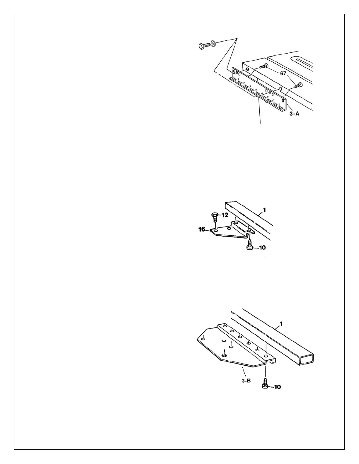
Step 2A Fig. 1A
Using two ¼-28x½” Hex Head Bolts (#10) fasten the
Inner Rear Bracket (#16) to the underside of the Inner
Rail Tube (#1).
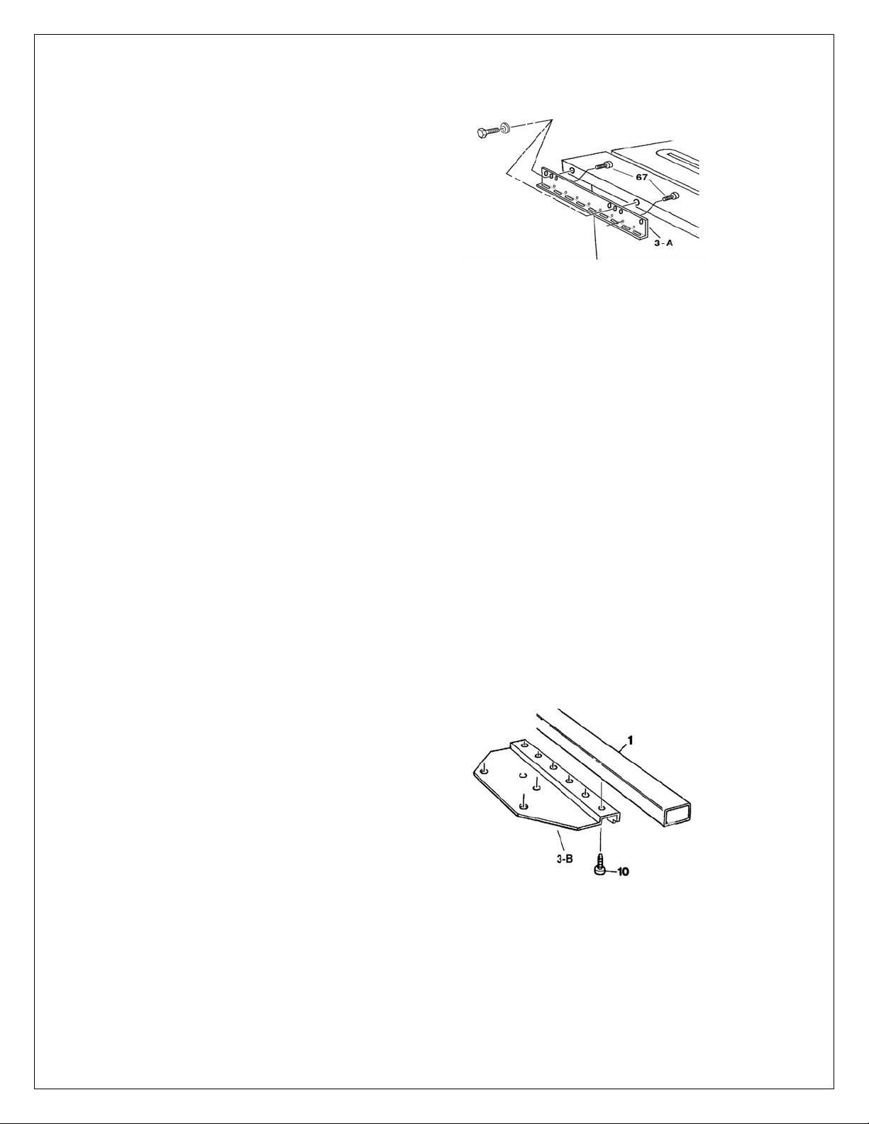
Step 3A Fig. 1A
Matching the six holes in the mounting Bracket
(#3B) with the six holes in the underside of the Inner
Rail Tube, Use ¼-28x½” Hex Head Bolts (#10) to
fasten the Mounting Bracket to the Inner Rail tube.

1/11/2005
4

1/11/2005
5
Step 4A Fig. 1A
Match the four holes in the Rear Outer Leg Mount
(#6) with the four holes in the underside of the Outer
Rail Tube (#2). Fasten using ¼-28x½” Hex Head
Bolts (#10). Fasten the Front Outer Leg Mount (#5)
to the underside of the Outer Rail Tube with three
Hex Head Bolts (#10).
Step 5A Fig. 1A
Insert Legs (#7) into the Leg Mounts (#5&6) and
snug the ¼-20x⅜” Set Screws (#11) to be tightened
later. Attach the Rear Cross Brace (#15) and the two
diagonal braces (#8) between the rail assemblies
using 5/16-18x¾” Hex Head Bolts (#12) and Square
Nuts (#13). Snug up and tighten later. Refer to Fig.
1A for brace locations.
Step 6A Fig. 1A
Attach Mounting Bracket (#3B) to the Mounting
Plate (#3A) and secure with two ¼-20 x 1” Button
Head Bolts (#67) and T-knobs (#44).
1/11/2005
6
Fasten the Mounting Plate to the saw’s table using
the bolts* (see Fig. 1A) from the previously removed
extension wing or other appropriate fasteners to fit
your saw’s table.
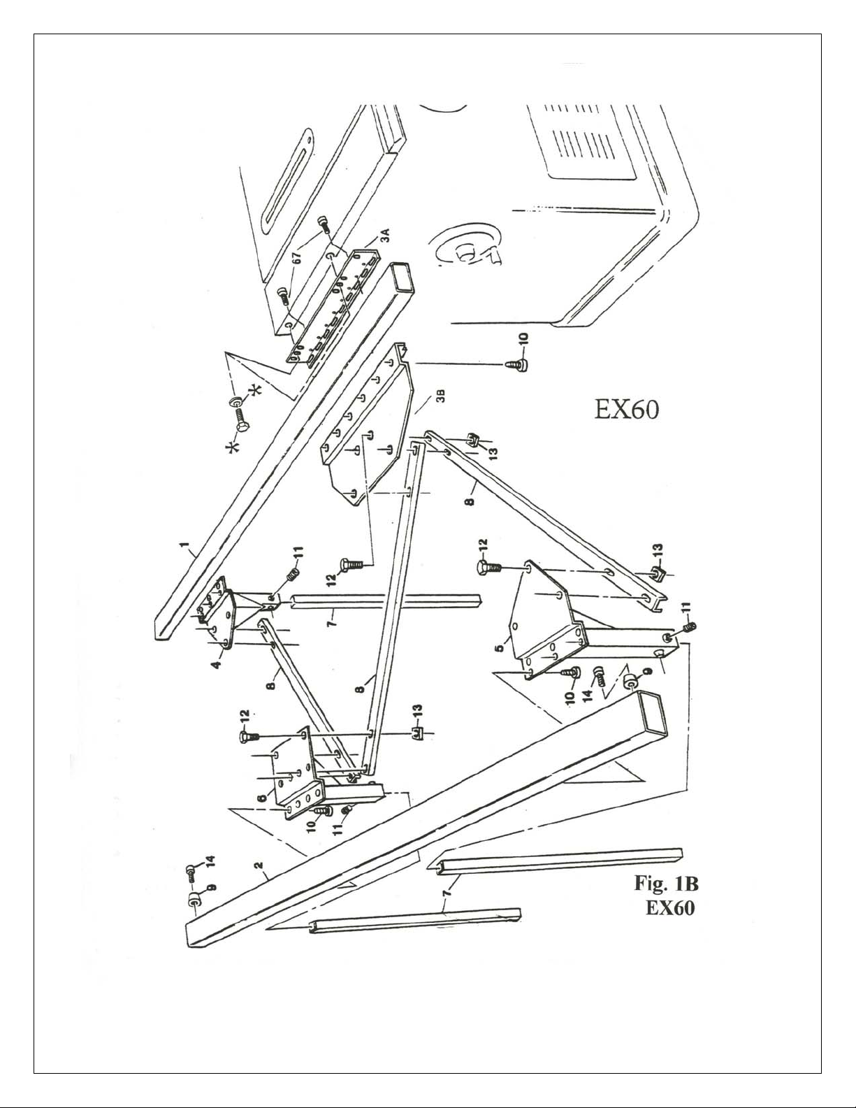
Rail Assembly Fig. 1B
Steps 1B to 6B are for Model EX60 ONLY
Caution! When using ratchets, wrenches and other
leveraged tools for tightening screws and/or bolts, be
careful not to over-tighten.
NOTE: In these instructions the ‘front’ of the
machine always refers to where the operator normally
stands.
Step 1B Fig. 1B
Table Saw Installation: There are two possible ways
to install the EX40 Sliding Table for use with a table
saw.
3. You can attach the Mounting Plate (#3A) to
the lip of the left hand extension wing by
drilling two holes in the lip of the wing, or
4. by first removing the extension wing and
attaching the Mounting Plate to the edge of
the saw’s table.
If your work consists of cutting panels with a
Melamine finish, it is suggested to minimize
vibration in the work piece, that the Mounting Plate
be attached as close to the saw blade as possible by
first removing the left hand extension wing.
NOTE: The left hand end of the front and rear guide
rails for the saw’s rip fence cannot project to the left
of the saw’s table to which the Mounting Plate is to
be attached. The rails must be moved to the right or
be cut off accordingly.
Position the Mounting Plate so that it is more or less
centered on the saw blade arbor. Attach the Mounting
Plate approximately 1/8” below the top surface of the
saw’s table.
Check the alignment of the boltholes. If the existing
holes in the Mounting Plate do not fit your table saw,
drill the necessary holes in the Mounting Plate, or in
the edge of the saw’s table.
NOTE: When bolted to the saw the Mounting Plate
must be at 90°to the table surface of the machine. If
the edge of the machine’s table is not square, the
Mounting Plate must be shimmed.
Guide Rail Assembly
IMPORTANT! Refer to Fig. 1B
Note that the mounting surface ‘steps up’ from the
triangular surface on part #4 and ‘steps down’ on part
#5. These parts are not interchangeable. Do not
confuse them.
Step 2B Fig. 1B
Fasten the Rear Inner Leg Mount (#4), using the row
of holes closest to the bend in the mount, to the
underside of the Inner Rail Tube (#1) with ¼-28x½”
Hex head bolts (#10). Insert a Leg (#7) into the Leg
Mount and temporarily snug the Set Screws (#11).
Step 3B Fig. 1B
Matching the six holes in the mounting Bracket
(#3B) with the six holes in the underside of the Inner
Rail Tube, Use ¼-28 x ½” Hex Head Bolts (#10) to
fasten the Bracket to the Rail Tube.
1/11/2005
7

1/11/2005
8
Step 4B Fig. 1B
Match the four holes in the Rear Outer Leg Mount
(#6) with the four holes in the underside of the Outer
Rail Tube (#2). Fasten using ¼-28 x ½” Hex Head
Bolts (#10). Fasten the Front Outer Leg Mount (#5)
to the underside of the Outer Rail Tube with three ¼“
Hex Head Bolts (#10).
Step 5B Fig. 1B
Insert Legs (#7) into the Leg Mounts (#5&6) and
snug the Set Screws (#11) to be tightened later.
Attach the three diagonal braces (#8) between the rails
assemblies using a 5/16-18 x ¾” Hex Head Bolts (#12)
and Square Nuts (#13). Snug up and tighten later.
Refer to Fig. 1B for brace locations.
Step 6B Fig. 1B
Attach Mounting Bracket (#3B) to the Mounting
Plate (#3A) and secure with two ¼-20 x 1” Button
Head Bolts (#67) and T-knobs (#44).
1/11/2005
9
Table Assembly For EX40 & EX60
Step 7 Fig. 2
The Lower Lip (#21) is attached to the inboard edge
of the Table (#20) using two ¼-20 x 1¼” Socket head
bolts (#27). Do not tighten.
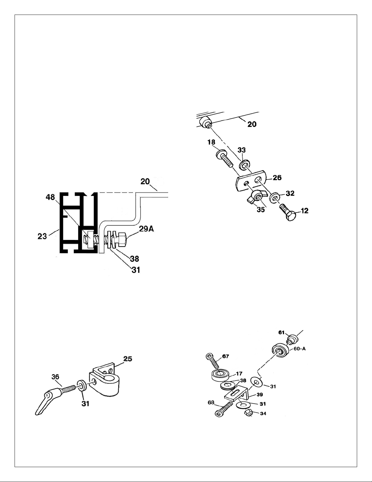
Step 8 Fig. 2
To attach the Angle Adjustment Rail (#23) to the side
of the Table (#20). Place a ¼” Lock Washers (#38)
and a ¼” Flat Washers (#31) on two ¼-20 x ¾” Hex
Head Bolts (#29A). Insert through holes in table. See
Fig. #2. Thread a T-nut (#48) on each Hex Head bolt
leaving enough space between the edge of the Table
and the T-nut to be able to slide the Angle
Adjustment Rail onto the T-nuts. Note: The top
surface of the Angle Adjustment Rail must be
installed in the same plane and be flush with the top
of, and be centered on, the Table. Tighten the Hex
Head Bolts.
Step 9 Fig. 2
Thread a Locking Lever (#36) with ¼” Washers
(#31) into Table Mounts (#25). Attach the Table
Mounts to the front and rear edge of the Table (#20)
using two ¼-20 x ½” Button head Bolts (#30) and ¼”
Washers (#31).
Step 10 Fig. 2
Thread a Stop (#18) through the Stop Tab (#26) and
into the Wing Nut (#35). Place the Spring Washer
(#33) on the boss on the front edge of the Table.
Place the Stop Tab on the boss and secure with a 5/16-
18 x ¾” Hex Head Bolt (#12) and a 5/16” Flat Washer
(#32) so that the flat head of the Stop is facing
towards the Table. A fence Stop assembly is also
mounted on the boss at the rear edge of the Table.
Step 11 Fig. 3
Assemble the two Lower Bearings. Each consists of a
small Bearing (#17), Lower Bearing Bracket (#39),
¼” Button Head Bolt (#67), two Lock Washers (#38),
Washer (#31) and Lock Nut (#34).
Step 12 Fig. 3
Using ¼-20 x x1¼” Button Head Bolts (#68), Flat
Washer (#31), Bearing Spacers (#61) and Lock Nuts
(#34), attach the Lower Bearing Assemblies and two
outboard horizontal Bearings (#60A) under the
outboard (left) side of the Table (#20).

1/11/2005
10

1/11/2005
11

1/11/2005
12
Step 13
Slide the Table onto the end of the two Guide Rails,
ensuring that the lower Lip (#21) is hooked under the
Inner Rail Tube (#1) and the Lower Bearings (#17)
are underneath the Outer Rail Tube (#2).
Step 14 Fig. 1
Attach Rubber Bumpers (#9) at each end of the Outer
Rail, using 8-32 x ½” Phillips Screws (#14).
Step15 Fig. 2
Attach Wiper Brushes (#70) to the front and rear
edges of the Table using 8-32 x ½” Phillips Screws
(#14). Adjust the brushes to touch the top surface of
the Outer Guide Rail.
Adjustments
The Inboard Horizontal Bearings (#60B) are factory
installed using ¼-20 x 1” Button Head Bolts (#67),
Bearing Spacers (#61) and Eccentric Adjusters (#62).
With Bolts ‘finger tight’ turn and hold the Adjusters
to position the Bearings against the inner side of the
Outer Rail Tube (#2). Then tighten the Bolts.
Position the Lower Bearings (#17) so they touch the
underside of the Outer Rail Tube, Ensure that the
table slides freely. If desired you can increase drag by
adjusting the Bolts (#27) holding the Lower Lip
(#21) which rubs against the underside of the Inner
Rail Tube (#1). To prevent the Bolts loosening, due
to vibration, Secure with NyLock Nuts (#34).
With the Table on the Guide Rails, position the
factory installed Brake Lever (#63) by turning its
Eccentric Adjuster (#62) and securing it with Bolt
(#67). When the Brake Lever is pulled towards the
front of the Table it should lock against the Outer
Rail Tube and prevent the Table from sliding.

1/11/2005
13
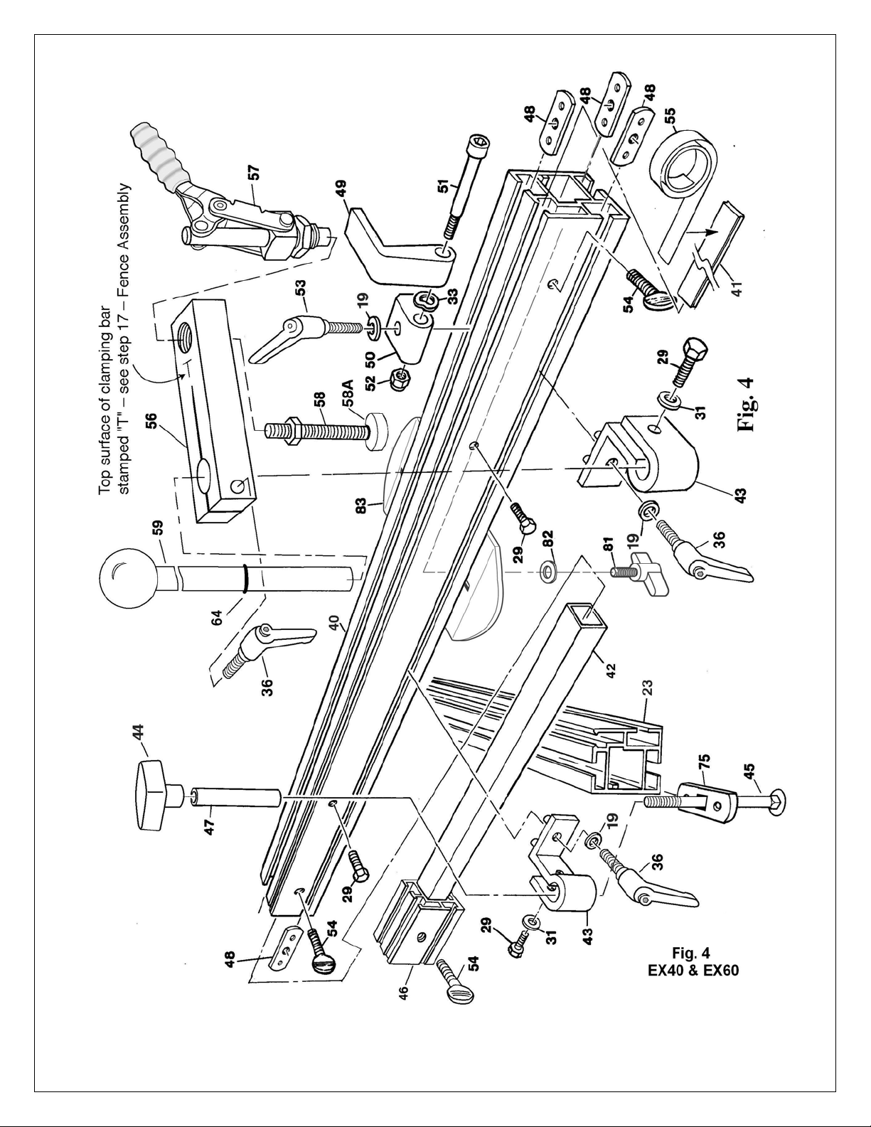
Fence Assembly for EX40 & EX60
Step 16 Fig. 4
Assemble Locking Lever (#36), Washers (#19 &
#31), ¼-20 x ¾” Hex Head Bolt (#29), and T-nut
(#48) to a Fence Mount (#43). Slide one of these
assemblies into each end of the T-slot in the backside
of the Fence (#40).
Step 17 Fig. 4
The Toggle Clamp (#57) is screwed into the
Clamping Bar (#56) and held in position by its jam
nut. NOTE: The top surface of the Clamping Bar
is stamped with a ‘T’. The Pivot Post (#59) is
inserted through the Clamping Bar (#56), which is
held in place by a Locking Lever (#36). Set the Fence
(#40) on the Table (#20). At the right hand end of the
Fence, align the Fence Mount (#43) and the Table
Mount (#25). Drop the Pivot Post, with the O-Ring
above the Fence Mount, through the aligned mounts.
Snug the ¼-20 x ¾” Bolt (#29) on the Fence Mount
for a close fit. The lower end of the Pivot Post is held
secure in the Table Mount by tightening the Locking
Lever (#36) that clamps the lower end of the Pivot
Post.
Step 18 Fig. 4
Insert Carriage Bolt (#45) through the Locking Plate
(#75), and the Locking Tube (#47) which, in turn, is
inserted though the Fence Mount (#43). Swing the
Fence and slide the Locking Plate into the T-slot on
the top surface of the Angle Adjustment Rail (#23).
Snug up the T-Locking Knob (#44).
NOTE: To prevent damage to the top surface of
the Angle Adjustment Rail, the lower end of the
Locking Tube should be made flush with the
lower surface of the Fence Mount and held there
by tightening the Hex Head Bolt (#29).
Step 19 Fig. 4
Insert the Extension Bars (#42) into the outboard end
of the Fence ($40) and into the front end of the Angle
Adjustment Rail (#23) and secure them with Thumb
Screws (#54). Place the Extension Blocks (#46) on
the exposed end of the Extension Bars and secure
with Thumb Screws (#54).
Step 20 Fig. 4
Assemble the Flip Stops as indicated using a Flip
Stop Mount (#50), 1-1/8” Locking Lever (#53), 6mm
Flat Washer (#19), T-nut (#48), ⅜” Shoulder Bolt
(#51), Flip Stop Finger (#49), Wave Washer (#33)
and NyLock Nut (#52).
Step 21 Fig. 4
Install the assembled Flip Stops on the Fence by
sliding the T-nut (#48) into the T-slot on the top
surface of the Fence (#40). The Flip Stops can be
held in position by tightening the Locking Lever
(#53).
1/11/2005
14

1/11/2005
15
Affix the adhesive Measuring Tape (#55) to the Tape
Measure Slide (#41). To set the Measuring Tape on
the Fence, you may want to start the tape at the 1”
mark, as you are not likely to have the right hand end
of the Fence touching the left side of the saw blade.
The Tape Measure Slide is held in position by two ¼-
20 x ¾” Hex Head Bolts (#29C), which are threaded
into the backside of the Fence (#40).
Set-up:
Getting the Sliding Table level with the top of
the saw table.
With the Fence installed at the front edge of the
sliding table, position the Table so that the Fence is at
the front edge of the saw’s table. Slide the right hand
end of the Fence to the side of the miter guide slot in
the saw table. Secure the Fence to the sliding table.
Push the sliding table towards the rear of the table
saw. The bottom of the fence should just clear and
remain parallel to the top of the top surface of the
saw’s table. This can be accomplished by adjusting
the height of the legs (#7) in their Leg Mounts (#4,5
& 6) and the height of the Mounting Plate (#3a) that
is attached to the edge of the saw table.
Also, the right hand end of the Fence should track the
full length of the miter guide slot and not drift to the
right or left of the slot. To adjust for this: Loosen the
Hex Head Bolts (#12) that hold the Braces to the
Front and Rear Outer Leg Mounts (#5 & 6) and shift
the Outer Rail Tube (#2) to the left or right as
required. Re-tighten the Hex Head Bolts. Check the
tracking. Re-adjust as required.
NOTE: When making this adjustment, make sure
that the sliding table does not bind against the
Inner Rail Tube.
Adjustments:
Using a square set the Fence 90°to the saw blade.
Turn the Stop Tab (#26) to the vertical position and
adjust the Stop (#18) to stop the Fence in this
position. Lock the Stop with the Wing Nut (#35). The
Stop Tab can be turned down when the 90°stop
position is not required.
Insert the Degree Slide (#24) into the top of the
Angle Adjustment Rail (#23). The Degree Slide is
held in place with two Hex Head Bolts (#29B see
Fig.2) that are threaded into the inboard side of the
Angle Adjustment Rail. With the Fence at 90°to the
saw blade adjust the Degree Slide and/or the Angle
Adjustment Rail so the ‘0’ degree mark is in line with
the face of the Fence.
NOTE: When you change saw blades, the
thickness of the blade can vary from one saw
blade to the next. If you are relying on the
measuring tape for accuracy remember to adjust
the Tape Slide accordingly.
1/11/2005
16
When crosscutting with the fence positioned at the
back end of the sliding table, the EX60 sliding table
will crosscut approximately 62”. With approximately
52” of the material clearing the rear of a 10” saw
blade. With the EX40, 39” will clear the blade. In
both cases another 10” will be cut, and remain
alongside the blade.
Using the Sliding Table with the table saw.
NOTE: In these instructions, the ‘front end’ of the
Table refers to the front side of the front side of the
assembled sliding table where the operator normally
stands.
The fence on the sliding table can be positioned at
either the front or back of the table. Both ends of the
table are equipped with fence pivot and stop tab
assemblies.
When viewed from the front of the sliding table the
fence pivots are located at both the front and back
right hand corner of the table. When the fence is
moved from the front to the back end of the table, the
position of the Locking Tube Assembly and the Pivot
Post Assembly are switched.
When crosscutting with the fence positioned at the
front end of the table, the EX60 Sliding Table will
crosscut approximately 35” the EX40 27”. With the
table saw turned-off and the saw blade at a complete
standstill, pull the sliding table as far to the front as is
possible and place the material to be cut against the
face of the fence, making sure that the material to be
cut is well in front of the saw blade. Use the toggle
clamp to secure the material to be cut, making sure
that the material cannot move or shift out of position.
With the fence positioned at the rear of the sliding
table and the face of the fence pulled in front of the
saw blade, use the brake lever to hold the sliding
table in position. Place the material to be cut on the
sliding table, pushed against the face of the fence.
With the toggle clamp, secure the material, making
sure that it cannot move or shift out of position.
If the material being cut is wider than the sliding
table is deep, the extension bar and block can be
pulled out from the front end of the angle adjustment
rail and be locked in position, to support the material
that overhangs the front end of the sliding table.
Only when the material to be cut is in place and
secured with the toggle clamp, turn on the saw. Keep
both hands and all loose clothing well away from the
revolving saw blade. To make the cut, push the work
piece and the brake lever will release. If necessary, or
when required, the fence can be removed and the
sliding table can be locked in position on the guide
rail tubes.
*********************************************************
The sides of the cross members in the EX40 and EX60 Sliding Tables have ledges that can be used to support shop
made inserts. These will prove to be helpful when it is desirable to have part, or all, of the top of the table filled in.
The inserts, constructed from ¾” thick MDF or plywood, and covered with a plastic laminate, will require shims to
bring their top surface level with the top of the table. The inserts can be secured to the table using wood screws.

1/11/2005
17
Parts for EXAKTOR®
EX40 and EX60
Sliding Tables
Part # Description Qty
ST01 Inner Guide Rail 1
ST02 Outer Guide Rail 1
ST03AMounting Plate 1
ST03BMounting Bracket 1
ST04 Inner Leg Mount (EX60 only) 1
ST05 Front Outer Leg Mount 1
ST06 Rear Outer Leg Mount 1
ST07 Leg (2 for EX40, 3 for EX60) 2/3
ST08 Brace
(2 for EX40, 3 for EX60) 2/3
ST08 Rubber Bumper 2
ST10 Hex Head Bolt ¼-28 x 1/2” 16
ST11 Set Screw ¼-20 x 3/8”
(4 for EX40, 6 for EX60)
ST12 Hex Head Bolt 5/16-18 x¾” 14
ST13 Square Nut
5/16-18 12
ST14 Phillips Screw 8 -32 x ½” 6
ST15 Rear Cross Brace, (EX40 only) 1
ST16 Rear Bracket, EX40 only 1
ST17 Lower Bearing, ⅝” Dia. 2
ST18 Stop ¼-20x1” 2
ST19 Flat Washer
6mm 4
ST20 Table 1
ST21 Table Lower Lip 1
ST22 Anti Friction Slip (installed) 1
ST23 Angle Adjustment Rail 35”long1
ST24 Degree Slide 1
ST25 Table Mount 2
ST26 Stop Tab 2
ST27 Socket H/Bolt ¼-20 x 1¼” 2
ST29 Hex Head Bolt ¼-20 x ¾”8
ST30 Button Head Bolt ¼-20 x ½” 4
ST31 Washer Flat ¼” 17
ST32 Washer Flat
5/16” 2
ST33 Wave Washer ⅜” 5
ST34 NyLock Nut ¼-20 8
ST35 Wing Nut ¼-20 2
ST36 Locking Lever – ¾’ stud 5
Part # Description Qty.
ST38 Split Lock Washer ¼” 6
ST39 Lower Bearing Bracket 2
ST40 Fence 64.5” long 1
ST41 Tape Measure Slide 64.5” 1
ST42 Extension Bar 2
ST43 Fence Mount 2
ST44 T-Knob ¼-20 3
ST45 Carriage Bolt ¼-20 x 3½” 1
ST46 Extension Block 2
ST47 Locking Tube 1
ST48 T-Nut 7
ST49 Work Stop Finger* 2
ST50 Work Stop Mount* 2
ST51 Shoulder Bolt* ⅜-18 x 2” 2
ST52 NyLock Nut*
5/16-18 2
ST53 Locking Lever* 1-⅛” stud 2
ST54 Thumb Screw ¼-20 x 1” 5
ST55 Tape Measure 1
ST56 Clamping Bar 1
ST57 Toggle Clamp 1
ST58 Adjustment Spindle 1
ST58ARubber Tip 1
ST59 Pivot Post with Knob 1
ST60 Bearing – 1⅛” 6
ST61 Bearing Spacer 7
ST62 Eccentric Adjuster 3
ST63 Brake Lever 1
ST64 O-Ring
– 5/8” Dia. 1
ST67 Button Head Bolt ¼-20 x1” 7
ST68 Button Head Bolt ¼-20 x1¼ 2
ST69 EXAKTOR®Logo Label 3
ST70 Wiper Brush 2
ST75 Retainer 1
ST81 Thumb Screw 1
ST83 Support Plate 1
*There are parts for two Work Stops
included with the Sliding Table.

1/11/2005
18
Sliding Table Accessories
Work Stop Assembly
EXAKTOR®Sliding Tables are shipped with parts to
assemble two Work Stops.
ST33 Wave Washer ⅜” 1
ST19 Flat Washer 1
ST48 T-Nut 1
ST49 Work Stop Finger 1
ST50 Work Stop Mount 1
ST51 Shoulder Bolt 1
3/8-18 x 2”
ST52 Ny-Lock Nut 1
5/16-18
ST53 Locking Lever 1
1⅛” stud
Insert the 3/8” Shoulder Bolt through a Work Stop
Finger (#49), Wave Washer (#33) and Work Stop
Mount (#50). Secure the Bolt with a Ny-Lock Nut
(#52) and tighten to eliminate any play between the
Finger and the Mount.
Insert the treaded stub of a Locking Lever (#53)
through 6mm Washer (#19) and Work Stop Mount
(#50) into a T-Nut (#48). Leave enough slack to slide
the T-Nut into the T-slot on the topside of the Fence.
With the Measuring Tape synchronized to the saw
blade, the Work Stop is placed in position relative to
the saw blade by ‘flipping’ the Finger onto the top of
the Fence against the desired measurement on the
Measuring Tape and locking the Work Stop Mount in
place

1/11/2005
19
Sliding Table Accessories
Panel Support Assembly
EXAKTOR® Sliding Tables are shipped with parts to
assemble one Panel Support,
Part # Description Qty
ST48 T-Nut 1
ST81 Thumb Screw 1
ST31 Flat Washer ¼” 1
ST83 Support Plate 1
Insert the threaded stub of Thumb Screw (#81)
though a ¼” Washer (#31) and up through the
underside of Support Plate (#83) into a T-Nut (#48).
Leave enough slack to slide the T-Nut into the T-slot
on the underside of the Fence (#40).
The Panel Support can be positioned for use under
the Crosscut Fence (#40) and/or under the Extension
Block (#46).
1/11/2005
20
Sliding Table Accessories
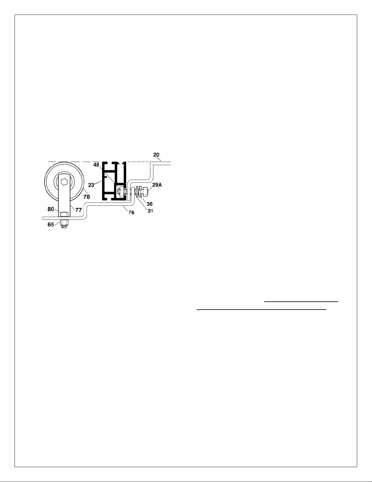
Outboard Roller Assembly
The Outboard Roller is an optional accessory for the
EXAKTOR®Sliding Table.
Part # Description Qty.
ST76 Roller Bracket 1
ST77 Roller Support 2
ST78 Roller 1
ST80 Hex Head Bolt 4
1/4-20 x 1/2”
ST65 NyLock Nut 4
1/4-20
To attach the Roller Bracket (#76) to the Bearing
Support (#28) use the two, currently in place, ¼” Hex
Head Bolts (#29A), Lock Washers (#38) and Flat
Washers (#31) inserted through the elongated holes
in the Roller Bracket and the lower lip of the Bearing
Support. Thread the T-Nuts (#48) on the Hex Head
Bolts (#29A) leaving enough slack to slide the T-
Nuts into the T-Slot on the inboard side of the Angle
Adjustment Rail (#23)
Using four ¼” Hex Head Bolts (#80) and four
NyLock Nuts (#65) attach the two Roller Supports
(#77) to the Roller Bracket (#76). Insert the Roller
(#78-S) between the Roller Supports by compressing
the Roller’s spring-loaded axel.
NOTE: The top surface of the Roller and the
Angle Adjustment Rail must be in the same plane
and be level with the top surface of the Table. If
necessary, shim between the Angle Adjustment
Rail and The Bearing Support. Tighten the two
Hex Head (#29A) Bolts.
This manual suits for next models
1


