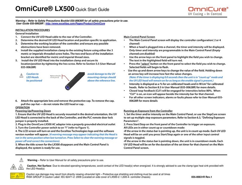
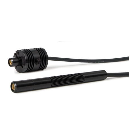
Excelitas Technologies OmniCure LX500-2 V2 Installation and operating manual

OmniCure® LX500 Series
LED UV Curing Solutions
Applicable for the following UV LED Head Controller models:
Model Part Numbers
LX500-2 V2
(supports up to two LED Heads)
010-00520R
LX500-4
V2
(supports up to four LED Heads) 010-00521R
LX500-2
(supports up to two LED Heads)
010-00369R
LX500-4 (supports up to four LED Heads) 010-00375R
Installation/Reference Guide
Excelitas Canada Inc.
2260 Argentia Road
Mississauga (ON)
L5N 6H7 Canada
+1 905.821.2600
www.excelitas.com
035-00628R Rev 2

OmniCure® LX500 Series
UV Curing Solutions
http://www.excelitas.com/omnicure
Excelitas Canada Inc. 2022
All rights reserved
035-xxxxxR, rev.1
ii
035-00628R
Installation/Reference Guide
035-00628R
Excelitas Canada Inc. 2022
All rights reserved
No part of this publication may be reproduced, transmitted, transcribed, stored in a retrieval system or translated
into any language in and form by any means without the prior written consent of Excelitas Canada Inc. every
effort has been made to ensure information in this manual is accurate, however, information in this manual is
subject to change without notice and does not represent a commitment on the part of the authors.
Trademarks:
OmniCure® is a trademark of Excelitas Canada Inc. All rights reserved. All other product names are trademarks of
their respective owners. All product or software photos shown are for reference only and are subjected to change
without notice.
Made in Canada. Doc. No. 035-00628R

OmniCure® LX500 Series
UV Curing Solutions
http://www.excelitas.com/omnicure
Excelitas Canada Inc. 2022
All rights reserved
035-xxxxxR, rev.1
iii
035-00628R
Table of Contents
1Introduction ...................................................................................................................... 1
2Safety Precautions/ User Warnings...................................................................................... 2
2.1 Glossary of Symbols................................................................................................................................................2
2.2 Safety Precautions ..................................................................................................................................................2
3Optical Safety Data ............................................................................................................ 4
4Getting Started.................................................................................................................. 5
4.1 Package Contents ...................................................................................................................................................5
4.2 UV LED Controller and Head Images .....................................................................................................................8
5Installing the Hardware ...................................................................................................... 9
5.1 General Installation .................................................................................................................................................9
5.2 Clamp Installation and Removal.............................................................................................................................9
5.3 Changing Lenses................................................................................................................................................... 10
5.4 Storing LED Head and Lens Assemblies .............................................................................................................. 10
5.5 Installation Component Images............................................................................................................................ 10
6Operation........................................................................................................................ 12
6.1 Powering Up and Powering Down........................................................................................................................ 12
6.2 Understanding the Controller Display.................................................................................................................. 13
6.3 Closed Loop Feedback.......................................................................................................................................... 16
6.4 Defining Exposure Parameters............................................................................................................................. 16
6.5 Running an Exposure from the Controller............................................................................................................ 19
6.6 Using the PC Interface with USB Connection ...................................................................................................... 19
6.7 Interfacing with a PLC........................................................................................................................................... 19
6.8 Using the Foot Pedal............................................................................................................................................. 21
7Troubleshooting ...............................................................................................................23
7.1 Symptoms and Possible Causes ...........................................................................................................................23
7.2 Error Codes............................................................................................................................................................24
8Care and Maintenance ...................................................................................................... 26
8.1 Cautions and Handling..........................................................................................................................................26
8.2 Cleaning Materials ................................................................................................................................................26
8.3 Cleaning the LED Head and Lens Assembly ........................................................................................................ 27
8.4 Cleaning the Controller......................................................................................................................................... 27
8.5 Calibrating a UV LED Head................................................................................................................................... 27
8.6 Viewing Log Files ..................................................................................................................................................28
8.7 SD Cards................................................................................................................................................................28
9Technical Specifications.....................................................................................................32
9.1 Environmental Conditions ....................................................................................................................................32
9.2 Controller Specifications.......................................................................................................................................32
9.3 UV LED Head Specifications................................................................................................................................. 33
10 Regulatory Compliance .................................................................................................... 34
10.1 Product Safety and Electromagnetic Compatibility: ........................................................................................... 34
10.2 China RoHS ........................................................................................................................................................... 35
10.3 WEEE Directive ......................................................................................................................................................37

OmniCure® LX500 Series
UV Curing Solutions
http://www.excelitas.com/omnicure
Excelitas Canada Inc. 2022
All rights reserved
035-xxxxxR, rev.1
iv
035-00628R
11 Warranty......................................................................................................................... 38
11.1 Checking Your Warranty Status ........................................................................................................................... 38
11.2 Replacement UV LED Module Warranty.............................................................................................................. 38
11.3 Returning your LX500 System to Excelitas Technologies for Service ................................................................. 38
12 Contact Information ......................................................................................................... 40
Figures
Figure 1 UV LED Head Controller (front)...................................................................................................................................8
Figure 2 UV LED Head Controller (back)...................................................................................................................................8
Figure 3 UV LED Head................................................................................................................................................................8
Figure 4 Lens/LED Head Connection ...................................................................................................................................... 10
Figure 5 Recommended Clamp Position..................................................................................................................................11
Figure 6 Typical Installation Applications.................................................................................................................................11
Figure 7 Extension Rod Application ..........................................................................................................................................11
Figure 8 PLC Connector (looking at Controller)....................................................................................................................... 19
Figure 9 PLC digital output equivalent circuit.......................................................................................................................... 21
Tables
Table 1 PLC Connector Pin Out................................................................................................................................................ 21
Table 2 Error Codes ..................................................................................................................................................................25
Table 3 Environmental Conditions ...........................................................................................................................................32
Table 4: Controller Specifications ............................................................................................................................................ 33

OmniCure® LX500 Series
UV Curing Solutions
http://www.excelitas.com/omnicure
Excelitas Canada Inc. 2022
All rights reserved
035-xxxxxR, rev.1
1
035-00628R
1Introduction
The OmniCure® LX500 series represents a new standard in UV LED Curing. It gives you the power, control, and
reliability never before available in such a form factor, providing configuration flexibility to suit any application for
end users and integrators alike.
The UV LED Head Controller allows optical output to be controlled manually via touch pad control, or by PLC or PC
(Virtual COM Port) USB interface. The UV LEDs are enclosed within the UV LED Head which provides excellent
spectral and power output. The UV LED Head has a typical lifetime in excess of 20,000 hours of accumulated 'on’
time.
The output power emission of the available UV LED Head is adjustable in 1% increments from 5% to 100% to
provide light for your application. In order to set your OmniCure LX500 series at specific irradiance levels (W/cm2),
we suggest running trials to optimize the results for the UV cured glues and adhesives used.
In the Excelitas Technologies family of UV LED light systems, all systems offer the same high level of innovation,
quality and reliability that our customers have come to expect. OmniCure® has combined next generation optical
engineering, state-of-the art electronics and fibre-optics to produce sophisticated technologies that employ light.
Today, OmniCure® is a leading developer of light-based systems for sectors ranging from manufacturing to bio-
medicine, and is unmatched in commitment to quality and service.
This manual covers the following models:
LX500-2 V2 010-00520R
LX500-4 V2 010-00521R
LX500-2 010-00369R
LX500-4 010-00375R
Excelitas Technologies recommends reading this guide to discover all features of the OmniCure® LX500 series
systems, and how to use them.
Note: Refer to OmniCure® LED Head Assembly Specification Guide 035-00730R, 035-00638R for LED Head
specifications.

OmniCure® LX500 Series
UV Curing Solutions
http://www.excelitas.com/omnicure
Excelitas Canada Inc. 2022
All rights reserved
035-xxxxxR, rev.1
2
035-00628R
2Safety Precautions/ User Warnings
2.1 Glossary of Symbols
Caution risk of danger – consult accompanying documents.
Risk Group
WARNING: UV emitted from this product. Avoid eye and skin exposure to unshielded product.
WARNING: Possibly hazardous optical radiation emitted from this product. Do not stare into
operating lamp.
Input/ Output Signals
Input Signal
CAUTION, Hot Surface
CAUTION, Risk of Electrical Shock
2.2 Safety Precautions
This series of cautions and warnings relate to the installation, operation and maintenance of the OmniCure®
LX500System. They are also presented throughout this Installation/Reference Guide as applicable.
WARNING
Do not stare directly at the light emitted from the LED array. This may be harmful, resulting in eye
injury. Always use UV protective eyewear as indicated below. Additionally, protect any exposed skin
with appropriate clothing or shielding as required.
Warning: UV protective eyewear must meet the following recommended optical specifications:
•Spectral range; 350-440nm
•Optical Density ≥ 6
Warning: Should the OmniCure® LX500 System be used in a manner not specified by Excelitas
Technologies, the protection provided by the equipment may be impaired.
The UV LED Head operation can be affected if handled incorrectly. Never touch the protective lens
cover assembly of the UV LED Head. The presence of skin oils may result in a decrease in system
performance.
Always ensure the power supply is turned off prior to disconnecting or re-connecting the UV LED
Head.

OmniCure® LX500 Series
UV Curing Solutions
http://www.excelitas.com/omnicure
Excelitas Canada Inc. 2022
All rights reserved
035-xxxxxR, rev.1
3
035-00628R
Warning:
Monitoring the system during automated operation:
The level of UV energy supplied by the OmniCure® LX500 System is sufficient to ignite flammable
substances. Therefore, when the unit is operated unattended in an automated environment, an alarm
function must be provided by the user to indicate a malfunction in the associated equipment used.
During installation the appropriate measures must be included to prevent any such occurrence.
Warning:
Always use this product with the external power supply and power cord set provided. Ensure the
external power supply cord is connected to a grounded 3-pin outlet only. Any substitution of these
components will invalidate regulatory certification of this product and may impair operating safety.

OmniCure® LX500 Series
UV Curing Solutions
http://www.excelitas.com/omnicure
Excelitas Canada Inc. 2022
All rights reserved
035-xxxxxR, rev.1
5
035-00628R
4Getting Started
4.1 Package Contents
Your package contains the following:
•UV LED Head Controller
LX500-2 V2 2-Channel(010-00520R) or LX500-4 V2 4-Channel(010-00521R) or LX500-2 2-Channel(010-
00369R) or LX500-4 4-Channel(010-00375R)
•Door lock jumper (018-00648R)
•DC power supply (290-00041R)
•UV protective eyewear (854-00001R)
Carefully unpack the unit and store the packing material for future use.
In addition to the Controller, you will require one to four LED Heads and Lenses, depending on your configuration.
Other optional components are available that may be sourced separately or may be purchased from Excelitas
Technologies. Check with Excelitas Technologies to determine the appropriate components for your requirements.
The following table provides the part numbers of component parts:
Item
Part Number
V3 LED Heads
365nm x 55mm UV HEAD HDMI V3 019-00398R
365nm x 125mm UV HEAD HDMI V3 019-00399R
385nm x 55mm UV HEAD HDMI V3 019-00400R
385nm x 125mm UV HEAD HDMI V3 019-00401R
395nm x 55mm UV HEAD HDMI V3 019-00402R
395nm x 125mm UV HEAD HDMI V3 019-00403R
405nm x 55mm UV HEAD HDMI V3 019-00404R
405nm x 125mm UV HEAD HDMI V3 019-00405R
MAX LED Heads
365nm x 55mm LED UV Head, Inc Clamp Sub Assembly 019-00286R
365nm x 125mm LED UV Head, Clamp Assembly Not included 019-00287R
385nm x 55mm LED UV Head, Inc Clamp Sub Assembly 019-00288R
385nm x 125mm LED UV Head, Clamp Assembly Not included
019-00289R
400nm x 55mm LED UV Head, Inc Clamp Sub Assembly 019-00293R
Lenses
3mm focusing lens for 365nm/385nm 810-00053R
6mm focusing lens for 365nm/385nm
810-00054R
8mm focusing lens for 365nm/385nm 810-00060R
10mm focusing lens for 365nm/385nm
810-00061R
12mm focusing lens for 365nm/385nm 810-00066R
5mm Cylindrical Lens for 365nm/385nm
810-00078R
90 deg Adapter, 6mm spot, 365nm/385nm 810-00083R
90 deg Adapter, 8mm spot, 365nm/385nm
810-00084R
90 deg Adapter, 10mm spot, 365nm/385nm 810-00085R
3mm focusing lens for 400nm
810-00062R
6mm focusing lens for 400nm 810-00063R

OmniCure® LX500 Series
UV Curing Solutions
http://www.excelitas.com/omnicure
Excelitas Canada Inc. 2022
All rights reserved
035-xxxxxR, rev.1
6
035-00628R
8mm focusing lens for 400nm 810-00064R
10mm focusing lens for 400nm 810-00065R
Extension Cables
Extension cables: 1m 018-00642R
Extension cables: 3m 018-00643R
Extension cables: 5m 018-00644R
Extension cables: 10m 018-00645R
Accessories
Mounting clamp 019-00288R
Foot pedal switch assembly 014-00070R
LS100 Light Sensor - Irradiance 019-00237R
LS100P Light Sensor – Power 019-00297R
OmniCure® Light Meter System (LM2011/LS100) 010-00281R
Beam Positioning Kit
019-00131R
Calibration Kit – Irradiance 019-00299R
Calibration Kit – Power
019-00300R
A micro SD card is useful (but not supplied by Excelitas) to save log files for monitoring or to save settings files for
future re-use.

OmniCure® LX500 Series
UV Curing Solutions
http://www.excelitas.com/omnicure
Excelitas Canada Inc. 2022
All rights reserved
035-xxxxxR, rev.1
7
035-00628R
The following table can be used as a reference to determine compatibility between different versions of controllers
and LED Heads:
LED Head/ Controller Compatibility Matrix
Controller Part No. ->
010-00520R
010-00521R
010-00369R
010-00375R
010-00369R
010-00375R
Firmware Version ->
1.0.7 (or Higher)
1.0.6
V3 Heads
019-00398R - 365nm x 55mm
019-00399R - 365nm x 125mm
019-00400R - 385nm x 55mm
019-00401R - 385nm x 125mm
019-00402R - 395nm x 55mm
019-00403R - 395nm x 125mm
019-00404R - 405nm x 55mm
019-00405R - 405nm x 125mm
MAX
Heads
019-00286R - 365nm x 55mm
019-00287R - 365nm x 125mm
019-00288R - 385nm x 55mm
019-00289R -385nm x 125mm
019-00293R - 400nm x 55mm
Compatible
Limited Compatibility
Not Compatible
Notes:
•010-00375R LX500-4 4-Channel Controller (with Firmware 1.0.7 or higher) can support a maximum of 2
V3 UV LED Heads
•Refer to OmniCure® LED Head Assembly Specification Guide 035-00730R, 035-00638R for LED Head
specifications and related accessories

OmniCure® LX500 Series
UV Curing Solutions
http://www.excelitas.com/omnicure
Excelitas Canada Inc. 2022
All rights reserved
035-xxxxxR, rev.1
8
035-00628R
4.2 UV LED Controller and Head Images
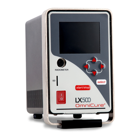
Note: LX500-4 shown.
Figure 1UV LED Head Controller (front)
Figure 2UV LED Head Controller (back)
Figure 3UV LED Head
Display
Radiometer
connection
MicroSD
card slot
Power
switch
Selection
arrows
Select item
highlighted in
display
Start/stop
exposure
USB
connection for
Power supply
connection
Connect PLC
controller or
door lock
jumper

OmniCure® LX500 Series
UV Curing Solutions
http://www.excelitas.com/omnicure
Excelitas Canada Inc. 2022
All rights reserved
035-xxxxxR, rev.1
9
035-00628R
5Installing the Hardware
5.1 General Installation
1. Determine the desired UV LED Head location and position based on the results of a series of testing and trials.
2. Determine the working location of the Controller, ensuring access to the AC power source does not cause any
possible obstruction with the power cable connection from the source to the controller. The main power
switch is located on the front panel of the unit. The unit should be placed so that the switch is convenient for
the operator to access.
3. If you are not integrating with an existing controller, ensure the door lock jumper is connected.
4. Connect the UV LED Head cable to the rear of the Controller. Only use Excelitas extension cables to extend
the reach of the UV LED Head.
5. If using a foot pedal switch, connect it to the corresponding input on Controller (e.g. Head 1, FP 1). Refer to
Figure 2.
6. Install the supplied installation clamp to the existing fixture using either the 3 metric threaded screw holes or
the 3 imperial threaded screw holes. The two end faces of the installation bracket are identified for metric and
imperial thread sizes. Though the clamp can be located in any position on the head, for optimum heat
dissipation resulting in optimum performance it is recommended that the clamp position on the head is as per
Figure 5.
7. Install the UV LED Head into the installation clamp and secure its location/position by tightening the hex
screw. Refer to Figure 6 for typical installation applications.
8. Attach the appropriate lens and remove the protective cap. To remove the cap, pull the cap-hat — do not
rotate the LED head or cap.
When not in use, reinstall the cap by holding the cap-hat and pushing it back over the head. This will prevent
any contamination to the lens when the head is not used for more than one day. Refer to Figure 4.
9. If you are not integrating with an existing controller, connect the door lock jumper between pins 24 and 25
(refer to Table 1). This jumper can be connected to your UV protective enclosure to prevent accidental UV
exposure during operation.
Closed contact – enable UV LED Head(s) output
Open contact – disable UV LED Head(s) output.
10. Connect the AC power cord in to the power supply and to a properly grounded AC outlet. For safe operation,
only use the power cord supplied or one with an equivalent rating, shield, and approvals.
11. Connect the power supplies DC barrel connector to the back of the Controller.
Note: The UV LED Head connectors are locking. To disconnect them from the Controller, squeeze the tab on the
plastic shell.
5.2 Clamp Installation and Removal
1. Ensure the clamp locking screw (M4 x 10, Allen key size 3mm) is loose before slipping the clamp into the LED
lens and head assembly.
2. Slide the clamp over the lens housing and onto the head and tighten the locking screw. For optimal
performance and ease of changing lenses, position the clamp so the bottom face is located between the lens
housing crease and the reference line (first circular groove) on the head body. Refer to Figure 4 and Figure 5.
3. To remove the clamp loosen the locking screw and slide the clamp off the lens and head assembly.

OmniCure® LX500 Series
UV Curing Solutions
http://www.excelitas.com/omnicure
Excelitas Canada Inc. 2022
All rights reserved
035-xxxxxR, rev.1
10
035-00628R
5.3 Changing Lenses
Do not use any mechanical tool when removing or replacing the lens/housing.
Hand tighten only, do not over tighten as this will make the assembly difficult to remove.
The lens and housing are one subassembly. Do not attempt to remove the lens from the housing.
Ensure the system is off and the head has cooled to room temperature before changing the lens.
Holding the head firmly unscrew the lens housing and replace with desired replacement lens. Refer to Figure 4.
It is recommended to clean the replacement lens thoroughly prior to replacement. Refer to Section 8.3 Cleaning
the LED head and Lens assembly. When not in use, place protective cap over the lens.
5.4 Storing LED Head and Lens Assemblies
When not in use, store the head and lens assembly individually wrapped in a clean, lint free bag in a safe, dry place.
Never store multiple unwrapped head and lens assembly in the same bag, as they may become damaged if they
come in contact with each other.
5.5 Installation Component Images
Figure 4Lens/LED Head Connection
Lens
Place protective
cap over the lens
LED Head, threaded lens housing
Reference line (first
circular groo
ve)

OmniCure® LX500 Series
UV Curing Solutions
http://www.excelitas.com/omnicure
Excelitas Canada Inc. 2022
All rights reserved
035-xxxxxR, rev.1
11
035-00628R
Figure 5Recommended Clamp Position
Figure 6Typical Installation Applications
Figure 7Extension Rod Application
Clamp
Bottom of clamp should be
between threaded housing
crease and the reference line
Extension rod for use with
standard optical fixtures

OmniCure® LX500 Series
UV Curing Solutions
http://www.excelitas.com/omnicure
Excelitas Canada Inc. 2022
All rights reserved
035-xxxxxR, rev.1
12
035-00628R
6Operation
6.1 Powering Up and Powering Down
CAUTION:
Ensure that the Controller is turned “OFF” before connecting or disconnecting UV LED
Heads.
WARNING:
Before running an exposure, make sure all operators in the area are wearing appropriate eye
protection or the UV LED Heads are behind a UV blocking enclosure.
1. Ensure that the UV LED Head is securely mounted in the desired orientation, the UV LED Head is connected to
the back of the Controller, and the PLC remote door lock jumper is properly installed. Refer to Figure 2 and
Section 5, “Installing the Hardware”.
2. Verify that the Controller power supply is connected to a properly grounded AC outlet.
Warning – Do not use inadequate detachable power cords. Please refer power technical specification for
more detailed information
3. Turn the Controller power switch to “ON” (refer to Figure 1).
4. The LCD screen will turn on and the Excelitas Technologies logo and the software version number will appear.
A warning message may appear indicating that the Head is not in the same unit/head port position it was used
in previously. At this message press Select to clear the warning message or power off and correct the
connections.
5. When the title screen for the LX500 disappears and the Main Control Panel is displayed, the system is ready
for use. The Main Control Panel shows the current state of any connected UV LED Heads.
Caution – the UV LED Head can become very hot; avoid handling until the UV LED Head has
cooled (approx. 5 min) or use protective gloves.
Before connecting or disconnecting any UV LED Heads, ensure that the Controller is turned
“OFF”.
To power down the unit, turn the Controller power switch to “OFF”.
Note : The main power switch is located on the front panel. The unit should be placed so the switch is convenient
for the operator to access.

OmniCure® LX500 Series
UV Curing Solutions
http://www.excelitas.com/omnicure
Excelitas Canada Inc. 2022
All rights reserved
035-xxxxxR, rev.1
13
035-00628R
6.2 Understanding the Controller Display
Status Bar
The top left corner of the display shows the menu icon,
which allows you to switch between screens. When
nothing else on the screen is selected, the menu icon is.
The status bar may also display the following icons:
– indicates that the PLC door pin is open and LED
exposures have been disabled.
– indicates that the front panel interface has been
locked out. To lock the front panel, use the PLC inputs
or PC command. (Lock status is not stored between
power cycles)
(up or down arrow) – indicates that the unit is in
count up or countdown mode.
Menu
Press Select at any time to display the menu.
Use the arrows to change selection, then press Select.

OmniCure® LX500 Series
UV Curing Solutions
http://www.excelitas.com/omnicure
Excelitas Canada Inc. 2022
All rights reserved
035-xxxxxR, rev.1
14
035-00628R
Main Control Panel
Displays upon start-up; shows current state of each
connected UV LED Head (displays two or four channels
depending on Controller model).
The timer for each channel is how long (in seconds) the
UV LED Head will remain on when an exposure is
triggered. If the timer is displaying 0.0 seconds then the
unit is in “count up” mode and the UV LED Head will
remain on for as long as the enable signal is present. If
in count up mode, the timer value cannot be changed.
The intensity is represented by both a numerical value
and a bar graph. If calibrated for irradiance, the number
will be a decimal without a ‘W’, if a decimal number
with a W is shown, the head is calibrated for power
mode. The color of the intensity bar will be same as the
color code on the UV LED Head. The intensity will be
displayed as a percentage for un-calibrated heads or in
W/cm2 or W for calibrated heads (refer to Section 8.5,
”Calibrating a UV LED Head”).
Closed loop feedback will be engaged for intensities
below 100%. When closed loop feedback (CLF) is on,
an icon will appear beside the intensity bar for that
channel. The CLF icon appears when CLF is actively
controlling the output of the head. If the CLF icon
disappears before the completion of an exposure, then
CLF has reached the upper limit it can adjust for and is
no longer functional. If CLF usage is desired, it is
recommended that you use an intensity of 80% or less.
The bottom of the screen shows the last event. If you
have an SD card installed this event will be saved to a
log file. (refer to Section 8.6,”Viewing Log Files”).
When the system experiences an alarm, the alarm icon
beside the Head number will turn red and an alarm
message will pop up.
StepCure
Use to control the UV LED Head operation for
sequence programming and S2000 compatibility. For
more information, see Section 6.4,”Defining Exposure
Parameters”.

OmniCure® LX500 Series
UV Curing Solutions
http://www.excelitas.com/omnicure
Excelitas Canada Inc. 2022
All rights reserved
035-xxxxxR, rev.1
15
035-00628R
Settings
Displays current system statistics. If necessary, use the
arrow keys to select and change any field.
•Time and Date
•PLC Delay Timing and Head association –
add a positive or negative delay to the
Programmable Sync Out pin. By default, the
PLC delay timing is off, pressing the right
arrow button will flash the head the PLC
delay is to be associated with. Press up or
down to change the head association. The
PLC delay timing is adjustable in 10ms
increments from 0ms to +/-30,000ms.
•PLC Logic – invert the PLC input and output
signal logic. Only the door lock logic is not
inverted. Note: When changing, the
interface will lock due to the signal flip.
Ensure you can control the PLC lock signal
before toggling this setting. Can be
corrected via PC interface.
•Language – switch the language displayed on
the LCD screen. Currently only English is
supported.
LED Head Information
Displays current programming for each connected UV
LED Head:
•WL – wavelength in nm
•Hours – accumulated operational hours
•Cal Hr – Number of calibrated hours
remaining.
•Temp – present temperature in °C
•Max – maximum allowable temperature (in
ºC) before an alarm is triggered
•Detect – detects the presence of a UV LED
Head in that channel:
- NC – Not connected at startup
- Lost – Head disconnected during use
- OK – Head connected and communicating
•Error – Error code (“0” indicates no error).
Refer to Section 7.2,”Error Codes”.
•Mode – indicates if channel is in count up or
countdown mode. Use the arrows to select
and edit this field. All values will change
simultaneously as the LX500 only support
one count mode for all Heads.

OmniCure® LX500 Series
UV Curing Solutions
http://www.excelitas.com/omnicure
Excelitas Canada Inc. 2022
All rights reserved
035-xxxxxR, rev.1
16
035-00628R
Calibration
Used to initiate and display the calibration process.
Horizontal access is the intensity percentage setting,
vertical access automatically scales and is the
corresponding irradiance in W/cm2 or power in W.
See Section 8.5, ”Calibrating a UV LED Head”.
SD Card Maintenance
Displays contents of inserted SD card.
The LX500 uses three files: two log files (refer to
Section 8.6, ”Viewing Log Files”) and a settings file
(refer to Section 6.4, “Defining Exposure Parameters”).
Save allows the current settings to be saved to the
default filename. When you select files you will see a
menu depending on the type of file that allow you to
load settings, update the firmware, or delete files.
To open a directory, highlight it and press Select. If in a
sub directory, press Select on …. to go up a level. Only
five subdirectories deep is supported by the LX500.
The Usage bar shows the capacity of the SD card; the
middle number reflects the current free space on the
card.
6.3 Closed Loop Feedback
This symbol means that the LED is currently being closed loop feedback controlled. Every time an intensity
adjustment is made, whether by front panel or PC control, a new set-point must be acquired. This occurs 500ms
after the LED is turned on, and is used during every subsequent exposure. If your exposure timer is less than 500ms,
this set-point will never be obtained. Once the intensity adjustment limit is reached, CLF will be disabled due to an
inability to increase the output intensity. When this symbol is displayed, CLF is active on the associated channel.
6.4 Defining Exposure Parameters
Programming an exposure
Use the Main Control Panel to change the timer or intensity for each UV LED Head:
•Use the arrow keys to highlight the field you wish to change. The text in the highlighted field will turn red.
•Press Select to select the field you wish to change. Selected fields will begin to flash.
•Use the up and down arrow keys to change the value of the field. Holding down an arrow key will increase how fast
the value changes.
Programming multiple steps or multiple heads
Use the StepCure screen to configure input signals to trigger a step profile of one or more heads. StepCure allows
for:
This manual suits for next models
8
Table of contents
Other Excelitas Technologies Controllers manuals

Excelitas Technologies
Excelitas Technologies OmniCure LX500 User manual

Excelitas Technologies
Excelitas Technologies OmniCure SC Series Installation and operating manual

Excelitas Technologies
Excelitas Technologies OmniCure SC0750 Installation and operating manual

Excelitas Technologies
Excelitas Technologies OmniCure LX500 User manual

Excelitas Technologies
Excelitas Technologies OmniCure LX500 Installation and operating manual