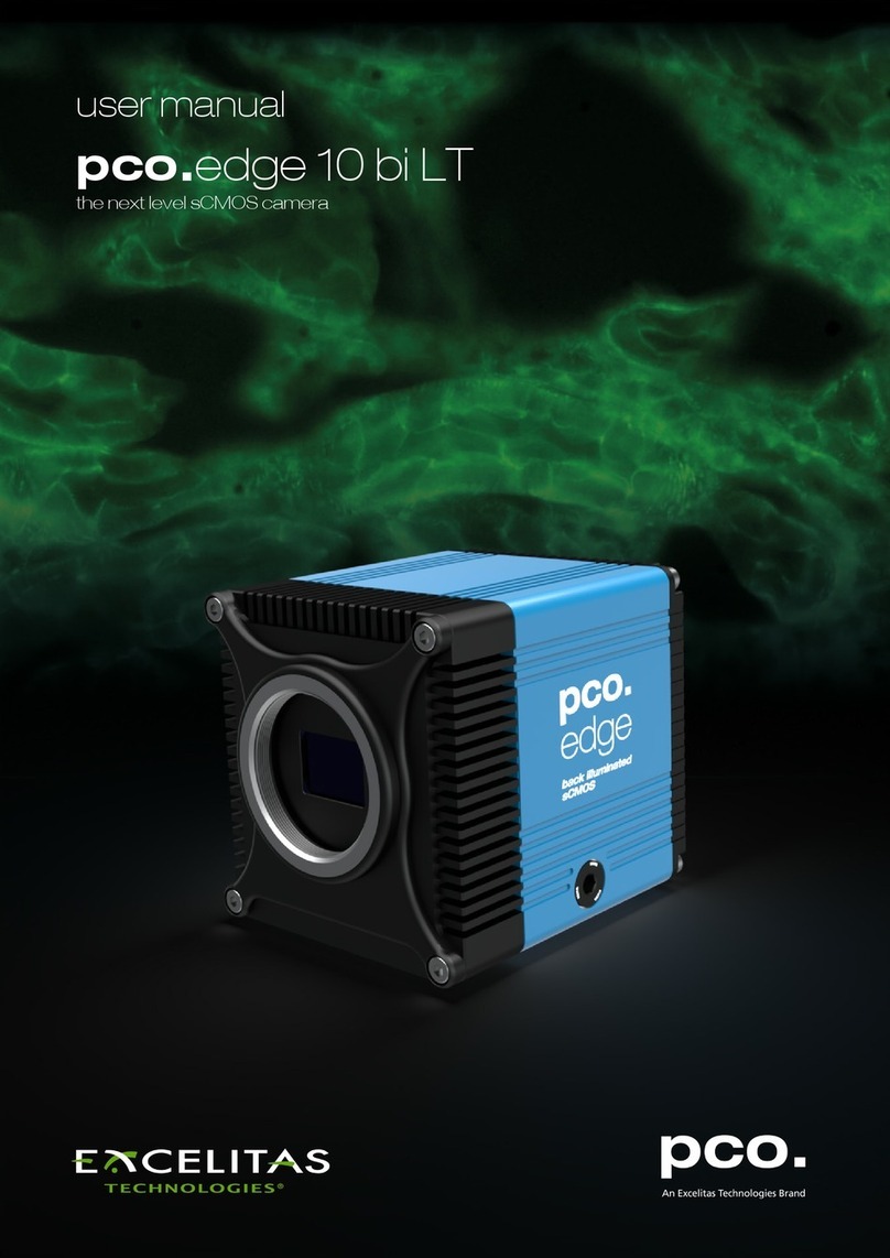
Excelitas Technologies pco.pixelfly 1.3 SWIR User manual

pco.pixelfly™ 1.3 SWIR
versatile VIS - SWIR camera
user manual

Excelitas PCO GmbH asks you to carefully read and follow the instructions in this document.
For any questions or comments, please feel free to contact us at any time.
telephone: +49 (0) 9441 2005 50
fax: +49 (0) 9441 2005 20
postal address: Excelitas PCO GmbH
Donaupark 11
93309 Kelheim, Germany
email: [email protected]
web: www.pco.de
pco.pixelfly™ 1.3 SWIR user manual 1.0.0
Released September 2023
©Copyright Excelitas PCO GmbH
This work is licensed under the Creative Commons Attribution-NoDerivatives 4.0 International License. To
view a copy of this license, visit http://creativecommons.org/licenses/by-nd/4.0/ or send a letter to Creative
Commons, PO Box 1866, Mountain View, CA 94042, USA.
pco.pixelfly™ 1.3 SWIR
pco.pixelfly™ 1.3 SWIR user manual 1.0.0 2

Contents
1 Safety 4
2 System components 5
2.1 Camera pco.pixelflyTM 1.3SWIR .................................... 6
2.2 USBinterface............................................... 7
2.3 Lensmountadapters .......................................... 7
2.3.1 C-mountadapter......................................... 7
2.3.2 F-mountadapter......................................... 8
2.3.3 TFL-mountadapter ....................................... 9
2.4 MachVissoftware ............................................ 10
2.5 Cables................................................... 10
3 Camera overview 11
3.1 Camerainterfaces ............................................ 11
3.2 Dataandpowerinterface ........................................ 11
3.3 LEDs.................................................... 12
3.4 Triggerandstatusinterfaces ...................................... 12
4 Operation modes 14
4.1 Globalshutter............................................... 14
4.2 Triggermodes .............................................. 15
4.3 Acquiremode............................................... 17
5 Operation 19
5.1 Systemrequirements .......................................... 19
5.2 Quickstartguide............................................. 20
6 Camera mechanics 21
6.1 Mechanicaloutlines ........................................... 21
6.2 Mounting ................................................. 22
7 Software 23
7.1 Softwarerequirements.......................................... 23
7.2 USB3.0/3.1driverinstallation...................................... 23
7.3 Downloadcorrectiondata........................................ 24
8 Specifications 26
9 Troubleshooting 28
10 Warranty 29
11 Recycling 30
12 About Excelitas PCO 31
pco.pixelfly™ 1.3 SWIR
pco.pixelfly™ 1.3 SWIR user manual 1.0.0 3

1 Safety
This camera system is a scientific measuring equipment and is designed for use by technicians,
engineers, and scientists. The camera may only be used according to the instructions of this
manual. Provisions, limitations, and operating conditions stated in this manual must be respected.
Unauthorized modifications and alterations of the device are forbidden for safety reasons.
DAMAGED POWER CABLE OR POWER PLUG: Danger to life due to electric shock. Each time
the camera is used, check the power cable for damage.
ELECTRIC SHOCK WARNING DUE TO VOLTAGE PARTS INSIDE: Risk of injury due to electric
shock. Never slide any items through slits or holes into the camera.
MOISTURE: Risk of injury due to electric shock if moisture enters the camera. To avoid the risk
of water condensation, protect the camera against extreme changes of ambient temperature.
TRIPPING HAZARD: Risk of injury from tripping over loose cables. Never position the cable in a
way that it could become a tripping hazard.
HUMIDITY, DUST OR RADIATION: Humidity, dust or X-rays could damage the camera. Never
operate the camera in humid or dusty environments or in places with high levels of X-ray
radiation.
SHOCK AND VIBRATION: To avoid damaging the camera, it must be firmly mounted and
protected against strong shocks or vibrations. Use the camera’s mounting threads to secure it.
LENS MOUNTING: Do not force the lens onto the camera. Screw in the lens gently to avoid
thread damage.
LIQUIDS DAMAGE CAMERA: If liquids have penetrated the device: Switch the camera off
immediately, detach it from power and contact PCO’s customer support.
DAMAGED CAMERA HOUSING: If the camera has been dropped or the camera’s housing is
damaged: Switch the camera off immediately, detach it from power and contact PCO’s
customer support.
pco.pixelfly™ 1.3 SWIR Chapter 1
pco.pixelfly™ 1.3 SWIR user manual 1.0.0 4

2 System components
The following standard components are included in your scope of delivery:
Article Picture Details
pco.pixelflyTM 1.3 SWIR chapter 2.1
C-mount adapter chapter 2.3.1
Cables (USB C-C) chapter 2.5
There is a range of optional camera accessories available for the pco.pixelflyTM 1.3 SWIR series:
Article Picture Details
USB interface card chapter 2.2
F-mount adapter chapter 2.3.2
Interface cables
(SMA - BNC) chapter 2.5
Continued on next page
pco.pixelfly™ 1.3 SWIR Chapter 2
pco.pixelfly™ 1.3 SWIR user manual 1.0.0 5

Continued from previous page
Article Picture Details
TFL-mount adapter chapter 2.3.3
Please note that all pco.software products can be downloaded for free from the PCO website. For
more information see chapter 7.
2.1 Camera pco.pixelflyTM 1.3 SWIR
Thanks for choosing a pco.pixelflyTM 1.3 SWIR camera. The pco.pixelflyTM 1.3 SWIR is a high
performance machine vision camera due to its special InGaAs image sensor which is sensitive in
the shortwave infrared, near infrared and visible range of the electromagnetic spectrum. It shows
a favorably high sensitivity in the whole spectral range with up to 90 % in the shortwave infrared
part. The small pixels enable the use of small magnification optics in microscopy and a low dark
current for even longer exposure times.
Main Features
•VIS & SWIR sensitivity (350 nm to 1700 nm)
•Small pixel size (5 µm x 5 µm)
•Long exposure times (due to low dark current)
•Excellent peak QE (of 90 %)
•(Easy to use) USB 3.1 Gen 1 data interface
•TEC controlled sensor temperature
•Global Shutter (camera)
•InGaAs sensor technology
•Resolution 1280 x 1024 pixel
•Max. frame rate 72 fps @ 1.3 Mpixel
•Genicam supported
Please read the instructions given in this document carefully. It contains useful information and
advice to operate the camera in intended way. If there are any questions, please feel free to contact
PCO or the local representative.
Areas of application
Brightfield microscopy Inspection
Fluorescence microscopy Material selection
Continued on next page
pco.pixelfly™ 1.3 SWIR Chapter 2
pco.pixelfly™ 1.3 SWIR user manual 1.0.0 6

Continued from previous page
Areas of application
Structured illumination microscopy (SIM) Material sorting
Wafer inspection Biometrics
High-Speed bright field ratio imaging Industrial quality inspection
Intravital microscopy Waste sorting
In-vivo microscopy Thermography
Industrial packaging Semiconductor inspection
Food processing quality control
2.2 USB interface
CAUTION: Please make sure that your PC provides enough power to operate the camera. If not,
it can not be guaranteed that the camera works as intended.
2.3 Lens mount adapters
PCO cameras have an interchangeable lens adapter system to use the camera with different
standard lenses. The adjustment of the lens mount can be done by the user.
2.3.1 C-mount adapter
The C-mount adapter is screwed in the front of the camera and fixed with two allen screws (marked
in red). In order to set the standard back focal distance of the C-mount (17.526 mm), screw in the
C-mount ring until it stands out 1.8 mm from the camera front (see figure 2.1, right).
~1.8 mm
Adjustable
Figure 2.1: C-Mount installation.
pco.pixelfly™ 1.3 SWIR Chapter 2
pco.pixelfly™ 1.3 SWIR user manual 1.0.0 7

Use a suitable lens with a large aperture for fine adjustment.
Follow these steps for the fine adjustment:
•Set the lens focus to infinity and look at an object which is far away.
•Rule of thumb: The distance to the object must be at least 200 times the focal length of the
lens. The further away, the better.
•Then turn the lens mount in until the object is sharp.
•Look at an object which is positioned at the minimum working distance of your lens (as
described in the corresponding datasheet).
•Set the lens focus to the minimum working distance (the opposite direction of infinity).
•Now adjust the lens mount until this object is sharp.
•Repeat the above steps until the focus is consistently sharp in both positions.
CAUTION: The allen screws are designed for a maximum torque of 1 Nm. All torque values in
this manual are recommendations.
8.2 mm
1/1.8“
2/3“
1“
4/3“
Figure 2.2: sensor size vs. image
circles of various C-mount lenses.
Keep in mind that C-mount lenses can cause shadings at the
edges of large-sized sensors.
Most C-mount lenses can illuminate a maximum image circle
in the range of 9 mm (1/1.8’’) to 22 mm (4/3’’) diameter only.
The pco.pixelflyTM 1.3 SWIR has a sensor diagonal of 8.2
mm.
To achieve less shaded images, the ROI function can be used
to limit the resolution of the sensor when using lenses with
smaller image circles than the sensor diameter.
2.3.2 F-mount adapter
The optional F-mount adapter is screwed in the front of the camera and fixed with by the lower
adjustment ring of the adapter. In order to set the accurate back focal distance of the F-mount
(46.50 mm), the position of the adapter can be adjusted. The same procedure as described in
chapter 2.3.1 is applicable.
pco.pixelfly™ 1.3 SWIR Chapter 2
pco.pixelfly™ 1.3 SWIR user manual 1.0.0 8

Back focal
distance fine
adjustment
Automatic
diaphragm
Figure 2.3: F-mount description.
PCO’s proprietary F-mount adapter supports lenses with an automatic diaphragm. It manually sets
the lens aperture by turning the upper adjustment ring of the adapter. F-mount lenses without an
automatic diaphragm can be connected to the mount at the camera, but the aperture cannot be
changed.
Matching lenses with automatic diaphragm
Manufacturer Lens type
Nikon Nikkor Type D, Nikkor Type G
Zeiss ZF.2 (Otus, Milvus, Interlock, Distagon, Planar)
Tamron Type 35 mm: A012, A007, A009, A011, F012, F013
Type APS-C(H): B001, B005, G005
2.3.3 TFL-mount adapter
The optional TFL-mount adapter is screwed in the front of the camera and fixed with two allen
screws (marked in red). In order to set the standard back focal distance of the TFL-mount (17.526
mm), screw in the TFL-mount ring until it stands out around 1.8 mm from the camera front (see
figure 2.4, right). The TFL mount supports lenses with a maximum sensor diagonal of 28.3 mm.
pco.pixelfly™ 1.3 SWIR Chapter 2
pco.pixelfly™ 1.3 SWIR user manual 1.0.0 9

~1.8 mm
Adjustable
Figure 2.4: TFL-mount installation.
The fine adjustment is done in the same way as described in chapter 2.3.1.
2.4 MachVis software
The MachVis Software can be used to select a suitable lens for a camera or optical setup. With
its help it’s possible to find fitting lenses for variable types of cameras. More information can be
found on the web.
2.5 Cables
The pco.pixelflyTM 1.3 SWIR is delivered with a USB interface cable for power supply and data
transfer.
Article Length Description Scope of delivery
USB cable 2 m USB 3.1 type C-C, DELOCK 83668 Included
Interface cable 0.3 m Coaxial cable type SMA-BNC Available on request
Please note that other cables may not be suitable for your camera. If a cable is equipped with a
screwable mount, make sure to attach it to the camera accordingly.
NOTE Only use cables which are approved by PCO. Otherwise full functionality cannot be
guaranteed.
pco.pixelfly™ 1.3 SWIR Chapter 2
pco.pixelfly™ 1.3 SWIR user manual 1.0.0 10

3 Camera overview
The following chapter provides an overview of the pco.pixelflyTM 1.3 SWIR.
3.1 Camera interfaces
4
3
2
1
Figure 3.1: pco.pixelflyTM 1.3 SWIR rear panel interfaces.
Interfaces
1 trigger and status via SMA connectors (input)
2 trigger and status via SMA connectors (output)
3 status LEDs
4 power and data interface via USB 3.1 Gen 1
Hardware setup
Connect the camera to the PC with the included USB-C cable.
•The USB cable manages both: the data transfer from the camera to the PC and the power
supply for the camera.
•If the PC does not have a USB-C port: use the included USB interface card/frame grabber
(see chapter 2.2).
Connect the SMA plugs with coaxial cables for status or trigger functionality to the equipment (see
chapter 3.4).
3.2 Data and power interface
The pco.pixelflyTM 1.3 SWIR is available with the following interfaces:
Camera Interface Interface connector
pco.pixelflyTM 1.3 SWIR USB 3.1 Gen 1 USB-C socket
pco.pixelfly™ 1.3 SWIR Chapter 3
pco.pixelfly™ 1.3 SWIR user manual 1.0.0 11

3.3 LEDs
The functionality of the LEDs on the rear panel of the camera is listed in the following table.
LED ”arm/rec” LED ”status” Meaning
OFF Orange Camera is booting
OFF Green Camera is ready for operation
OFF Red Error
Orange Green Arm camera / rec state off
Orange blinking Green Recording
OFF OFF Camera without power
3.4 Trigger and status interfaces
The pco.pixelflyTM 1.3 SWIR provides different operation modes (see chapter 4). These can be
controlled and monitored via control signals at the rear panel of the camera. In total, there are four
trigger and status interfaces. Of these, there are two signal inputs (frame trigger, acquire enable)
and one signal output (exposure).
Functional behavior
The assignment of functionality of the signals at the SMA interfaces can be done by software (e.g.
pco.camware). The inputs and outputs can be either switched ON (with different functionality) or
OFF.
Parameter Option
SMA 1 input exposure trigger auto sequence, soft trigger, external exposure start,
external exposure control, low latency trigger
off
signal polarity rising (default)
SMA 2 input acquire enable external, sequence, auto
off
signal polarity low (default)
SMA 3 output signal trigger on
signal polarity high (default)
SMA 4 output status exposure on
signal polarity high (default)
The default values are listed in the table above.
A functional description of the trigger modes and corresponding output signals is given in chapter
4.
pco.pixelfly™ 1.3 SWIR Chapter 3
pco.pixelfly™ 1.3 SWIR user manual 1.0.0 12

Status signals
Status signals are signals generated by the camera for synchronization purposes.
The exposure signal (SMA 4) is active during exposure and inactive at all other times.
Electrical properties
Input (1 = Exposure Trigger; 2 = Acquire Enable)
Type digital
Level 3.3 V LVTTL (5 V tolerance)
Coupling DC
Impedance 1 k�
Slew rate > 1 V/ms
Output (3 = Status Echo; 4 = Status Exposure)
Type digital
Level 3.3 V LVTTL
Coupling DC
pco.pixelfly™ 1.3 SWIR Chapter 3
pco.pixelfly™ 1.3 SWIR user manual 1.0.0 13

4 Operation modes
The camera can be used in different modes. These will be introduced in the following chapter.
4.1 Global shutter
Image acquisition and readout with the pco.pixelflyTM 1.3 SWIR is based on global shutter mode.
That means, each pixel in the sensor begins and ends the exposure simultaneously. After the
exposure phase and a small defined time slot, the readout phase of the pixels starts directly.
During the readout phase, the next exposure phase can be started.
time
exposure
image i readout
image iexposure
image i+1 readout
image i+1
t=0 texp texp
tread tread
Figure 4.1: global shutter explanation.
The overall readout time of the sensor is determined by the line time, i.e. the time needed to
readout one line. Depending on the number of lines to be readout (ROI settings), the total time of
the readout phase can be calculated:
treadout =Nlines ·tline
With a line time of 13.5 µs and 1024 lines, the total readout time results to 14 ms.
Timing
The exposure and delay time (programmable time between acknowledge of a trigger input and
start of exposure) can be set in steps of one line time.
Camera Exposure time Delay time Step size
pco.pixelflyTM 1.3 SWIR 20 µs to 720 s 0 µs to 1 s 13.5 µs
pco.pixelfly™ 1.3 SWIR Chapter 4
pco.pixelfly™ 1.3 SWIR user manual 1.0.0 14

4.2 Trigger modes
The pco.pixelflyTM 1.3 SWIR incorporates several trigger modes. In this context trigger means
exposure trigger, i.e., the trigger signal that controls the exposure time of single image (light
integration time). Trigger modes can be set via software (e.g. pco.camware, SDK command),
trigger related input and output signals are accessible via the SMA interfaces (see chapter 3.4).
NOTE: Input and output signals polarity can not be changed.
Auto sequence mode
In the Auto Sequence mode, the camera determines the highest possible frame rate for the defined
exposure time and the time required for a frame readout. After a start command is given, the
sequential recording is started, until a stop command is given. These commands can be set by
software. Any signals at the trigger input (hardware I/Os) are irrelevant.
readout
nreadout
n+1
exposure
nexposure
n+1
time
Status exposure
(out)
sensor
exposure
sensor
readout
sequence
command stop
start
Figure 4.2: auto sequence explanation.
Soft(ware) trigger mode
Within this trigger mode, recording of single images can be triggered by software with corresponding
commands. In all other modes the soft(ware) trigger will be ignored.
External exposure start
In the external exposure start mode, single images are recorded with each rising or falling edge of
the signal at the input trigger interface (SMA 1). The resulting frame rate is defined by the frequency
of this trigger signal. However, the predefined exposure time and ROI settings affect the maximum
possible frame rate.
pco.pixelfly™ 1.3 SWIR Chapter 4
pco.pixelfly™ 1.3 SWIR user manual 1.0.0 15

time
Exposure trigger
(in)
Status exposure
(out)
accepted accepted rejected
Figure 4.3: external exposure start explanation.
The status exposure output indicates the time of the active exposure phase. The status busy
output indicates whether the camera is ready to process and accept a new trigger signal. A trigger
signal during active state of the signal status busy will be rejected.
If the rate of the external trigger input signal is close to the maximum possible frame rate (1 ms
difference), it will be random whether the trigger is accepted or not.
ttdb
tde
texp(signal)
Exposure trigger
(in)
Status busy
(out)
Status exposure
(out)
Sensor
exposure
time
Figure 4.4: exposure trigger.
Delay time Value
Delay exposure time tde 692 ns ±24 ns
Delay trigger to sensor exposure tdes 1100 ns ±100 ns
External exposure control
Within this trigger mode, the externally applied signal (SMA 1) defines the start and the duration of
the exposure time. A new exposure is started by rising or falling edge of the trigger signal and end
when the opposite edge is detected. The image sequence is completely controlled by the external
signal. Any defined delay and exposure time values are ineffective.
pco.pixelfly™ 1.3 SWIR Chapter 4
pco.pixelfly™ 1.3 SWIR user manual 1.0.0 16

The maximum exposure time of the camera is limited. The exposure time will be stopped automatically
if the maximum exposure time is reached.
time
Exposure trigger
(in)
Status exposure
(out)
accepted accepted rejected
Figure 4.5: external exposure control explanation.
The status exposure output indicates the time of the active exposure phase. A trigger signal during
active state of the signal status busy will be rejected.
If the rate of the external trigger input signal is close to the maximum possible frame rate (1 ms
difference), it will be random whether the trigger is accepted or not.
4.3 Acquire mode
The Acquire Mode is an additional instance to control image acquisition by an external signal.
Like a master signal, the acquire enable signal enables or disables a time slot in which images are
recorded according to the selected trigger mode.
There are two configurations of the acquire enable mode: auto and external.
If acquire enable mode is set to auto, any signal at the acquire enable input interface is ignored.
There is no logical connection between the input and the trigger modes.
If acquire enable mode is set to external, the camera records images only, if enabled by an
external acquire enable signal at SMA 2.
Example timing diagram: Trigger mode is set to external exposure start and acquire mode is set to
external mode. The image acquisition is paused once the acquire enable signal turns low, signals
at the external trigger input are ignored. Image acquisition is resumed as soon as the acquire
enable signals turns high.
pco.pixelfly™ 1.3 SWIR Chapter 4
pco.pixelfly™ 1.3 SWIR user manual 1.0.0 17

time
Status exposure
(out)
Acquire enable
(in)
rejectedaccepted accepted
Exposure trigger
(in)
Figure 4.6: acquire mode explanation.
pco.pixelfly™ 1.3 SWIR Chapter 4
pco.pixelfly™ 1.3 SWIR user manual 1.0.0 18

5 Operation
pco.
In the following chapter the system requirements in terms of connection and memory needed to
use the camera will be explained. The table below shows the required GPU memory for different
camera types and modes.
5.1 System requirements
System Requirements
Interface USB 3.1 Gen 1
The following values are suggested minimum requirements for the used PC to facilitate smooth
operation:
GPU Memory
Operation mode & sensor Resolution < 10 MPixel Resolution ≥10 MPixel
Single shutter monochrome ≥1 GB ≥2 GB
Single shutter color ≥2 GB ≥4 GB
Double shutter monochrome ≥2 GB ≥4 GB
pco.pixelfly™ 1.3 SWIR Chapter 5
pco.pixelfly™ 1.3 SWIR user manual 1.0.0 19

5.2 Quick start guide
The following instructions will guide the user through the first startup of the camera.
Install the latest version of pco.camware (see chapter 7) and PCO USB driver (chapter 2.2).
Connect the camera to the PC via the USB cable. Make sure that the status LED turns green.
The camera is ready for operation.
Start pco.camware.
The software should find your camera automatically. If not, the user can do a rescan to connect
with your plugged camera. The command Scan cameras can be accessed via the Main toolbar
or the Camera Overview window.
Menu -> Camera -> Rescan
A new view window should open automatically. The user can also open a new View Window
manually via the button New View Window located in the Main toolbar or the Camera
Overview window.
Menu -> View -> New View Window
Start the Live Preview by clicking the button in the Main toolbar or the Camera Overview
window. The arm/rec LED starts flashing in orange.
Menu -> Acquisition -> Live Preview
Right click in the View Window and apply Continuous Auto Range. The user may now have to
adjust exposure time of the camera as well as aperture and focus of the mounted lens.
The user should now see the object clearly in the View Window.
Note: Live Preview is useful for fast and easy camera adjustment and focusing. It does not record
or store images.
For more information, please check the user manual of pco.camware available at the PCO website.
pco.pixelfly™ 1.3 SWIR Chapter 5
pco.pixelfly™ 1.3 SWIR user manual 1.0.0 20
Table of contents
Other Excelitas Technologies Digital Camera manuals
Popular Digital Camera manuals by other brands

Olympus
Olympus Stylus 740 Brochure & specs
Kodak
Kodak Advantix 5800 MRX Zoom owner's manual

Sony
Sony DSC F505V - Cybershot 2.6MP Digital Camera operation instruction

Creative
Creative PC-CAM 920 Slim user manual
Epson
Epson ELPDC06 Document Camera For serial numbers beginning with LQZF - DC-06 Document... user guide
Concord Camera
Concord Camera 4340z quick start guide
