Excera EM8100 VHF User manual

DMR Mobile RadioEM8100 VHFUSER’S MANUAL

1 Contents Important Information 3 DMR Trunking Functions and Operations15Private Call15Group Call 18All Call 20Emergency Call 20Broadcast Call 20 Priority Call20Dispatch Station Call 20DMR Public Network Call 20DMR-MPT Call21Contacts 21Message22Status Message23Call Logs23Redail List and Callback List 23Vehicle Inquiry24ID Inquiry 24Status Filing 25 Roaming 25Scan 25Radio Saftety Information and RF Radiation Information8 Packing List8 Before Use 9 Ready to Use 9Product Controls 10LEDIindicator 12Status Icons 12Disabled Frequency 8 Functions and Operations13 Operation Mode13Product Information Display 13Time and Date SettingAlert Tone VibrationBacklightMenu Reset 13Programmable Keypad 14High Noise Reduction 14Time-out-Timer(TOT)14GPS Positioning13131313RF Energy Exposure InformationOperation Safety Recommendations4 5 14

Dispatch Station Call 30MPT Pubic Network Call30MPT-DMR Call31Call LogsRedail and Callback List Analog Conventional Functions and Operations 37DMO and RMO ModeSquelch level Optional Accessories Troubleshooting
Private Call 26Group Call 28All Call 30Emergency Call Broadcast Call 30Priority Call 30 MPT Trunking Functions and Operations26Contents Warranty and Maintains 40Scope of Warranty40
40
41
Warranty Card42Non of WarrantyDisclaimer Warranty Contents4030Emergency Warranty31Receiving and Responding to a CallLate AccessManual Input to Temporary GroupScan333233323131 Digital Conventional Functions and Operations 34Private Call,Group Call and All Call 34Emergency Call 34Message35Call Logs36Zone 3637373839 2

3Ic Note : Cet Appareil Est Conforme À La Partie 15 Des Règlements De La Fcc Et Aux Normes Rss De L’industrie Du Canada. Son Fonctionnement Est Soumis Aux Deux Conditions Suivantes : (1) Cet Appareil Ne Doit Pas Causer Des Interférences Nuisibles, Et (2) Cet Appareil Doit Accepter Toute Interférence Reçue, Y Compris Les Interférences Qui Peuvent Provoquer Un Fonctionnement Indésirable.. Le Fabricant N'est Pas Responsable Des Toutes Interférences Radio Ou Télévision Causées Par Des Modifications Non Autorisées Apportées À Cet Appareil. De Telles Modifications Peuvent Empêcher L’utilisateur D’utiliser L'appareil. Ic Note:This Device Complies With Part 15 Of The Fcc Rules And Industry Canada License-exempt Rss Standard(s). Operation Is Subject To The Following Two Conditions: (1) This Device May Not Cause Harmful Interference, And (2) This Device Must Accept Any Interference Received, Including Interference That May Cause Undesired Operation. The Manufacturer Is Not Responsible For Any Radio Or Tv Interference Caused By Unauthorized Modifications Or Change To This Equipment. Such Modifications Or Change Could Void The User’s Authority To Operate The Equipment.The Users Manual Or Instruction Manual For An Intentional Or Unintentional Radiator Shall Caution The User That Changes Or Modifications Not Expressly Approved By The Party Responsible For Compliance Could Void The User's Authority To Operate The Equipment. In Cases Where The Manual Is Provided Only In A Form Other Than Paper, Such As On A Computer Disk Or Over The Internet, The Information Required By This Section May Be Included In The Manual In That Alternative Form, Provided The User Can Reasonably Be Expected To Have The Capability To Access Information In That Form.Important InformationNote:
Ibefore using the two-way mobile radio, review the following important RF energy awareness and control information and operational instructions. Comply with this information and instructions in order to ensure compliance with RF exposure guidelines.e the capability to access information in that form.This two-way radio uses electromagnetic energy in the radio frequency (RF) spectrum to provide communications between two or more users over a distance. It uses RF energy or radio waves to send and receive calls. RF energy is one form of electromagnetic energy. Other forms include, but are not limited to, electric power, sunlight, and x-rays. RF energy, however, should not be confused with these otherforms of electromagnetic energy, which, when used improperly, can cause biological damage. Very high levels of x-rays, for example, can damage tissues and genetic material.Experts in science, engineering, medicine, health, and industry work with organizations to develop standards for exposure to RF energy. These standards provide recommended levels of RF exposure for both workers and the general public. These recommended RF exposure levels include substantial margins of protection. All two-way radios marketed in North America are designed, manufactured, and tested toensure they meet government-established RF exposure levels. In addition, manufacturers also recommend specific operating instructions to users of two-way radios. These instructions are important because they inform users about RF energy exposure and provide simple procedures on how to control it. Refer to the following websites for more information on what RF energy exposure is and how to control exposure to assure compliance with established RF exposure limits:http://www.fcc.gov/oet/rfsafety/rf-faqs.htmlhttp://www.osha.gov./SLTC/radiofrequencyradiation/index.html 4RF Energy Exposure Awareness And ControlInformation For Fcc Occupational Use RequirementsThis radio is intended for use in occupational/controlled conditions, where users have full knowledge of their exposure and can exercise control over their exposure to remain below RF exposure limits. This radio is NOT authorized for general population, consumer, or any other use.
!!
Changes or modifications not expressly approved by EXCERA could void the user's authority to operate the equipment.WARNINGCAUTIONImportant InformationRF Energy Exposure Information

To ensure bodily exposure to RF electromagnetic energy is within the FCC allowable limits for occupational use. Always adhere to the following basic guidelines:• The push-to-talk button should only be depressed when intending to send a voice message.• The radio should only be used for necessary work-related communications.• The radio should only be used by authorized and trained personnel. It should never be operated by children.• Do not attempt any unauthorized modification to the radio. Changes or modifications to the radio may cause harmful interference and/or cause it to exceed FCC RF exposure limits. Only qualified personnel should service the radio.• Always use only authorized accessories (antennas, control heads, speakers/mics, etc.). Use of unauthorized accessories can cause the FCC RF exposure compliance requirements to be exceeded.The information listed above provides the user with information needed to make him or her aware of a RFexposure, and what to do to assure that this radio operates within the FCC exposure limits of this radio.Occupational Safety Guidelines And Safety Training Information 5Federal Communications Commission RegulationsBefore it was marketed in the United States, the Digital mobile radio was tested to ensure compliance with FCC RF energy exposure limits for two-way mobile radios. When two-way radios are used as a consequence of employment, the FCC requires users to be fully aware of and able to control their exposure to meet occupational requirements. Exposure awareness can be facilitated by the use of alabel directing users to specific user awareness information. The radio has an RF exposure product label.Also, the Product Safety Manual and this Operator’s Manual include information and operating instructions required to control RF exposure and to satisfy compliance requirements.Important InformationOperation Safety Recommendations
6• Explosive Atmospheres — Just as it is dangerous to fuel a vehicle while its engine is running, be sure to turn the radio OFF while fueling the vehicle. If the radio is mounted in the trunk of the vehicle, DO NOT carry containers of fuel in the trunk. Areas with potentially explosive atmosphere are often, but not always, clearly marked. Turn the radio OFF when in any area with a potentially explosive atmosphere. It is rare, but not impossible that the radio or its accessories could generate sparks.• Interference To Vehicular Electronic Systems — Electronic fuel injection systems, electronic antiskid braking systems, electronic cruise control systems, etc., are typical of the types of electronic devices that can malfunction due to the lack of protection from radio frequency (RF) energy present when transmitting. If the vehicle contains such equipment, consult the dealer for the make of vehicle and enlist their aid in determining if such electronic circuits perform normally when the radio is transmitting.·ElectricBlastingCaps—Topreventaccidentaldetonationofelectricblastingcaps.DONOTusetwo-wayradioswithin1000feet(305 meters)ofblastingoperations.Alwaysobeythe“TurnOffTwo-WayRadios”(orequivalent)signspostedwhereelectricblastingcapsare beingused.(OSHAStandard:1926.900).·RadioFrequencyEnergy—Topreventburnsorrelatedphysicalinjuryfromradiofrequency energy, do not operate the transmitter when anyone outside of the vehicle is within the minimum safe distance from the antenna as specified in Table 1.·VehiclesPoweredByLiquefiedPetroleum(LP)Gas—Radioinstallationinvehiclespoweredby liquefied petroleum gas, where the LP gas container is located in the trunk or other sealed-off space within the interior of the vehicle, must conform to the National Fire Protection Association standard NFPA 58. This requires: ThespacecontainingtheradioequipmentmustbeisolatedbyasealfromthespacecontainingtheLPgascontaineranditsfittings. OutsidefillingconnectionsmustbeusedfortheLPgascontainer. TheLPgascontainerspaceshallbeventedtotheoutsideofthevehicle.Transmitter HazardsThe operator of any mobile radio should be aware of certain hazards common to the operation of vehicular radio transmissions. Possible hazards include but are not limited to:
!
WARNINGImportant Information

7Radio Frequency Interference·VehiclesEquippedwithAirbags—Fordriverandpassengersafety,avoidmountingtheradios control head (or any other component) ’above or near airbag deployment areas. In addition to driverside and passenger-side front-impact airbags, some vehicles may also be equipped with side-impact airbags. For occupant safety, verify the location of all airbags within the vehicle before installing theradio
equipment.FCC Part 15This device complies with Part 15 of the FCC Rules. Operation is subject to the following two conditions:1. This device may not cause harmful interference; and,2. This device must accept any interference received, including interference that may cause undesired operation.Industry CanadaThis device complies with Industry Canada license-exempt RSS standard(s). Operation is subject to the following two conditions: (1) this device may not cause interference, and (2) this device must accept any interference, including interference that may cause undesired operation of the device.Le présent appareil est conforme aux CNR d'Industrie Canada applicables aux appareils radio exempts de licence. L'exploitation est autorisée aux deux conditions suivantes : (1) l'appareil ne doit pas produire de brouillage, et (2) l'utilisateur de l'appareil doit accepter tout brouillage radioélectrique subi, même si le brouillage est susceptible d'en compromettre le fonctionnement.Important Information
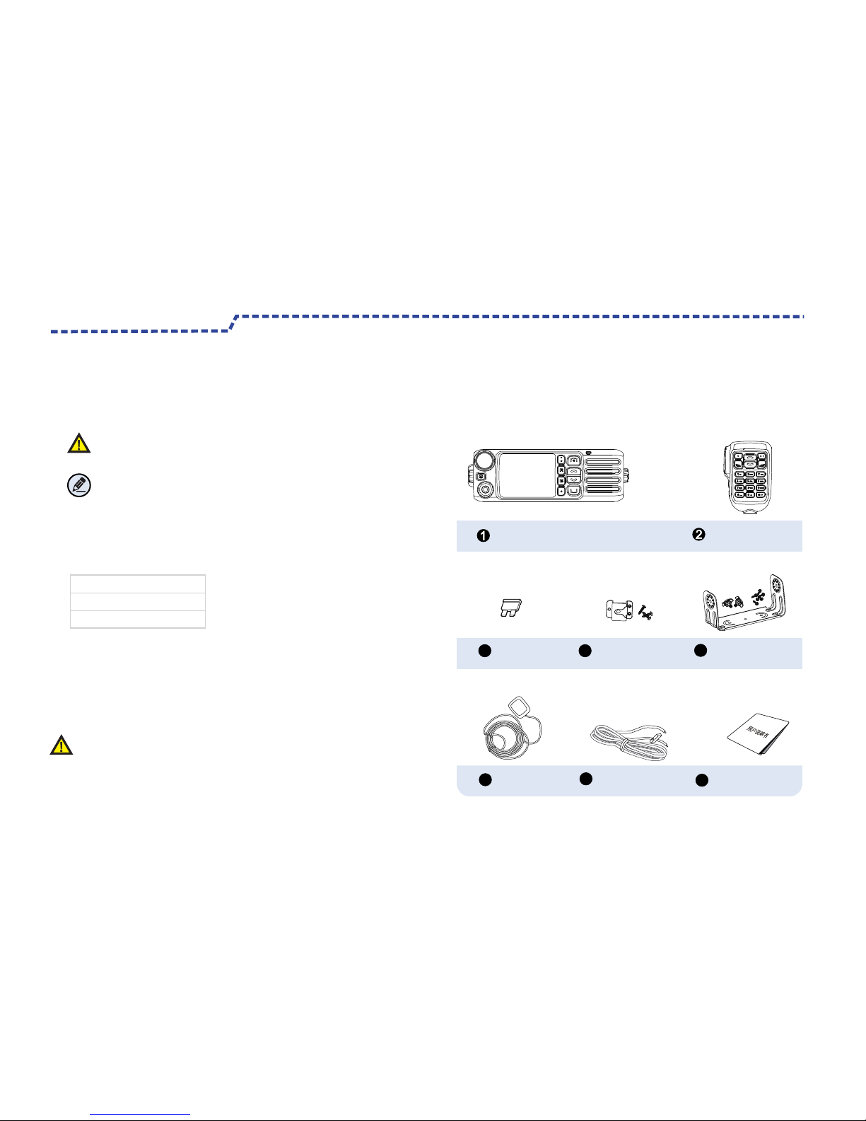
Caution! Packing ListImportant Information Please unpack carefully and check that all items listed below are received.If any item is missing or damaged ,please contact your dealer. Please read this manual carefully before use.Disabled Frequency 360.670MHz364.800MHz384.000MHzCaution:Indicates situations that could cause body injury or damage to your products.Alert IconsNote Indicates tips that can help you make better use of your products.Restricted to occupational use to satisfy FCC RF exposure limits. Radio Palm Microphone Fuse Mounting Bracket Kits GPS Antenna Power Cord User Manual345678Microphone Hanger and Screws
8

Before Use1.Install the bracket on both sides of Radio with screws and lock knobs.2.Plug the palm microphone into radio assigned Plam Microphone Conector.3.Plug the antenna into the back of radioassigned connector. 4.Plug the GPS antenna into the back of radio assigned connector.5.Plug the power cable into the Power Inlet .123456897No.Parts Name 12345Power BoxPalm Microphone Jack GPS Antenna6789Installation Schematic Drawing: 1010FuseLocking KnobBracketScrewsRadio AntennaPower Inlet 9
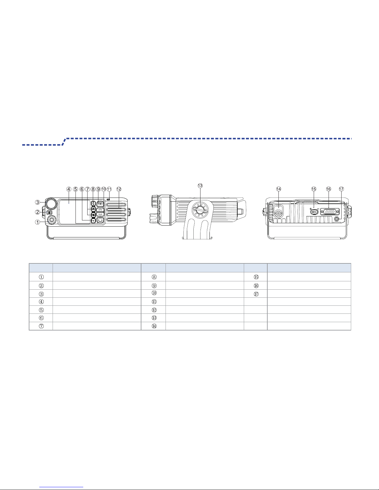
Before Use 10Products Control No.Microphone ConnetorVolume Control/Channel Selector KnobP3 Key/Called Key/Calling Key P1,P2 KeyP4 Key/Hangup Key/Home Key LED IndicatorBracket Knob Power InletAPI ConnectorGPS Antenna TK Key LCD Display Menu Key Setting Key Up/Down Key SpeakerAntennaPart NameNo.Part NameNo.Part Name

Before Use 11 Hangup Key/Home Key【P4】Up/Down KeyTK Key Microphone Fixed BracketPTT Key Microphone Fixed Button P1 Key P2 KeyMenu KeyNumeral Key Microphone Called/Calling Key【P3】Setting KeyMicrophone Control Part NameNo.No.Part NameNo.Part Name

LED Indicator Radio Status LED flashes green slowly.Standby(no load) LED flashes green rapidly.Upgrading or powering on LED glows green. Receiving Transmitting LED flashes orange slowly. Scanning
After voice communication ends,you can hold down the PTT key to talk while the LED is glowing orange.
Status Icon Icon Icon Name Signal Strength Icon New Message Icon ,Inbox Icon is full Scan Icon High Power Icon Low Power Icon Accessory Icon Roam Icon GPS Icon Missed Call Icon LED IndicatorBefore Use LED flashes red rapidly. LED glows red. LED flashes orange rapidly. LED glows orange. MMMMiddle Power Icon ReservingReserving 12
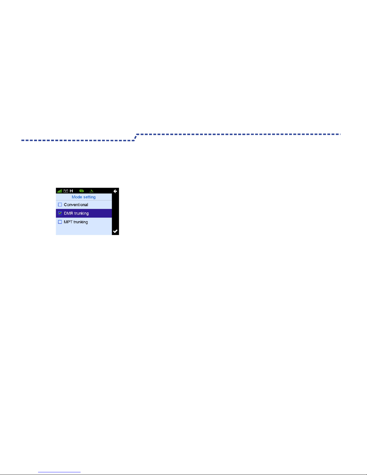
Operation Mode This radio supports three operation Mode :DMR Trunking mode,MPT Trunking mode and Conventional mode(Digital and Analog).Switching Methods:
Product Information Display Alert TonePress the Setting Key to access “Function Setting”- “Mode Setting” and select a appropriate mode.Note:To access Digital Conventional Mode and Analog Conventional Mode to select Conventional Mode. Time and Date Display SettingYou may achieve the following product information in this interface : Radio Alias,Radio ID,Series Number, Model Name ,Model Number,Frequency Range, Radio Versions,Data Base Versions,Vocoder Versions, Latest Programming Date and ESN Code and so on.Press Setting Key to access Product Information interface and review all the information.Use this function to modify this radio Date and Time.Press “Setting”Key to access “Radio Setting”-“Date and Time”interface to modify the Date and Time.This function enable you set the following tones for your radio:“Keypad Tone”, “Calling Tone”,“Called Tone”,“Function Tone”,“Warning Tone”,“Low Battery Tone”and “Message Tone” Press Setting Key to access “Radio Setting”-“Tone”.Note: The function tone is the alert tone of the programmable Key function On/Off and Switching ,such as High or Low power Switching and Zone Switching.BacklightTo set the backlight parameters of On/Off time,Off Type and Brightness Value.Press Setting key to access “Radio Setting”-“Display Setting” .Product Function and Operations This radio supports Menu Reset function ,that is ,if you don’t operate the menu for a predefined time period. This radio will automatically back to the home screen.Hold down the Setting Key ,go to the “Product Setting” -“Menu Reset”Menu Reset 13

High Noise ReductionThis function will effective reduce the noise under the high noise conduction.The noise reduction reach 25dB and makes voice will be clear.This function are available for your setting through the Programmable key and radio Menu. Note: This feature default off .If this feature is enabled , your speaking volume will be low. After this feature is enabled,you need speak near the MIC. Time- out Timer(TOT)The purpose of TOT is to prevent any user from occupying a channel for an extended period.You can set the longest time of single pressing PTT.If the preset time expires ,the radio will terminate transmission automatically .This feature can be enabled via the programming softwareSetting.GPS PositioningYou are available to set the keys P1,P2,P3,P4,Up,Downand TK key as the shortcuts,such as High Power and Low Power switching and Zone Up and Zone Down, Squelch and Scan .This function only via the programming software setting. This function helps to get and upload the radio GPS positioning data(As shown).Press Setting Key ,to go to "Radio Information”-"Positioning System”- “Positioning System On/Off”to turn On/Off GPS function. After GPS turn on,the radio status Positioningicon will display.If the GPS locate successfully ,the icon change to from .Review the GPS Positioning data from the “Radio information”- “Positioning System”- “Radio Positioning Information”. Programming Key Product Functions and Operations 14

Transmitting a call through Contacts List or Call Logs1.Press Menu Key to go to main Menu. 2. Go to“Contacts List - Private Call Contacts”,or go to "Call Logs" and access the outgoing /Incoming/Missed list.3. Use the Up/Down Key to select the Private Call Contacts you want to call.4. Use P3 Key or PTT Key to transmitting a call. Private CallUnder DMR trunking mode, to set Private Call type via trunking system. FOACSU and OACSU ●FOACSU: While seting up a call,ring warn the calling party, and the called party receive the call through manual operation. ●OACSU : While seting up a call without any ring warn for the calling party ,and the called party receive the call automatically.Transmitting a Private CallNote:To ensure an optimal volume of the receiving radio,hold the radio approximately 2.5 to 5cm from your mouth.You may transmit a Private Call through any of the following methods.Through microphone manual input1.Input a Private Call number you want to call in home screen .2. Use P3 Key ,PTT Key or select Dail Key # to transmitting a Private Call.Transmitting a call through Redail List or Recall List.1.Use P3 Key to Redail List or P4 Key to Recall List to input a Private Call number you want to call in home screen .2. Use P3 Key or PTT Key to transmitting a Private Call.Note:Transmitting a Private Call Failed while products unregistered or Registration failed .Product Functions and Operations 15
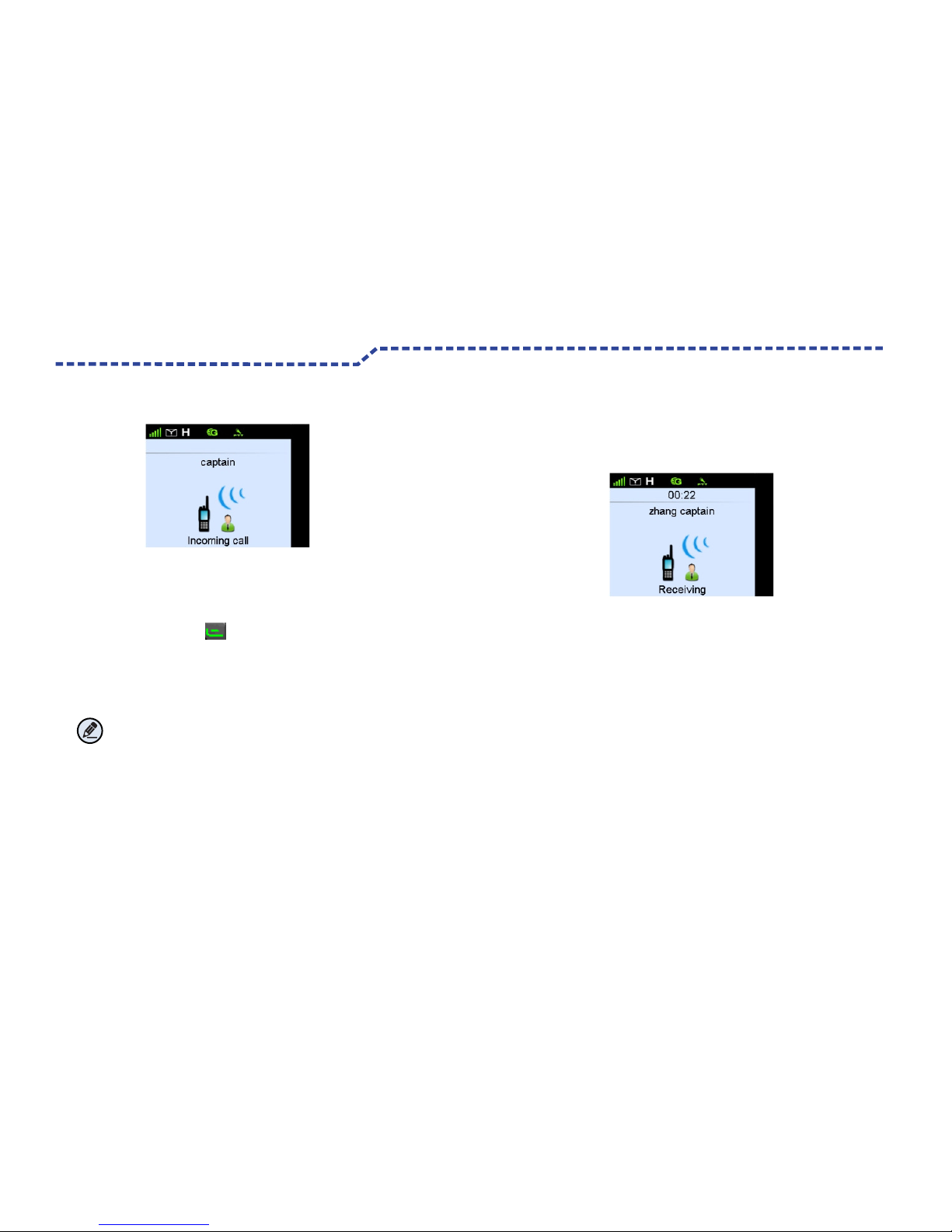
Call DurationReceiving and Responding to a Private CallWhen a Private Call is received ,your radio automatic to receive a Private Call and sounds “De,De”,your radio will display the icon(As shown above) .You may press P3 key or PTT key, the incoming call ring and icon will disappear ,the first line display the incoming call alias or ID.(As shown above) Note:No need press the Receiving Key while setting automatic receiving and responding to a Private Call .After setting up a Private Call ,Both the calling party and called party LCD will display call duration in time .Unit is “Minutes :Seconds”. (As shown below)● The calling party LCD .To count up the Call Duration by count -down,the starting time of count-down time is the total lasted talking time.This time is preset time via system configuration .When the total lasted calling time expires the preset time,this radio will return back from calling and end this call.● The called party LCD To count up the Call duration time by occurred time ,the start time from 0.Voice Communication After setting up a private Call ,Both the calling party andcalled party are in PPT allowed interface ,and hold down PTT to talk.Ending a Call1.Nobody hold down PTT Key for a long time ,and this radio will end call automatically when silence period expires.2.This radio will end call when the total calling time expires the preset time.3.During calling, any party of calling or called hang up.4.Base station signal lost.Product Functions and Operations 16

Ending a Call1.Nobody hold down PTT Key for a long time ,and this radio will end call automatically when silence period expires.2.This radio will end call when the total calling time expires the preset time.3.During calling, any party of calling or called hang up.4.Base station signal lost. Product Functions and Operations Current Channel Display● Display radio channel After initiating a call application ,LCD will display master control channel of radio registered base station before setting up voice communication.● Display operation channel After setting up a call, LCD will display the operation channel of the current base station occupied. 17

Receiving and Responding to a Group CallGroup CallYou may transmitting a Group Call through any of the following methods.Transmitting a call to the preset contacts.In the home screen,hold down PTT Key to transmitting a Group Call to the Group Call Contacts preset for the current Channel.(By the Group Knob to select a group you want to call).1. Press Menu Key to Main Menu 2. Go to“Contracts List--Group Call Contacts ”or “Call Logs” to access outgoing/Incoming /Missed Call.3. Use the Up/Down Key to select the Group Call contacts you want to call.4. Use P3 Key or PTT Key to transmitting a Group Call.1.Input a Group Call number you want to call.2. Use PTT Key, P3 Key or Dail Keypad # to transmitting a Group Call. 1. Use P3 key ,to go to Call Logs List or press P4 Key to select group call number you want to call.2. Use P3 key or PTT Key to transmitting a Group Call.Voice CallAfter seting up a call ,Hold down PTT key to initiate a call when the calling party and the called party are in the PTT Allowed interface.When a Group Call is received, your radio will display the icon and have a "De"alertting tone.Press P3 or PTT Key,the incoming call iron will disappear . Late Access Before Group Call set up to the ended, those following type radios will join in this haven’t ended Group Call such as :Raio just powering on , Radio just roams from other base station or radio just releases from other group .DMR Functions and Operations Transmitting a group call to the contacts List or Call Logs.Transmitting a Group Call through manual inputTransmitting a call through recall List or Call Logs 18

Call DurationAfter setting up a Group Call ,Both the calling party LCD and the called party LCD will display Call Duration in time .Unit is “Minutes :Seconds.”(As shown below) ● The calling party LCD .To count up the Call Duration by count -down,the starting time of count-down time is the total lasted talking time.This time is preset time via system configuration .When the total lasted calling time expires the preset time ,this radio will return back from calling and end this call.● The called party LCD To count up the Call duration time by occurred time ,the start time from 0.To count up from the called party access to Group Call .Recount up by count-down requires when the called party end a Group Call and access this group by “Late Access”.DMR Functions and Operations Group Call Calling Party ID or Alias DisplayAfter initiating a Group Call, all parties LCD will display the Group Call calling party ID or alias. Communication Channel Display ● Display master control channel After initiating a call application ,LCD will display master control channel of radio registered base station before setting up voice communication. ● Display main operation channel After setting up a call,LCD will display the operation channel of the current base station occupied. 19
Table of contents
Other Excera Radio manuals


