У/Ш Ш //А GENERAL USE м ш /ш /л
Phase locked-loop Circuit (PLL)
The PLL circuit consists essentially of:
- the voltage controlled oscillator (VCO) by the transistors Q403, Q402 and Q401
- the charge pu p circuit Q405, Q406
- the integrated circuit IC401 which contains the reference frequency, the progra able generated fre-
quency divider and the phase co parator.
The information necessary for the working of the integrated circuit is sent in sériés by the micro Controller
IC701.
The output signal of this oscillator is the frequency 38,100 MHz for channel 40 in é ission ode.
The frequency différence between the two odes (réception and é ission) is obtained by switching the coil
L403.
EMITTER:
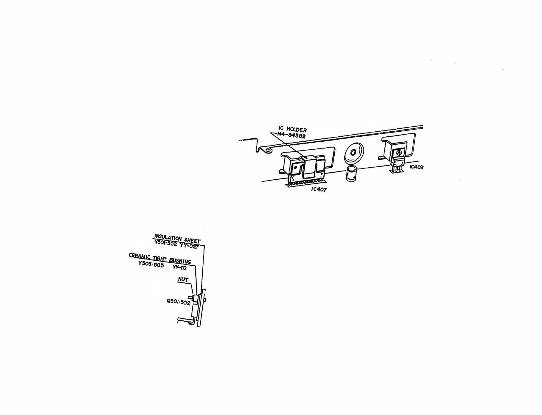
In AM the low frequency signal is prea plified by IC605, then a plified by IC201 and enters into the
odulation transfor er T201. This a plified low frequency signal is applied to the high frequency power
supply stage Q502, Q501 by their collecter so that the high frequency is odulated.
In FM the low frequency signal is li ited and filternd by the stage IC606, D604 is applied to the diode Varicap
D406 via the adjustable résistance VR400.
The signal delivered by the frequency odulated VCO by this low frequency signal, will be applied to the
power supply stage which consists of the transistors Q201, Q502 et Q501.
In AM/FM, the a plified signal will be filtered before being sent to the antenna socket JK425.
RECEIVER:
The VCO signal is used as a first local oscillator. The ixing with the received frequency is carried out by
the stage L7, D7, L8 which gives a first I.F. of 10,695 MHz. The signal reference of the PLL at 10,240 MHz
is used as a second local oscillator by Q12 to obtain a second I.F. at 455 KHz.
In AM, the latter will be applied to the AM détecter stage, co posed of D12, and co anded by Q17.
In FM, the latter will be applied to the FM détecter stage, co posed of the integrated circuit IC1 (discri inator)
and its loading coil L21.
In AM/FM, the low frequency signal is then applied to the transistor Q21, low frequency prea plifier and then
to the low frequency a plifier IC 407 via the volu e Potentio eter.