EXCISION PGM 280 User manual

PGM 280
OPERATION MANUAL

2
MACHINE CERTIFICATION AND
IDENTIFICATION MARKING
NOTE : This manual is a part of the machine and must accompany it if moved
within the company or sold.
ATTENTION !!!
BEFORE USING THE MACHINE, PLEASE READ THIS MANUAL
CAREFULLY. ALL EXPLANATIONS, INSTRUCTIONS AND
WARNINGS ARE INTENDED TO PROTECT YOU!

3
WARRANTY CONDITIONS
The machine is under the warranty of Excision Pty Ptd. For a period of 2 years for mechanical
parts, 1 year for electric and electronic parts from the date of purchase. This warranty is subject to
all of the terms and conditions listed below:
1. This warranty is valid only if the Warranty Registration Form is filled in and returned to
the manufacturer or its authorized dealer within two months after the date of purchase.
2. The obligation of the manufacturer under this warranty shall be limited to repairing or
replacing components which proves defective and which our examination shall disclose to
our satisfaction to be defective.
3. Defects due to improper operation, misuse, neglect, alteration, irregular voltage conditions,
inadequate wiring, improper installation (all electrical and electronic components, all
electrical motors etc.) and due to accidents or any damage caused by transportation, flood,
fire, natural disasters, theft are not included in this warranty and are strictly the
responsibility of the purchaser.
4. Any part returned to Excision or its authorized dealer under the terms of this warranty shall
be on the basis of transportation charges prepaid by the customer and must be
accompanied by a record of the machine model code and serial number.
5. This warranty does not apply to the following components; band saw blade, blade pressure
pads or brackets and blade guide bearings because of being consumables.
6. Manufacturer and authorized dealer cannot be blamed within maximum repair period for
the material or moral damage. Apart from that act the period as Warranty Conditions and
there will not be done any retroactive requirement.
Excision Pty Ltd
Dealer:

4
Important!
This form must be duly completed and returned to the manufacturer or its authorized dealer within
two months after the date of purchase. Failure to do so will void the warranty.
Return Address:
Excision
PO Box 807 Hamilton VIC 3300
WARRANTY REGISTRATION FORM
Machine Model : …………………………………………………………
Serial Number : …………………………………………………………
Invoice Date : …………………………………………………………
Invoice Number : …………………………………………………………
Dealer:
…………………………
Customer:
…………………………

5
CONTENTS
1 SAFETY...................................................................7
1.1.SAFETY RULES ..............................................7
1.2.DANGER ZONE ON THE MACHINE............7
1.3.SAFETY EQUIPMENTS AND
ASSIGNMENTS .....................................................8
1.3.1.BREAK-OFF SWITCH .............................8
1.3.2.COVER SWITCH......................................8
1.3.3.DOWN LIMIT SWITCH ...........................8
1.3.4.EMERGENCY STOP BUTTON ...............8
1.4.WARNING LABEL AND ASSIGMENTS.......8
1.4.1.GLOVE LABEL ........................................8
1.4.2.ELECTRICITY NEUTRAL WARNING
LABEL................................................................8
1.4.3.HIGH VOLTAGE LABEL ........................8
1.4.4.SAFETY EQUIPMENTS LABEL.............8
1.4.5.ARROW LABEL.......................................8
2 DESCRIPTION AND PROPERTIES...................9
2.1 TECHNICAL PROPERTIES OF THE
MACHINE ..............................................................9
2.2 STANDARD EQUIPMENTS ...........................9
2.3 NOISE LEVEL..................................................9
2.4 MACHINE DIMENSION .................................9
2.5 MACHINE CUTTING CAPACITY .................9
2.6 PROPERTIES TABLE ACCORDING TO
METAL SAWDUST...............................................9
3 TRASPORTATION AND INSTALLATION.....10
3.1.HANDLING THE UNPACKED MACHINE .10
3.2.AFTER UNPACKING THE MACHINE........10
3.3.ENVIRONMENTAL CONDITIONS .............10
3.4.MACHINE PLACEMENT AND POSITION.10
4 PREPARATION BEFORE OPERATION.........10
4.1.CLEANING.....................................................10
4.2.LUBRICATING..............................................10
4.3.COOLANT......................................................10
4.4.ELECTRICAL POWER CONNECTION.......10
4.5.FINAL INSPECTION CHECKLIST BEFORE
OPERATION.........................................................11
5 OPERATION........................................................ 11
5.1. CONTROL PANEL ....................................... 11
5.2.BLADE CHANGING PROCEDURE............. 11
6 MAINTENANCE.................................................. 13
6.1.DAILY MAINTENANCE .............................. 13
6.2.WEEKLY MAINTENANCE.......................... 13
6.3.MONTHLY MAINTENANCE....................... 13
6.4.SIX-MONTHLY MAINTENANCE ............... 13
6.5.PERIODIC MAINTENANCE ........................ 13
7 TROUBLESHOOTING ...................................... 14
8 DISMANTLING ................................................... 15
9 SPARE PART LIST ............................................. 16
9.1.MACHINE BASE ASSEMBLY..................... 17
1.3.1.MACHINE BASE UPPER FRAME ........ 18
9.2.FLANGE JOINT ASSEMBLY....................... 19
9.3.CLAMP ASSEMBLY..................................... 20
9.4.BOW ASSEMBLY ......................................... 21
9.5.GEARBOX ASSEMBLY ............................... 22
9.6.BLADE TENSIONING ASSEMBLY ............ 23
9.7.BOW LIFT CYLINDER ASSEMBLY........... 24
9.8.BLADE GUIDE ASSEMBLY........................ 25
9.9.MOBILE BLADE GUIDE COMPLETE........ 25
9.10.FIXED BLADE GUIDE COMPLETE.......... 26
9.11.SPRING ASSEMBLY................................... 27
10 CONTROL CIRCUIT DIAGRAM................... 28
11 POWER CIRCUIT DIAGRAM........................ 29

6
1SAFETY
1.1 . Safety Rules
Never allow unqualified persons to
operate or interfere with the machine
It is important to develop personal safety
awareness. Observe all related safety
regulations and pay attention for
hazardous conditions. Discuss these
conditions with your supervisor.
You must use personal protective
equipment, like safety glasses, gloves,
safety work shoes.
Do not remove warning signs and/or
instruction plates off the machine.
Make sure that all machine controls are
set for the desired mode of operation,
whenever the setting of the machine
control is changed, run the machine in
slow mode to make sure it operates as
expected.
Never disable any safety device to avoid
its assigned function. These devices are
intended to protect both the machine and
its operator.
Do not load, unload, operate or adjust the
machine without proper instructions.
This machine is specifically designed for
cutting general metal material. Do not cut
wood and analogous material, meat,
fishery, food and agriculture products,
combustible and radioactive materials.
Enough space should be provided around
the machine to avoid hitting and provide a
convenient operation.
Do not leave any tool on the machine after
use. Do not put work stock or tools
around the machine, to avoid injury.
Do not operate the machine with its safety
guards removed.
Do not wear gloves when operating
through control panel.
Wear gloves only when
loading/unloading the material, changing
the blade and chip brush.
Never touch the blade, moving work stock,
nor put your hands into the vise area or
chip conveyor unit until the machine halts
completely.
When selecting blade, blade speed and
coolant, please refer to the operation
manual or related documents.
Before installation and operate the
machine check the sufficiency of the earth
of the machine to your electrician. Do not
operate the machine without the earth.
Determined and declared bench life of the
machine by the Ministry of Industry and
Trade is 10 years.
For longevity please follow the
maintenance directions at the manual.
1.2 . Danger Zones on the Machine
Do not open the guards/covers during
operation.
During cutting process keep your
hands and fingers away from running
blade which should on number one.
During cutting process keep away
from zone number two. It may cause
hitting and dropping injury.
Do not Touch electrical panel if you
are not expert on electric
1
2

7
1.3. Safety Equipments and Assignments
1.3.1. Break-off Switch
This switch is used for to stop the machine while
the blade pressure gets smaller than adjusted ones.
The main causes of decrease in pressure are;
dulling, cracking or breaking of blade. Operating
the machine under these conditions endanger the
operator.
1.3.2. Cover Switch
This switch provides to shut down the machine
while the bow cover is open. Running the
machine may cause wounding and serious gashes.
Machine gives aural warning while the cover is
open.
1.3.3. Down Limit Switch
This switch is used to adjust the bow’s nadir to
goes down. Down limit switch is a factory setting.
Please do not tinker with the down limit switch.
1.3.4. Emergency Stop Button
Emergency stop button, places on the operator
control panel- near the main switch, is red button
and you can see it easily. In emergency cases,
press to this button to stop the machine. Machine
does not run while the button is pressed. To rerun
the machine, please turn left and release the
button.
1.4. Warning Signs on the Machine
1.4.1. Glove Label
Please use personal protective
equipment, like glove, during
operation and while changing the
blade.
1.4.2. Electricity Neutral Warning Label
In this label, we
declared the
instructions how
to make the electric connection before installing
machine or after handling the machine.
1.4.3. High Voltage Label
This label shows high voltage risk
parts. All electrical connections
should be done by a qualified
electrician.
1.4.4. Safety Equipments Label
All the safety devices
and guards are
designed to intend to
protect the operator.
Please do not remove these safety guards.
1.4.5. Arrow Label
Blade’s direction of rotation belongs to machine.
Arrow label on the machine
shows blade’s direction of
rotation. Please pay attention on
direction of rotation while
changing blade.
Cover Switch
Break-off
Switch
Down Limit
Switch
8
2DESCRIPTION AND
PROPERTIES
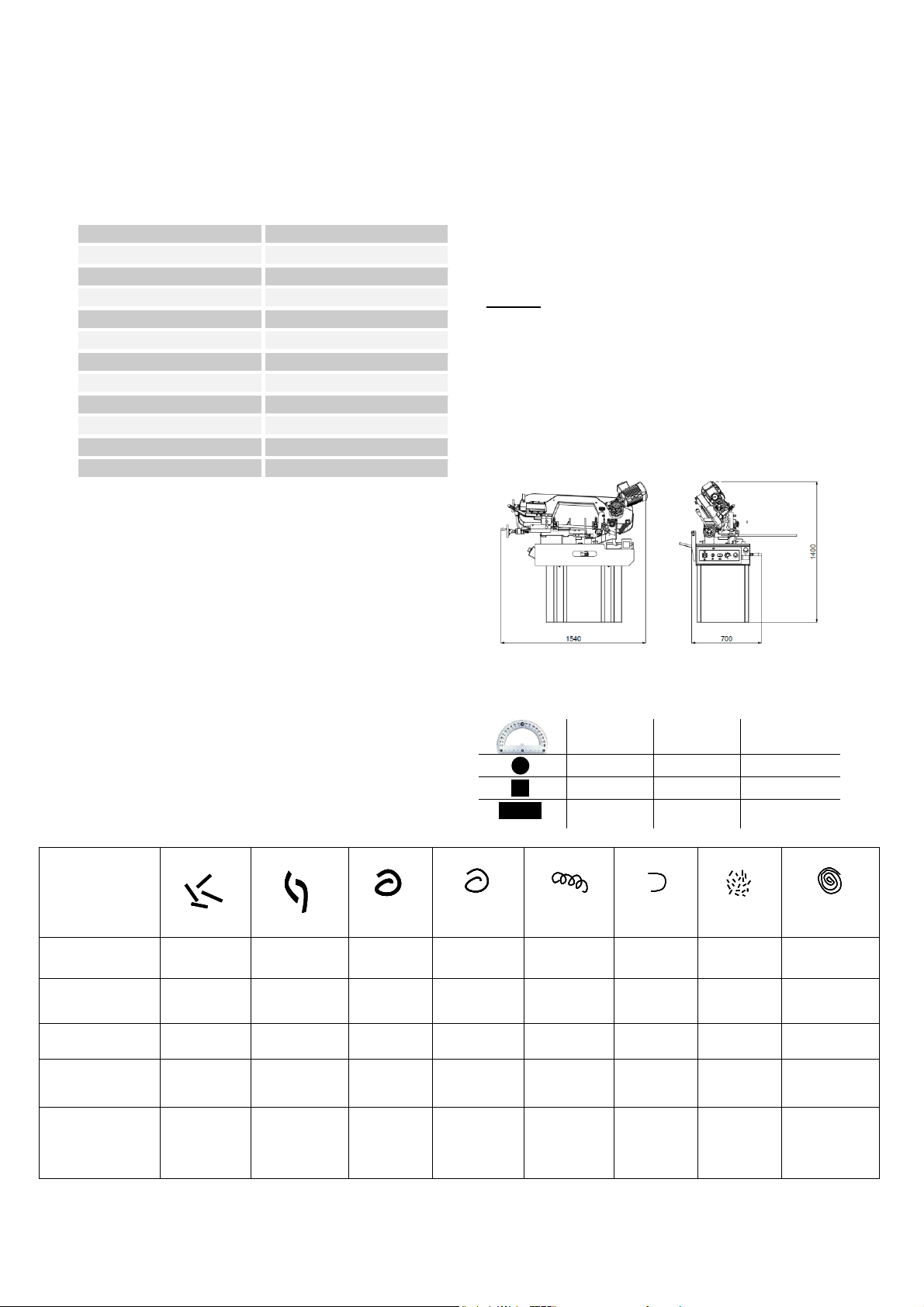
2.1. Technical Properties of the Machine
MAIN MOTOR
1,1 kW, 1400 rpm
COOLANT PUMP
0,09 kW, 2800 rpm
CUTTING SPEED
25-90 m/min
BLADE DIMENSION
2500x27x0,9
BLADE TENSION
Min. 30 bar -Max. 50 bar
BLADE QUALITY
Bi Metal
HEIGHT OF VISE BED
915 mm
WEIGHT
250 Kg.
MACHINE DIMENSION
800 x1560 x 1500 mm
NUMBER OF PHASE
3
FREQUENCY
60 Hz
MAIN VOLTAGE
380V
2.2. Standard Equipment
1 Bandsaw Blade
Hydromechanical Band Tension
Invertor
Adjustable Tension Band Wheel
One way Milter Till 60º
Fast Clamping Arm
Adjustable Length Setting Bar
2.6. Properties Table According to Metal
Sawdust
2.3. Noise Level
In accordance with the Machinery Directive
2006/42/EC
The A-weighted continuous acoustic
pressure does not exceed 70 dB (A).
The maximum level of the C-weighted
instantaneous acoustic pressure is always
less than 130 dB.
NOTE: With the machine operating, the noise
level will vary according to the different materials
being processed and setting up. The user must
therefore assess the intensity and if necessary
provide the operators with the necessary personal
protection.
2.4. Machine Dimensions
2.5. PGM 180 Craft Bandsaw Machine
Cutting Capacity
0°
45°
60°
220 mm
160 mm
95 mm
200 mm
140 mm
75 mm
180 x 250
mm
140 x 150
mm
75 x 95 mm
Filling
Shape of the
Filling
Thick, hard
and short
Thick, hard
and brittle
Thick, hard
and curled
Thick, hard
and curled
Thin, spiral
and curled
Thin, spiral
and curled
Like dust
Thin and
very curled
Colour of the
Filing
Blue or
brown
Blue or
brown
Silver or
yellow
Silver
Silver
Silver
Silver
Silver
Bandsaw Speed
Decrease
Decrease
Suitable
Increase
Suitable
Suitable
Decrease
Suitable
Advance Speed
Decrease
Decrease
Decrease a
little
Decrease
Suitable
Increase
Increase
Decrease
The Others
Control
lubricant
coolant
level
Control
lubricant
coolant level
Control
number of
teeth
Control
number of
teeth
Use thick
pitch saw

9
3TRANSPORTATION AND
INSTALLATION
3.1. Handling the Unpacked Machine
Make sure the machine is safely loaded and
balanced when moving it with a forklift, failing to
do so may cause personal injury or damage to the
machine.
3.2. After Unpacking the Machine
Put the machine in a dry and sheltered place to
prevent damage to the electrical and mechanical
components. Apply appropriate lubricant
(machine oil or grease) on the slide ways and
non-painted areas to prevent rust.
3.3. Environmental Conditions
Mains voltage and frequency complying
with the machine motor characteristics.
Environment temperature from -10° C to
50° C
Relative humidity %10 to %90
3.4. Machine Placement and Position
The followings should be considered when
positioning the machine:
The floor: The machine should be placed on a
lecelled concrete floor.
Working Area: Sufficient space should be
allocated around the machine for comfortably
loading and unloading work stock and for easy
access during maintenance and repair. When
necessary, all doors and access panels should be
opened without interference.
Lighting: The machine and its surroundings
should be well lit for operator’s safety and for a
convenient operation and maintenance.
4 PREPARATION BEFORE
OPERATION
4.1. Cleaning
Unpainted and uncoated machine surfaces were
coated with a rust inhibitor prior to shipment. -
The rust inhibitor should be cleaned with an
appropriate solvent. To prevent rust on unpainted
surfaces, a light coat of machine oil can be
applied.
4.2. Lubricating
Lubricate all the sliding parts before starting.
4.3. Coolant
The machine is shipped with the coolant reservoir
empty. Fill the reservoir with coolant until it is
full. A sight gauge is mounted on the machine
base to check coolant level.
Caution: Do not run the coolant pump without
coolant in the reservoir. Otherwise, the coolant
pump will be damaged.
4.4. Electrical Power Connection
1. Electrical connection must be done by a
qualified electrician, in conformance with the
required electrical standards of your area.
2. Turn off the main circuit breaker of the area in
which the machine will be located.
3. Machine's power cord should be connected to
an appropriate power source; make sure the voltage
rate matches the one required for the machine.
4. It is important that the shipping brace should
be removed from the saw before taking any further
step.
Note: If the ‘emergency stop button’ is
depressed, it must be released for the machine to
run.
10
4.5. Final Inspection Checklist before
Operation
After installing the machine, a final inspection
should be performed by considering the following
checklist;
Any missing components, guards or panels
Removal of the shipping brace
Lost fasteners and fittings, hoses and
conduit
Missing or damaged items
Coolant, oil, or hydraulic leads
Tools and others materials left on saw
Safety measures, general condition and
readiness for use
5 OPERATION
In this section, the functions of the machine will
described to guide the operator to become familiar
with the machine and its components.
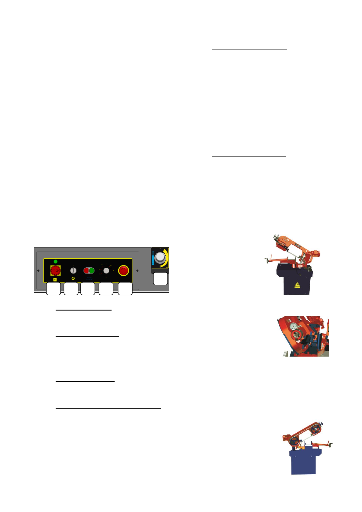
5.1ControlPanel
A) Main Power Switch
The machine is ready when the main power
switch is turned on.
B) Coolant Pump On/Off
Coolant pump switch on/off via this button.
Caution: Do not operate the coolant motor while
coolant tank empty. Otherwise, the coolant motor
will be damaged.
C) Open/Close Switch
Cutting process can be started and stopped with
these buttons.
D) Blade Speed Arrangement Button
Blade speed can be adjusted 25-90 m/min by this
button.
E) Emergency Stop Button
The "Emergency stop" push button stops all
functions of the machine. The machine will not
function until "Emergency stop button’ is
released. To release the emergency button, turn it
in the direction indicated on its hub.
Caution: The "Emergency stop" push button does
not disconnect the machine from the main power
supply. To avoid from serious injury or death due
to electricity shock, turn the main power switch off
or disconnect the machine from the main supply
before servicing it.
F) Bow Down Speed Valve
Bow down speed can be adjusted by this button.
5.2. Blade Changing Procedure
In order to achieve accurate and efficient cuts, it
is important to use a sharp and correct blade for
the material being cut.
1- Raise the saw frame to its highest
position.
2- Turn the hand-wheel to left to loosen the
blade.
3- Switch off the main power switch of the
machine.
Caution: Avoid serious injury by turning the
machine's power off at the main switch before
adjusting, servicing, or cleaning the saw.
4- Open all the wheel covers on the saw
frame.
A
B
C
D
E
F

11
5- Loosen the bolts on the carbide blade
guides. Lower the blade from bandsaw
guides.
6- Lower the chip brush away from the blade
by loosening the chip brush locking lever.
Caution: Wear heavy protective work gloves and
safety glasses when handling blades to avoid
injury.
7- Carefully remove the blade from the saw.
8- Uncoil the new blade and insert the blade
around the band wheels.
Warning: New blades are generally shipped in a
coiled from. This puts them under tension and can
suddenly be uncoiled. Take extreme caution to
revent injury when uncoiling the new blade. Make
sure you wear safety gloves and glasses. Locate
back of edge the blade into the carbide inserts
(pressure pads) and guide bearings so the teeth
point in downward direction.
9- Press the back edge of the blade firmly
against the back-up of the carbide guides
10- Turn on the main switch of the machine.
11- Turn the hand-wheel to right (to
tensioning position) to apply a light
pressure.
12- Press the back edge of the blade firmly
against the flange of each band wheel.
13- Turn the hand-wheel to right (tensioning
position) to exert sufficient tension on the
saw blade.
14- Turn off the main switch of the machine.
15- Turn the bolts clockwise to tighten the
carbide pressure pads against the blade.
Tighten the carbide guides by hand only.
Note: Do not over-tighten the carbide pressure
guides.
16- Adjust the position of the chip brush so
that the bristles reach fully into the gullet
of the blade without extending beyond.
Then lock the chip brush in place.
Important: Improper positioning of the chip
brush will result in excessive blade or chip
brush wear.
17- Make sure that you close and secure the
band wheel covers and blade guards at the
end of this process.

12
6 MAINTENANCE
The maintenance schedule is listed below on the
basis of daily, weekly, monthly and six-monthly
intervals. Utmost care should be given to the
maintenance. Poor maintenance or neglecting
some of its requirements will result in premature
machine failure and/or unsatisfactory
performance.
6.1.Daily Maintenance
Clean/empty the chip reservoir whenever
necessary.
Use suitable brush with soft bristles. Do
not use hard materials to clean the
machine.
Check whether the emergency stop button
functions properly. Check that the entire
wheel covers other safety guards are in
place and fixed properly.
Check the wear on the teeth of the saw
blade.
Check the level of coolant.
Don not use pressured air for cleaning the
machine; expect for unblocking the
coolant pipes.
6.2.Weekly Maintenance
Clean the wheels, vise, slides and
bearings.
Pull the movable jaws of the vise back
and clean the slides, beds and other
moving components and lubricate with
thin grease.
Apply grease to the main vise roller drive
mechanisms gearbox and vise roller
bearings. Check the condition of these
mechanisms and clean them if necessary
before applying grease. Use EP type
grease for vise roller drive mechanisms
gearbox.
Test the quality/condition of the coolant
and water/boron oil ratio; if necessary
renew it.
Non-painted parts should be wiped with a
clean cloth and oiled with protective
machine oil to prevent rust.
Coolant thank should be cleaned against
chips to prevent them accumulating onto
the floor of the tank.
6.3.Monthly Maintenance
Check the level of hydraulic oil from the
site gauge. If the level drops below
indicated min. line, add hydraulic
system oil of grade 46.
Check the conditions of saw blade guide
bearings and carbide pressure pads at the
ends of guide arms. They should be
replaced when they become worn or
loose.
Check the gaps in the bearings of the
wheels. Replace them if they are won.
Check the condition of hydraulic systems
(cylinder/pistons, pipes/hoses, sealants
and hydraulic couplings.)
6.4.Six-Monthly Maintenance
Perform all monthly maintenance checks
for six-monthly maintenance too. And
replaces those parts of the machine that
do not function as expected or that are
excessively worn.
Check the work stock feeding rollers for
wear and renew them if necessary.
Check the vise roller drive mechanisms
gearbox; renew the worn gear wheels if
necessary.
6.5.Periodic Maintenance
Renew the wheel bearings.
Renew the carbide pressure pads and the
saw blade guide bearings.
Check the viscosity/condition of the
hydraulic oil. Renew if it is necessary.
Check the worn/damaged/malfunctioning
components that do not function properly.

13
7 TROUBLESHOOTING
Some of the generally faced troubles and their possible causes and/or remedies are presented in the
following table.
PROBLEMS/FAULTS
POSSIBLE CAUSES AND REMEDIES
Non-straight cuts
Insufficient blade tension
Incorrect or loose work stock clamping
Use coarser blade pitch
High feed rate or pressure
Tooth set damage
Guide arms are loose or set too far apart
Premature blade
breakage, premature
tooth wear and
chipped tooth
Feed rate too high or too low
Check your coolant
Check/adjust carbide blade pressure pads
Check wheel alignment
Allow enough clearance before starting cut
Reduce band tension when the machine isn’t
operated
Cutting speed too high
Wrong tooth pitch
Incorrect or loose work stock clamping
Ineffective coolant application
Improper break-in period
Perform scheduled maintenance
Despite taking all necessary action, if a fault persists, you should call the service

14
8 DISMANTLING
If the machine is to be scrapped;
1. Qualified personnel should carry out all dismantling process.
2. Switch the machine off and disconnect the power supply.
3. Drain the hydraulic oil and coolant.
4. Revert the preceding setting procedure for dismantling the machine.
5. Separate the material to be disposed of depending on their types and composition and have
them collected and/or recycled by waste disposal sevices.
ORDERING SPARE PARTS
When ordering spare parts, you must state;
MACHINE MODEL :
SERIAL NUMBER :
PART REFERENCE NUMBER :
PART NAME :
Without these references we will not supply the spare parts.
16
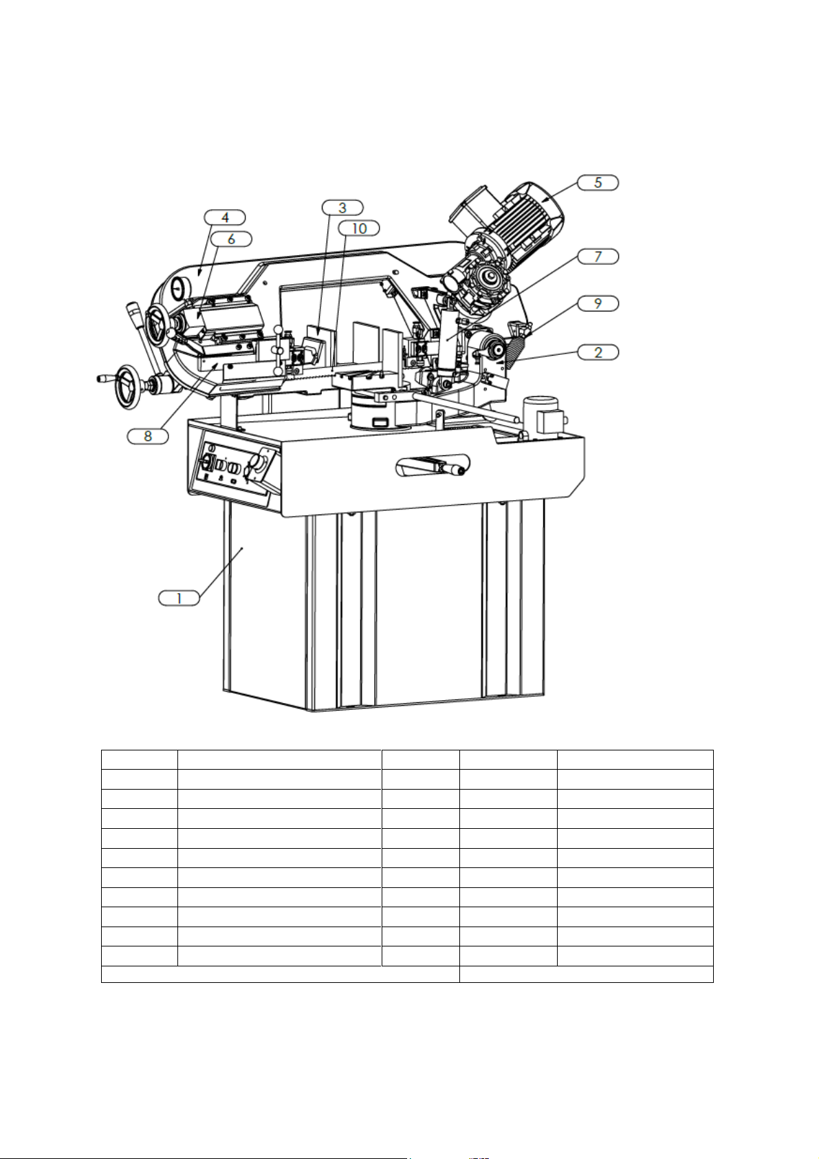
9 SPARE PART LIST
Part No
Part Name
Q.ty
Description
Part Code
10
Band Saw
1
153 03 2010
09
Spring Assembly
1
151 02 16 000
08
Blade Guide Assembly
1
151 02 15 000
07
Bow Lif Cylinder Assembly
1
151 02 12 100
06
Blade Tensioning Assembly
1
151 02 11 000
05
Gearbox Assembly
1
151 02 08 000
04
Bow Assembly
1
151 02 04 000
03
Clamp Assembly
1
151 02 01 620
02
Flange Joint Assembly
1
151 02 23 001
01
Machine Base Assembly
1
151 02 01 002
PART NAME: KMT 220 CRAFT
PART CODE: 154 03 107
17
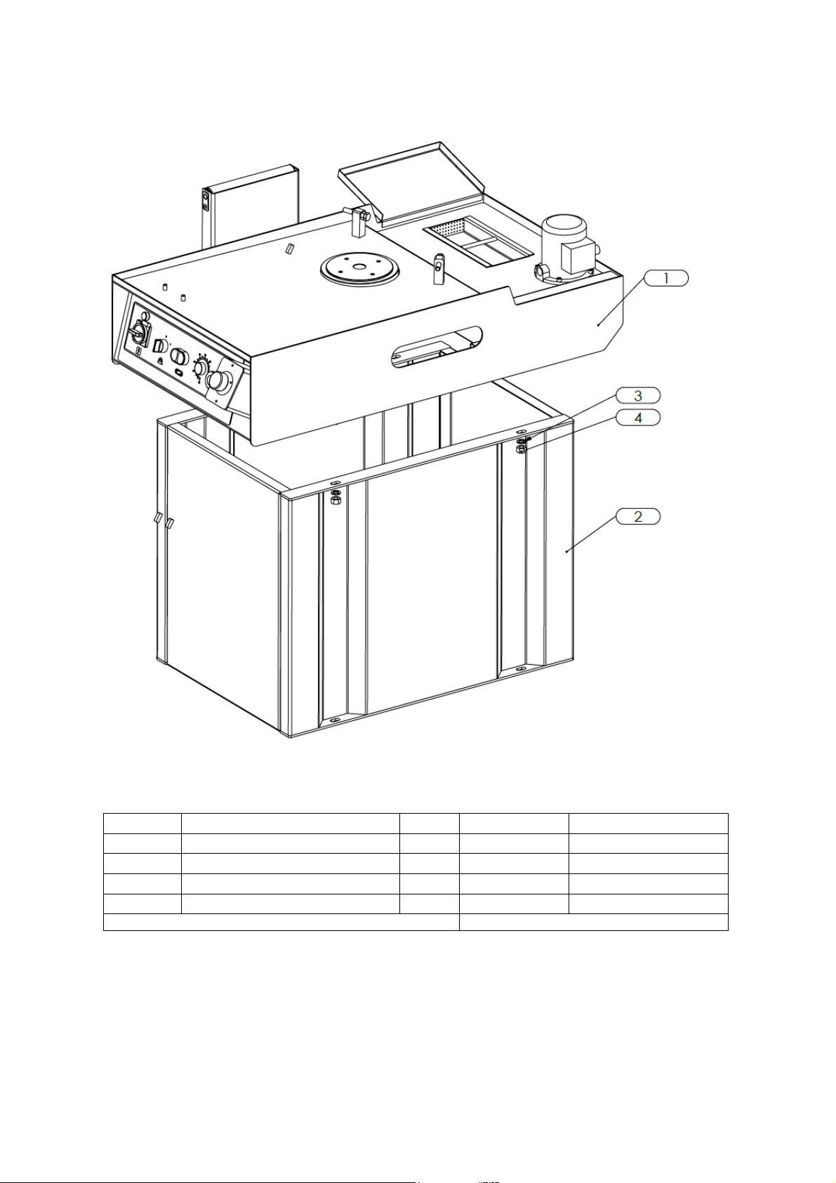
9.1. MACHINE BASE ASSEMBLY
Part No
Part Name
Q.ty
Description
Part Code
04
Nut
4
150 06 375
03
Shim
4
150 06 235
02
Machine Base Lower Group
1
151 02 01 201
01
Machine Base Upper Group
1
151 02 01 700
PART NAME: MACHINE BASE ASSEMBLY
PART CODE: 151 02 01 002

18
9.1.1. MACHINE BASE UPPER GROUP
Part No
Part Name
Q.ty
Description
Part Code
13
Coolant Cover Plate Complete
1
151 02 01 190
12
Roller Group
1
151 02 01 300
11
Bolt
4
150 06 241
10
Nut
2
150 06 317
09
Bolt
2
150 06 1328
08
Coolant Pump
1
150 02 017
07
Swarf Hamper
1
151 02 01 180
06
Bolt
4
150 06 020
05
Pressure Arm Flange
1
151 02 06 667
04
Cylinder Throttle Valve
1
151 02 12 121
03
Upper Shimmer
1
151 02 01 615
02
Drawer Group
1
151 02 01 611
01
Base Upper Frame
1
151 02 01 600
PART NAME: MACHINE BASE UPPER GROUP
PART CODE: 151 02 01 700

19
9.2. FLANGE JOINT ASSEMBLY
Part No
Part Name
Q.ty
Description
Part Code
05
Spring Connection Plate
1
151 02 23 112
04
Angle Indicator
1
151 02 23 092
03
Stay Bolt
1
150 06 168
02
Bolt
2
150 06 200
01
Flange Joınt Moulding
1
151 02 23 101
PART NAME: FLANGE JOINT ASSEMBLY
PART CODE: 151 02 23 001
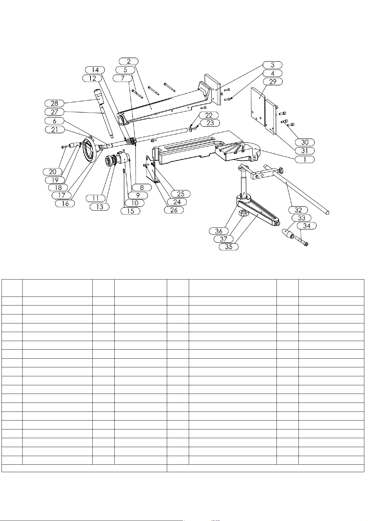
20
9.3. CLAMP ASSEMBLY
Part
No
Part Name
Q.ty
Part Code
Part
No
Part Name
Q.ty
Part Code
19
Bakalite Knob
1
150 06 1365
18
Nut
1
150 06 293
37
Nut
1
151 02 06 666
17
Plastic Wheel
1
151 02 11 111
36
Mile
1
151 02 06 670
16
Nut
2
150 06 828
35
Pressure Arm
1
151 02 06 685
15
Stay Bolt
2
150 06 253
34
Bolt
1
150 06 405
14
Bearing
1
150 06 398
33
Bakalite Knob
1
150 06 1364
13
Bearing
1
150 06 1273
32
Lenght Adjustment Group
1
151 02 06 200
12
Vise Pressure Spring
1
151 02 06 308
31
Fixed Right Jaw
1
151 02 06 106
11
Bearing Cover
1
151 02 06 309
30
Bolt
5
150 06 201
10
Vise Pressure Arm
1
151 02 06 307
29
Fixed Left Jaw
1
151 02 06 105
09
Bearing Bush
1
151 02 06 306
28
Bakalite Nut
1
150 06 1331
08
Pin
1
150 06 094
27
Vise Pressure Mile
1
151 02 06 320
07
Spring Shim
1
151 02 06 305
26
Bolt
2
150 06 241
06
Clamp Shaft
1
151 02 06 304
25
Shim
2
150 06 055
05
Bolt
3
150 06 1303
24
Fixing Plate
1
151 02 06 310
04
Bolt
4
150 06 1008
23
Bolt
1
150 06 1340
03
Vise Jaw
1
151 02 06 303
22
Clamping Shim
1
151 07 06 340
02
Top Body
1
151 02 06 302
21
Pin
1
150 06 180
01
Clamp Lower Table
1
151 02 06 361
20
Bolt
1
150 06 1365
PART NAME: CLAMP ASSEMBLY
PART CODE: 151 02 01 620
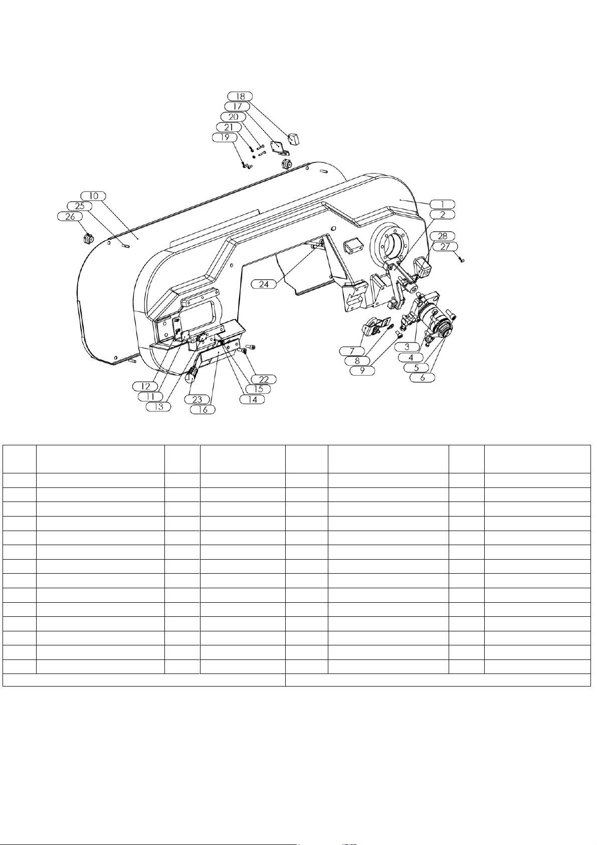
21
9.4. BOW ASSEMBLY
Part
No
Part Name
Q.ty
Part Code
Part
No
Part Name
Q.ty
Part Code
14
Bolt
2
150 06 988
28
Bolt
4
150 06 042
13
Switch
1
150 01 050
27
Stay Bolt
1
150 06 563
12
Bolt
2
150 06 353
26
Nut
4
150 06 380
11
Switch Plate
1
151 02 11 158
25
Stay Bolt
4
150 06 463
10
Cover Complete
1
151 02 04 110
24
Bolt
8
150 06 1327
09
Bolt
1
150 06 948
23
Knob
1
150 06 1440
08
Shim
1
150 06 176
22
Bolt
2
150 06 201
07
Swarf Brush Assembly
1
151 02 04 200
21
Nut
2
150 06 817
06
Bolt
4
150 06 003
20
Bolt
2
150 06 1339
05
Connector Complete
1
151 02 04 105
19
Bolt
2
150 06 336
04
Nut
1
150 06 317
18
Switch
1
150 01 020
03
Body Lift Mile
1
151 02 04 103
17
Cover Switch Plate
1
151 02 04 120
02
Body Lift Part
1
151 02 04 102
16
Lift Arm
1
151 02 04 121
01
Body Part
1
151 02 04 101
15
Nut
2
150 06 814
PART NAME: BOW ASSEMBLY
PART CODE: 151 02 04 000
Table of contents


