Exclusiva BlueStar 55BT M User manual

BlueStar 55BT M
BlueStar 66BT M
BlueStar
Scrubber Dryer
Technical data plate.
PLEASE NOTE:
Before use, carefully read
the instructions.
3
A
3
1
4
8
7
6
2
5
4
B
2
3
56
8
4
9
7
1
10

5
D
C
1
4 5
6
33A 3B 3C 3D
2
A
B
34
5
1
67
89
2
6
F
E
1 2
3
123
7
H
G
I
123
2
1

8
4
3
6
5
4
3
6
2
7
75
1
1
2
1
L
M
N

25
CONTENTS
1. GENERAL INFORMATION
1.1. SCOPE OF THE MANUAL
1.2. TERMINOLOGY AND SYMBOL LEGEND
1.3. PRODUCT IDENTIFICATION
1.4. SPECIFIC USE
1.5. TECHNICAL MODIFICATIONS
2. SAFETY INFORMATION
2.1. BASIC RECOMMENDATIONS
2.2. NOISE AND VIBRATIONS
3. HANDLING INFORMATION
3.1. PACKING LIFTING AND TRANSPORT
3.2. CHECKS UPON DELIVERY
3.3. UNPACKING
3.4. LIFTING AND TRANSPORT: MACHINE,
BATTERY AND BATTERY CHARGER
4. TECHNICAL INFORMATION
4.1. GENERAL DESCRIPTION
4.1.1. MACHINE
4.1.2. BATTERY
4.1.3. BATTERY CHARGER
4.2. STRUCTURE AND FUNCTIONS
4.2.1. MACHINE
4.2.2. BATTERY
4.3. ACCESSORIES
5. INSTALLATION INFORMATION
5.1. BATTERY PREPARATION
5.2. BATTERY INSTALLATION AND PREPARATION
5.2.1. CIRCUIT BOARD SETTINGS CONFIGURATION
5.3. BATTERY CHARGER CONFIGURATION
5.4. MACHINE PREPARATION
6. OPERATING INFORMATION
6.1. BATTERY CHARGING
6.2. SQUEEGEE AND SPLASH GUARD ASSEMBLY,
DISASSEMBLY AND ADJUSTMENT
6.2.1. SQUEEGEE ASSEMBLY
6.2.2. SQUEEGEE DISASSEMBLY
6.2.3. SQUEEGEE BLADES DISASSEMBLY /
ASSEMBLY
6.2.4. SQUEEGEE ADJUSTMENT
6.2.5. SPLASH GUARD ASSEMBLY/ DISASSEMBLY
6.3. BRUSH ASSEMBLY / DISASSEMBLY
6.4. FILLING AND DRAINING THE DETERGENT
SOLUTION TANK
6.5. DRAINING THE RECOVERY TANK
6.6. DRIVING THE MACHINE
6.7. WORK METHOD
6.7.1. PREPARATION AND WARNINGS
6.7.2. OPERATING CONTROLS
6.7.3. DIRECT SCRUBBING OR FOR SLIGHTLY
DIRTY SURFACES
6.7.4. INDIRECT SCRUBBING OR FOR VERY
DIRTY SURFACES
6.7.5. POSTSCRUBBING OPERATIONS
6.8. SPECIFIC INSTRUCTIONS FOR THE USE OF
POWER MAINS AC 230V MODEL
7. MAINTENANCE INFORMATIONS
7.1. TANK S
7.2. SUCTION HOSE
7.3. SQUEEGEE
7.4. ACCESSORIES
7.5. MACHINE BODY
7.6. BAT TER IES
7.7. FUSES AND THERMAL BREAKERS
7.8. PERIODIC MAINTENANCE
7.9. RECOMMENDED SPARE PARTS
8. OPERATING CHECKS
8.1. THE MACHINE DOESN’T WORK
8.2. THE MACHINE DOESN’T MOVE FORWARD
8.3. THE BRUSHES DON’T ROTATE
8.4. NOT ENOUGH OR TOO MUCH DETERGENT
8.5. NO SUCTION
8.6. THE BRUSH MOTOR OR THE SUCTION
MOTOR DOESN’T STOP
8.7. THE SQUEEGEE DOESN’T CLEAN OR DRY
EFFICIENTLY
8.8. THE BATTERY CHARGER DOESN’T WORK
8.9. THE BATTERIES DO NOT CHARGE OR DO
NOT HOLD A CHARGE
9. CONDITIONS OF WARRANTY
9.1. SCRAPPING OF THE MACHINE
9.2. DISPOSAL WEEE

26
1. GENERAL INFORMATION
1.1. SCOPE OF THE MANUAL
To make it easier to read about and look up various
subjects, refer to the table of contents at the begin-
ning of the section in your language.
This manual has been prepared by the manufacturer
and is an integral part of the product. As such, it must
be kept in a safe place for the machine’s entire service
life until demolition.
The customer must ensure that machine operators
have read or are familiar with the contents of this
manual so that they strictly follow the instructions
described herein.
Constant compliance with the instructions provided
in this manual is the only way to guarantee the best
results in terms of safety, performance, efficiency and
service life of the product you now own. Non-com-
pliance with these rules may cause injuries to people
and damage to the machine, the scrubbed surface
and the environment: in no case can such injuries or
damage be attributed to the manufacturer.
This manual refers in detail to the machine and pro-
vides instructions and descriptions only about our
batteries and battery chargers (optional).
The batteries and the battery charger are basic com-
plementary machine parts and will affect its opera-
tion in terms of running time and performances.
Only the correct combination of the two accessories
(batteries and battery charger) will ensure the hi-
ghest possible performances and avoid wasting lots
of money. For more detailed information refer to the
special battery and battery charger manuals.
Our recommended battery chargers and batteries
(optionals) ensure the best combination with the
machine and offer outstanding versatility (battery
charger) as well as the category’s highest quality and
performance standards.
1.2. TERMINOLOGY AND SYMBOL LEGEND
For the sake of clarity and to efficiently highlight the
various aspects of the instructions provided, terms
and symbols were used that are defined and illustra-
ted here below:
- Machine. This definition replaces the commercial
name to which this manual refers.
- Operator. ‘operator’ means the person or persons
given the task of installing, operating, adjusting, main-
taining, cleaning, repairing or transporting machinery.
- Technician. A technician is considered a person
who has the experience, technical education, legi-
slative and regulatory knowledge that allows him to
carry out any type of required work, and the ability to
recognise and to avoid possible risks during machine
installation, and maintenance.
☞- INDICATION SYMBOL . Particularly important in-
formation to avoid machine malfunctions.
- ATTENTION SYMBOL . Very important informa-
tion to avoid serious damage to the machine and to
the environment in which it operates.
- DANGER SYMBOL Vital information to avoid se-
rious (or extreme) consequences affecting the health
of persons and causing damage to the product and
the environment in which it operates.
Total weight (ready to operate)
Max. working range incline 2%
(Max. transporting range incline 10%)
Rated power brush drive
Rated power suction turbine
1.3. PRODUCT IDENTIFICATION
The nameplate located under the dashboard, above
the battery connector, contains the information.
1.4. SPECIFIC USE
This appliance is suited for the commercial use,
e.g. in hotels, schools, hospitals, factories, shops,
oces, and rental companies.
This machine is a floor scrubber-drier: it must be used
to scrub and to vacuum liquids of flat, rigid, horizon-
tal, smooth or moderately rough and uniform floors
that are free from obstacles in both civic and indu-
strial environments. Any other use is prohibited.
Please refer very carefully to the safety information
reported in this manual.
The scrubber-drier distributes a quantity of a water
and detergent solution (adjustable) on the surface to
be cleaned, while the brushes remove any dirt on the
ground. The machine’s suction system, using a ground
squeegee, perfectly dries the liquids and the dirt just
removed from the front brushes in a single pass.
By efficiently combining a cleaning detergent with
various types of brushes (or abrasive disks), the ma-
chine can adapt to all the various combinations of
floors and dirt.
1.5. TECHNICAL MODIFICATIONS
The manufacturer reserves the right to make techni-
cal modifications to the product, without prior notice,
in order to make the necessary technical upgrades or
improvements. For this reason, some details of your
machine may be different from the information in the
sales catalogues or from the illustrations presented in
this booklet. However, this will not reduce safety or in-
validate the information supplied to this regard.
2. SAFETY INFORMATION
2.1. BASIC RECOMMENDATIONS
☞Carefully read the “instruction manual” before
starting, using, performing unscheduled or routi-

ne maintenance or any other work on the machine.
Rigorously comply with all the instructions pro-
vided in this manual and in those for the batteries
and battery chargers (with particular attention to
warnings and danger notices).
The manufacturer will not be held responsible for in-
juries to persons or damage to property due to non-
compliance with the aforementioned instructions.
This machine must be powered only with the safety
extra-low voltage indicated on the technical data plate.
☞Before using the machine, make sure that each
part is in the correct position.
The appliance is not intended for use by persons
(including children) with reduced physical, sensory or
mental capabilities, or lack of experience and knowl-
edge, unless they have been given supervision or in-
struction concerning use of the appliance by a person
responsible for their safety.
Children should be supervised to ensure that they do
not play with the appliance.
Do not operate this machine for any other purpo-
se except for the use for which it was specifically de-
signed. Evaluate the type of building where it will be
utilised and rigorously comply with the current safety
regulations and conditions.
Do not use the machine in places without adequa-
te lighting, in explosive environments, when harmful
dirt is present (dust, gas, etc.), on roads or public pas-
sage ways and in outdoor environments in general.
The machine operating temperature range is +4°C
to + 35°C; when not being used, store the machine in
a dry and non-corrosive environment within a tem-
perature range of between + 10°C and + 50°C.
When using the machine under any condition the hu-
midity must range between 30% and 95%.
Never use or vacuum liquids, gases, dry dust,
acids and solvents (e.g. paint thinners, acetone,
etc.), even if diluted, inflammables or explosives
(e.g. petrol, fuel oil, etc.); never vacuum flaming
or incandescent objects.
Do not use the machine on slopes or ramps ste-
eper than 2%;
for small slopes, do not use the machine sideways,
always handle it with caution and never move
backwards. When transporting (10% max) the ma-
chine on steeper ramps or slopes, be very careful to
avoid tipping and/or uncontrolled accelerations.
The machine can be handled on ramps and/or steps
only with the brush head and squeegee lifted off the
ground.
Never park the machine on a slope.
☞Never leave the machine unattended with the key
in and connected; it may be left only after having
disconnected it and taken the key out and guaran-
teeing against accidental movements and, if necessa-
ry, disconnecting it from the electrical power supply.
Make sure there are no other persons, and children in
particular, in the area where the machine is being used.
Do not use the machine to transport persons/
things or to tow objects. Do not tow the machine.
☞Do not use the machine as a support surface for
any weight for any reason.
Do not block the ventilation and heat dispersion ope-
nings.
Do not remove, modify or by-pass the safety devices.
Always use individual safety devices to ensure
operator safety: aprons or safety overalls, non-slip
and waterproof shoes, rubber gloves, goggles and
earphones, and masks to protect the respiratory tract.
Before starting to work, remove necklaces, watches,
ties and other objects that may cause serious injuries.
Do not insert hands between moving parts.
☞Do not use detergents that differ from those re-
quired and follow the instructions indicated on the
relative safety sheets. Detergents should be stored in
a place that is inaccessible to children. In case of con-
tact with the eyes, rinse immediately with copious
amounts of water and, if swallowed, immediately
consult a physician.
Make sure that the battery charger power sockets are
connected to an efficient earthing system and that
they are protected by magnetothermal and differen-
tial circuit-breakers.
Follow the battery manufacturer’s instructions and
comply with legal provisions. The batteries should
always be clean and dry to avoid surface leakage cur-
rents. Protect the batteries against impurities, such as
metallic dust.
If the machine is equipped with gel batteries it is
essential to make sure the run-down indicator (loca-
ted on the panel) is adjusted correctly. Contact your
dealer or refer to the specific paragraph.
Do not place tools on top of the batteries: they
may cause a short-circuit or an explosion.
When using battery acid, rigorously respect the
relative safety instructions. In the presence of parti-
cularly strong magnetic fields, evaluate the possible
effect on electronic control devices.
Never spray water on the machine to clean it.
☞Recovered fluids contain detergents, disinfectants,
water, as well as organic and inorganic material col-
lected during work operations: dispose of them in
accordance with current legal provisions.
If the machine malfunctions and/or operates inef-
ficiently, turn it off immediately (disconnecting it
from the electric power supply or from the batteries)
and do not tamper with it.
Contact one of the manufacturer’s technical service
centres.
All maintenance or accessory replacement opera-
tions must be carried out in environments with ade-
quate lighting and only after having disconnected
27

the machine from the electric power supply by deta-
ching the battery connector.
☞All work on the electrical system and all mainte-
nance and repair operations (especially those not
explicitly described in this manual) should be carried
out only by authorised service centres or by speciali-
sed technical personnel who are experts in the sector
and in the pertinent safety regulations.
☞The machine owner can only use original acces-
sories and spare parts supplied exclusively by the
manufacturer since such parts are the only ones that
guarantee that the equipment will operate safely wi-
thout any problems. Do not use parts disassembled
from other machines or other kits as spare parts.
☞Before each use, check the machine and, in parti-
cular, check that the battery charging cable and the
connector are in good condition and safe for use. If
they are not in perfect condition, do not use the ma-
chine for any reason until an authorised specialist re-
pairs the defective parts.
☞If foam or liquid is noted, immediately turn off the
suction motor.
☞Do not use the machine on textile flooring, such as
rugs, carpeting, etc.
Wax, foaming detergents or dispersions along the
hoses may cause serious problems for the machine
or clog the hoses.
2.2. NOISE AND VIBRATIONS
See last page.
3. HANDLING INFORMATION
3.1. PACKING LIFTING AND TRANSPORT
During all lifting or transport operations, make
sure that the packed machine is securely anchored
to prevent it from tipping over or falling accidentally.
Transport vehicle loading and unloading operations
must be carried out with adequate lighting.
The packed machine must be handled using ade-
quate devices, making sure not to damage/strike any
part of the packing, not to tip it over and to be very
careful when placing it on the ground.
☞All these instructions also apply to the batteries
and the battery charger.
3.2. CHECKS UPON DELIVERY
☞When the goods are delivered (machine, battery
or battery charger) by the transporter, carefully check
the condition of the packing and its contents. If the
contents have been damaged, notify the transporter
and reserve the right, in writing (select the word “re-
serve” on the document), to submit a claim for com-
pensation before accepting the goods.
3.3. UNPACKING
Wear safety clothing and use adequate tools to
limit the risks of accidents.
Carry out the following steps if the machine is packed
with a cardboard housing:
- Use scissors or clippers to cut and eliminate the pla-
stic straps.
- Slip off the cardboard housing from the top of the
packed machine.
- Remove the envelops inside and check their con-
tents (use and maintenance manual, battery charger
connector)
- Remove the metallic brackets or plastic straps that
secure the machine to the pallet.
- Release the brushes and the squeegee from the pa-
cking.
- Take the machine off the pallet (pushing it
backward) by using an inclined surface that is solidly
attached to the floor and to the pallet.
Take the same precautions and follow the same in-
structions to remove the optional battery charger
from the packing (holding the special handles to ex-
tract it from the top of the packing) and the optional
battery.
After moving the machine away from all the packing,
start mounting the accessories and the batteries as
per the instructions provided in the specific section.
Keep all the pieces of the packing since they might be
useful in the future to protect the machine and the
accessories during transport to another location or to
authorised service centres. If not, the packing can be
disposed in accordance with current disposal laws.
3.4. LIFTING AND TRANSPORT: MACHINE,
BATTERY AND BATTERY CHARGER
Never use a forklift truck to lift the machine. There
are no places on the frame that can be used to lift the
machine directly.
Before preparing the packing and transporting the
machine:
- Empty the recovery tank and the detergent solution
tank.
- Disassemble the squeegee and the brushes or scrapers.
- Disconnect and remove the batteries.
Place the machine on the original pallet (or an equi-
valent one that can bear the weight and is big enou-
gh for the machine’s overall dimensions) using an
inclined surface.
Solidly anchor the machine and the squeegee to the
pallet using metallic brackets or other elements that
can bear the weight of the parts.
Lift the pallet with the machine and load it on the
transport vehicle.
Secure the machine and the pallet using ropes con-
nected to the transport vehicle.
As an alternative, when using private transport vehi-
cles, use inclined ramps to push the machine without
the pallet, making sure to protect all parts and the
machine itself against violent impacts, humidity,
28

vibrations and accidental movements during tran-
sport.
The battery boxes have holes where tools can be ho-
oked for handling.
☞To lift or insert the battery (into the machine
compartment), use only suitable personnel and
equipment (cables, eyehooks, etc.) for the operation
and to bear the weight of the loads involved. When
transporting, take the same precautions and follow
the same instructions provided for the machine toge-
ther with those in the special manufacturer’s manual.
The battery charger can be transported on its sup-
ports, both vertically and horizontally. Take the same
precautions and follow the same instructions provi-
ded for the machine together with those in the spe-
cial manufacturer’s manual.
4. TECHNICAL INFORMATION
4.1. GENERAL DESCRIPTION
4.1.1. MACHINE
We can summarise the machine’s main features as
follows:
- The form of the squeegee, the air flows and the
specially designed rubber blades produce excellent
drying results even on tiled floors. Thanks to the par-
ticular balanced shape of the machine frame and the
squeegee support, no water residues are left behind
in a curve, and even when a smaller squeegee is used.
Excellent distribution of weights and dimensions
thanks also to the heavy weight of the brush plate
and batteries in the centre of the machine.
- A heavy weight on the brushes makes them work
efficiently on the floor. The pressure is generated by
the weight of the plate, without springs or additional
devices that lead to difficulties and inaccuracy. The
entire mass is generated by the hanging weight of a
15 mm steel ship’s plate.
- A large volume of water in the tanks reduces dead
time since fewer trips are needed to collect water and
dump dirt. There is no delicate flexible diaphragm
that, at a technical level, is difficult to clean.
- The dirty water tank leaves several litres for decan-
ting any foam
- Robust construction. The frame and squegee are
made in extra thick plate and aluminium 6 mm, 8 mm,
10 mm up to 20 mm – are laser cut and welded. The
brush plate is made from 15 mm ship’s sheet metal,
with a surface treatment that protects the plate and
the paint for thousands of hours in a saline fog. All
screws are made with stainless steel; the tanks (body)
are made with 7-8 mm thick shockproof polyethyle-
ne. Everything is simple and very strong, without any
other complicated designs.
- The battery compartment can house very large bat-
teries, which guarantees extended running time.
- The suction motor is housed inside the machine,
thus reducing operating noise to a minimum.
- The recovery tank is very easy to clean due to the
lack of the characteristic difficult access points of re-
covery tanks located in a lower position.
4.1.2. BATTERY
Regardless of the type of construction, battery per-
formances are indicated with the term capacity,
which always refers to a discharge period. Another
important value is the number of possible dischar-
ges. The capacity is expressed in amps per hour (Ah),
while the discharge period is generally indicated as
20 hours (C20 or 20h, or not expressly indicated) or
5 hours (C5 or 5h). The discharge/charge cycles indi-
cate the number of times that the battery can hold
a charge under the best conditions, i.e. they indicate
the useful battery service life complying with all the
necessary measures.
Therefore, the capacity of a battery varies depending
on how fast it uses energy (current). That’s why the-
re’s such a variation in the capacity values expres-
sed as C5 or C20. These factors must be taken into
account when comparing products available on the
market with our own.
This machine can be equipped with two types of bat-
teries that differ in terms of their construction and
features.
- Pb-Acid battery with tubular armoured modules:
the electrolyte level in each element must be perio-
dically checked!
If one element is no longer covered by the acid
solution it will oxidise in 24 hours, thus perma-
nently affecting that element’s performance.
Refer to the battery manual to avoid physical da-
mage and economic loss.
- Gel module battery: this type of battery is main-
tenance free and does not require special envi-
ronments for recharging (since it does not emit any
harmful gases); therefore, it is highly recommended.
It should not be taken for granted that batte-
ries and battery chargers with the same technical
features as those we offer will produce the same
results. Only perfect compatibility between the-
se elements (Pb-Acid batteries, gel batteries and
battery chargers) will safeguard the performan-
ces, the service life, the safety and the economic
value invested.
4.1.3. BATTERY CHARGER
This type of high-frequency battery charger efficien-
tly charges batteries, extending their operating and
service life. In addition, because they can be confi-
gured it is a very versatile solution that reduces the
number of chargers required in the warehouse. The
same battery charger can be used for both Pb-Acid
batteries and for gel batteries.
The information indicated on the digital display can
be used to always keep the charging process, the bat-
29

tery and the battery charger under control (read the
specific manual for more details).
It should not be taken for granted that batte-
ries and battery chargers with the same technical
features as those we offer will produce the same
results. Only perfect compatibility between the-
se elements (Pb-Acid batteries, gel batteries and
battery chargers) will safeguard the performan-
ces, the service life, the safety and the economic
value invested.
Refer to the relevant manufacturer’s manual provided.
4.2. STRUCTURE AND FUNCTIONS
4.2.1. MACHINE
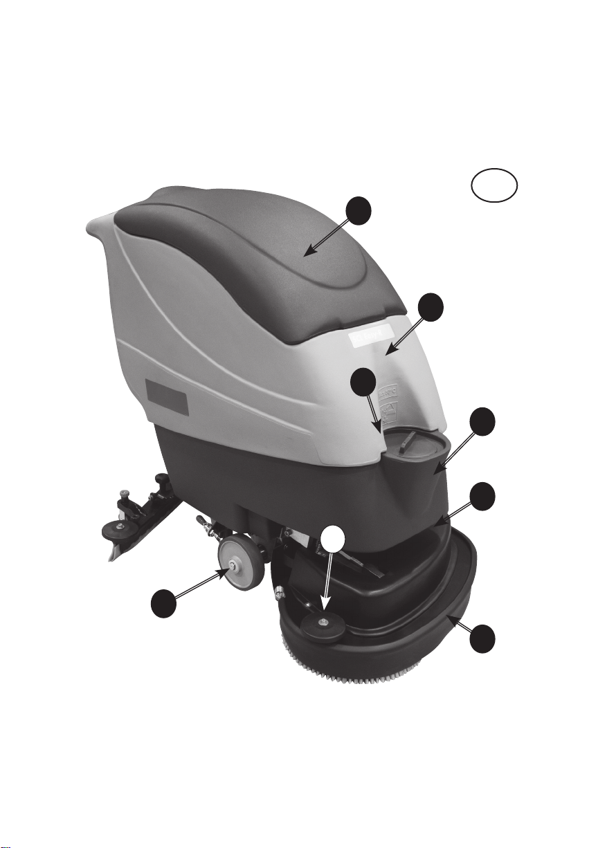
PHOTO A
1 BATTERY COMPARTMENT HOOD
2 RECOVERY WATER TANK
3 SOLUTION WATER TANK PLUG
4 SOLUTION WATER TANK
5 BRUSH MOTOR PROTECTIVE COVER
6 SPLASH GUARD
7 FRONT RIGHT BUMPER WHEEL
8 MACHINE RIGHT WHEEL
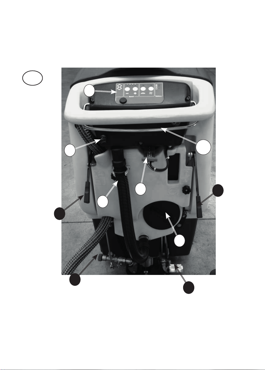
PHOTO B
1 CONTROL PANEL
2 GENERAL ON / OFF KEY SWITCH
3 SOLUTION WATER OUTLET ADJUSTING
LEVER
4 RECOVERY TANK DRAIN HOSE
5 SOLUTION WATER TANK DRAIN PLUG
6 BRUSH PLATE LIFT/LOWER PEDAL
7 RECOVERY TANK INSPECTION PLUG
8 SQUEEGEE LIFT/LOWER LEVER
9 BATTERY CHARGER CONNECTOR
10 FORWARD/REVERSE TRACTION LEVER
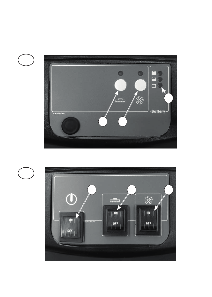
PHOTO C DC 24V MODEL WITH TRACTION
1 FORWARD/REVERSE LED INDICATORS
2 PUSH SWITCH FOR THE ADJUSTING OF
DRIVING SPEED
3 DRIVING SPEED LED INDICATORS
4 BRUSH MOTOR SWITCH
5 SUCTION MOTOR SWITCH
6 BATTERY POWER TEST
PHOTO D DC 24V MODEL WITH TRACTION
1 GENERAL ON / OFF KEY SWITCH
2 FORWARD/REVERSE TRACTION LEVER
2A FORWARD DRIVE
2B REVERSE DRIVE
3 HOUR METER
4 BRUSH MOTOR THERMAL BREAKER
5 TRACTION MOTOR THERMAL BREAKER
6 SOLUTION WATER OUTLET ADJUSTING
LEVER
7 RECOVERY TANK DRAIN HOSE
8 BATTERY CHARGER CONNECTOR
SQUEEGEE LIFT/LOWER LEVER
PHOTO E DC 24V MODEL WITHOUT TRACTION
1 BRUSH MOTOR SWITCH
2 SUCTION MOTOR SWITCH
3 BATTERY POWER TEST
PHOTO F AC 230V MODEL
1 GENERAL ON/OFF SWITCH
2 BRUSH MOTOR SWITCH
3 SUCTION MOTOR SWITCH
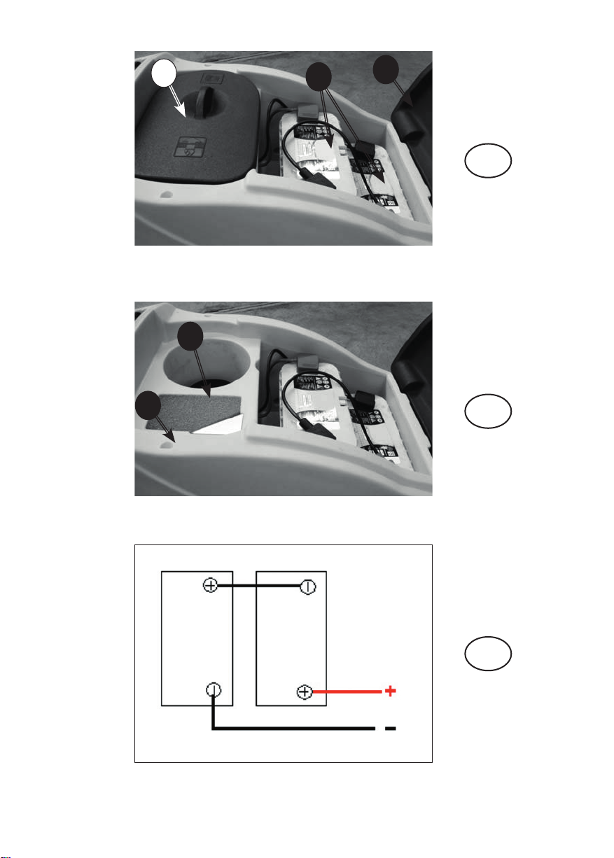
PHOTO G DC 24V MODEL
1 SUCTION COMPARTMENT HOOD
2 BATTERY COMPARTMENT WITH 12V
BATTERIES
3 BATTERY COMPARTMENT HOOD
PHOTO H DC 24V MODEL
1 SUCTION FILTER
2 VACUUM MOTOR COMPARTMENT
PHOTO I DC 24V MODEL
BATTERY CONNECTION DIAGRAM
PHOTO L
1 SUCTION HOSE CONNECTOR
2 SQUEEGEE INCLINATION ADJUSTING KNOB
3 SQUEEGEE BLADES REPLACEMENT KNOB
4 SQUEEGEE BUMPER WHEEL
5 SQUEEGEE PRESSURE ADJUSTING KNOB
6 SQUEEGEE WHEEL
7 SQUEEGEE FIXING KNOB
PHOTO M
1 SPLASH GUARD FIXING SPRING CLIP
2 SPLASH GUARD
PHOTO M
1 BRAKE LEVER
4.2.2. BATTERY
If supplied, the Pb-Acid (if not dry charged) or gel bat-
teries are ready to be installed:
Positive pole - red
Negative pole - black
4.3. ACCESSORIES
Your machine supplier can provide a complete and
updated list of all available accessories, such as
brushes, scrapers, disks, etc.
5. INSTALLATION INFORMATION
5.1. BATTERY PREPARATION
The technical features of the batteries used must
30

match those indicated in the technical features sec-
tion. Using different batteries may cause serious
damage to the machine or may require them to be
charged more frequently.
During installation or when performing any type of
battery maintenance, the operator must be equipped
with adequate safety accessories to prevent accidents.
Work far from open flames, do not short-circuit the bat-
tery poles, do not generate sparks and do not smoke.
The batteries are normally supplied full of acid solu-
tion (for the Pb-Acid type) and ready for use. In any
case, follow the steps indicated in the manual sup-
plied with the battery and carefully follow the instruc-
tions regarding safety and operating procedures.
5.2. BATTERY INSTALLATION AND
PREPARATION
These operations must be carried out by speciali-
sed personnel.
Disconnect the Anderson connector of the battery
wiring from the Anderson connector of the machine
wiring. Always hold the connectors with the hands
and never pull on the cables.
Attach the battery wiring to the battery, connec-
ting the terminals only on the poles marked with
the same symbol (red wiring “+”, black wiring “-“)!
A battery short-circuit may cause an explosion!
After checking that all the controls on the panel are in
position “0” or at rest, connect the battery connector
to the machine connector.
Close the battery compartment making sure not
to crush any wires.
5.2.1. CIRCUIT BOARD SETTINGS
CONFIGURATION
The machine is equipped to GEL battery circuit board
configured. If the operator whish to use e Pb-Acid bat-
tery, it is necessary to set the electronic circuit board
as follows:
Model “B” (DC 24V)
TO ENTER THE BATTERY THRESHOLD CONFIGURA-
TION MODE:
1) Press simultaneously the push buttons “BRUSH
MOTOR SWITCH” (Photo E - 1) and “SUCTION MOTOR
SWITCH”(Photo E - 2) within 2 seconds after switching
on the machine with the key switch (Photo D - 1). The
three LED of the battery power test (Photo E - 3) will
be ON.
2) Press “SUCTION MOTOR SWITCH” (Photo E - 2) key
within 5 seconds from the previous action; you have
now entered in the configuration mode: the green and
yellow LED of the battery power test (Photo E - 3) will
be ON.
CONFIGURATION SETTINGS ARE DISPLAYED ON
THE BRUSH LED (Photo E - 1) and on the SUCTION LED
(Photo E - 2):
Gel:
BRUSH LED (Photo E - 1) on.
SUCTION LED (Photo E - 2) off.
Pb-Acid:
BRUSH LED (Photo E - 1) off.
SUCTION LED (Photo E - 2) off.
Li-Lithium:
BRUSH LED (Photo E - 1) off.
SUCTION LED (Photo E - 2) on.
TO MODIFY CONFIGURATION SETTINGS:
Press the “BRUSH MOTOR SWITCH”(Photo E - 1)
TO SAVE THE SETTINGS AND EXIT THE MODE:
Press the“SUCTION MOTOR SWITCH”(Photo E - 2)
Once the settings have been set, we have different
battery discharge levels with differentiated interven-
tion on the machine functions as specified in the fol-
lowing table:
Battery discharge indicator and functions - Model “B”(DC 24V)
Volts
Battery Type
Battery power
test indicator
LED
Brush opera-
tion indica-
tor LED
Pb-
Acid
GEL Li Signaling Signaling Action
24,0 24,0 >25,4 Green
LED ON
LED ON All working
21,5 22,5 >23,5 Yellow
LED ON
LED ON All working
20,5 21,5 >22,6 Red LED ON LED
FLASHING
Brush motor
is not wor-
king
20,0 21,0 <22,6 Red LED
FLASHING
LED
FLASHING
Brush and
suction mo-
tors are not
working
Model “BT” (DC 24V with traction)
TO ENTER THE BATTERY THRESHOLD CONFIGURA-
TION MODE:
1) Press simultaneously the push buttons “REDUCE
SPEED” (Photo C - 2-) and“SUCTION MOTOR SWITCH”
(Photo C - 5) within 2 seconds after switching on the
machine with the key switch (Photo D - 1).The second
LED of the speed indicator (Photo C - 3B ) will be ON.
2) Press“INCREASE SPEED”(Photo C - 2+)”key within 5
31

seconds from the previous action; you have now en-
tered in the configuration mode.
THE CONFIGURATION SETTINGS ARE VISIBLE ON
THE SPEED INDICATOR LED:
1) The first two LEDs (Photo C - 3A, 3B) indicate the
type of setting of the indicator intervention threshold
an both must be ON;
2) The third and fourth LEDs (Photo C - 3C, 3D) indi-
cate the battery type: for the PB-Acid battery only the
third LED (Photo C - 3C ) should be ON, while for the
GEL battery both should be ON (Photo C - 3C, 3D)
3) To select Li batteries, press the “BRUSH ON”button
(Photo C - 4) for 2 seconds together with the “SUC-
TION ON” button (Photo C - 5) until the third LED
(Photo C - 2-C) and the fourth LED (Photo C - 3D)
switch off.
TO MODIFY CONFIGURATION SETTINGS:
1) The “INCREASE SPEED”(Photo C - 2+)”and“REDUCE
SPEED” (Photo C - 2-) keys are used to set the indica-
tor’s intervention threshold in such a way that the first
two speed indicators LEDs turn ON;
2) The “BRUSH MOTOR SWITCH” (Photo C - 4) is used
to set the PB-Acid battery type while the “SUCTION
MOTOR SWITCH” (Photo C - 5) is used to set the GEL
battery type
TO SAVE THE SETTINGS AND EXIT THE MODE:
Press the“REDUCE SPEED” (Photo C - 2-) switch and the
“SUCTION MOTOR SWITCH”(Photo C - 5) simultaneously.
Once the settings have been set, we have different
battery discharge levels with differentiated interven-
tion on the machine functions as specified in the fol-
lowing table:
Battery discharge indicator and functions - MODEL “BT”
(DC 24V with traction)
Volts
Battery Type
Battery
power test
indicator
LED
Brush
operation
indicator
LED
Pb-Acid GEL Li Signaling Signaling Action
24,0 24,0 >25,4 Green
LED ON
LED ON All working
21,5 22,5 >23,5 Yellow
LED ON
LED ON All working
20,5 21,5 >22,6 Red LED
ON
LED
FLASHING
Brush motor
is not work-
ing
Battery discharge indicator and functions - MODEL “BT”
(DC 24V with traction)
Volts
Battery Type
Battery
power test
indicator
LED
Brush
operation
indicator
LED
20,0 21,0 <22,6 Red LED
FLASHING
LED
FLASHING
Brush and
suction mo-
tors are not
working
If you do not complete the configuration procedure,
the settings remain as they were originally.
We recommend to call the assistance centre or a tech-
nician if you have problems with the settings given.
Do not open or tamper the electronic board.
5.3. BATTERY CHARGER CONFIGURATION
The machine is equipped with a battery charger con-
figurated for GEL batteries
To change the battery charger settings read the man-
ual provided by the battery charger manufacturer.
If the machine is supplied with a battery and a
charger, the setting of the machine and the charger
is carried out by the manufacturer.
In the event of changes to the equipment, i.e. the type
of battery and charger, we always recommend that
you contact your authorised service centre both for
the machine setting and the setting of the charger’s
charging curve.
As a general rule, the following criteria apply:
For Pb-acid and GEL batteries:
charging current of approx. 10-12% of the capacity in
Ah-C20
For lithium batteries:
current of approx. 40% of the capacity in Ah
Failure to comply may result in serious damage to
the battery and warranty invalidation.
5.4. MACHINE PREPARATION
Before starting to work, wear non-slip shoes, glo-
ves and any other personal protection device indica-
ted by the supplier of the detergent used or conside-
red necessary based on the operating environment.
☞Do the following before starting to work. Refer to
the relative sections for a detailed description of the-
se steps:
check the battery charge level and charge, if necessary.
Mount the brushes or scraper disks (with the abrasive
disks) that are suitable for the surface and work in-
volved.
Mount the squeegee, check that it is solidly attached
and connected to the suction hose and that the
drying blades are not too worn.
32

Make sure that the recovery tank is empty. If not,
empty it completely.
Check and completely close the detergent solution
release control.
Fill the detergent solution tank with a mix of clean water
and non-foaming detergent in an adequate concentra-
tion through the anterior hole. Leave 2 cm between the
mouth of the plug and the level of the liquid.
☞To avoid risks, become familiar with the machine
movements, carrying out test runs on a large surface
without obstacles.
To obtain the best results in terms of cleaning and
equipment service life, you should do the following
simple but important operations:
- Identify the work area, moving all possible obstacles
out of the way; if the surface is very extensive, work in
contiguous and parallel rectangular areas.
- Choose a straight work trajectory and begin wor-
king from the farthest area to avoid passing over are-
as that have already been cleaned.
6. OPERATING INFORMATION
6.1. BATTERY CHARGING
Prepare and check the battery charge according to
the instructions provided in the specific section.
Detach the battery connector from the machine po-
wer connector (the one with the gripping fins) and
connect the battery connector to the battery charger
connector.
Do not connect the battery charger to the scrub-
ber-drier’s main wiring connector.
Hold the connectors with the hands; do not pull them
using the cables.
If the machine is equipped with Pb-Acid batteries,
charge only in a well-ventilated area, lift the superior
cover and open the battery plugs.
Follow the steps indicated in the battery manufac-
turer’s operating and safety manual (see the battery
maintenance section).
If the machine is equipped with gel batteries (mainte-
nance free), follow the instructions indicated here below.
If the machine is used regularly:
Always keep the batteries connected to the battery
charger when the machine is not being used.
If the machine is not used for extended time periods:
Charge the battery during the night after the last
work period, then disconnect the battery from the
battery charger.
Charge the battery during the night before using the
machine again.
Intermediate or incomplete charging while working
should be avoided.
If the machine is equipped with Pb-Acid batteries,
use a hydrometer to check the element liquid inten-
sity on a regular basis: if one or more elements are
discharged and the others fully charged, the battery
has been damaged and should be replaced or repai-
red (refer to the battery service manual).
Close the element plugs and lower the superior cover.
Hold the connectors with the hands; don’t pull them
using the cables.
Reconnect the machine connectors.
6.2. SQUEEGEE AND SPLASH GUARD
ASSEMBLY, DISASSEMBLY AND
ADJUSTMENT
The squeegee is the main component that ensures
perfect drying.
6.2.1. SQUEEGEE ASSEMBLY
Slightly screw the two knobs ( Photo L - 7 ) into the
squeegee body and insert the squeegee into the
slots situated on the squeegee support.
Screw the two knobs ( Photo L - 7 ) in order to secure
the squeegee to the support.
Firmly insert the suction hose ( Photo L - 1 ) into the
pipe in the squeegee body.
6.2.2. SQUEEGEE DISASSEMBLY
Disconnect the suction hose from the squeegee
body.
Unscrew the two knobs ( Photo L - 7 ) that secure the
squeegee to its support and pull the squeegee to free it.
6.2.3. SQUEEGEE BLADES DISASSEMBLY /
ASSEMBLY
Disassemble the squeegee from its support (see 7.2.2)
Unscrew the knobs ( Photo L - 7 ) ( Photo L - 3 ) placed
on the squeegee body and apply some pressure on
their bolts in order to push out the plastic support of
the squeegee blades from the squeegee body.
Tear o the rubber blades from the plastic support.
Assemble the new blades on the plastic support by
the means of the plastic pins that have to be xed in
the holes placed the blades.
Push the plastic support of the squeegee blades into
the squeegee body and screw the knobs ( Photo L - 7 )
to secure it to the squeegee body.
Reassemble the squeegee to its support (see 7.2.1).
6.2.4. SQUEEGEE ADJUSTMENT
The knob screw on the squeegee support ( Photo L -
2 ) adjusts the squeegee’s inclination with respect to
the oor. The two red knobs on the sides, connected
to the rear wheels of the squeegee ( Photo L - 5 ) are
to adjust the pressure of the squeegee to the oor.
When the squeegee is perfectly adjusted, the rear
squeegee blade, sliding as it moves, bends in all
points forming an angle of 45° with the oor.
As the machine operates (advances), the knobs ( Photo
L - 2 ) ( Photo L - 5 ) can be used to adjust the inclination
and pressure of the squeegee blades on the oor.
Squeegee drying must be uniform along the entire
drying line: damp patches mean that drying is insu-
33

cient; turn the adjustment knobs to optimize drying.
6.2.5. SPLASH GUARD ASSEMBLY/ DISASSEMBLY
The splash guard is assembled to the brush plate with
a spring holder linked to the brush plate itself ( Photo
M - 1 ).
To disassemble the splash guard simply detach the
spring holder and pull the splash guard.
To reassemble, x the splash guard in the brush plate,
and then hook the steel cable to one side of the plate
and the spring holder to the other side of the brush
plate.
6.3. BRUSH ASSEMBLY / DISASSEMBLY
Never use the machine if brushes or scrapers and
abrasive disks are not perfectly installed.
Assembly:
Make sure that the brush plate is raised; otherwise lift
it by following the instructions provided in the spe-
cific section.
Make sure that the ignition key on the control panel
is in position “0”.
Bring the brushes (or the guide disks equipped with
abrasive disks) near the connections, under the brush
plate; lower the washing plate and start the brushes
turning: the brushes/discs couple automatically;
Do not allow the length of the rows of brushes to
become lower than 1 cm.
Do not allow the thickness of the abrasive disks to
become less than 1 cm.
Working with excessively worn brushes or excessi-
vely thin abrasive disks may damage the machine
and the floor.
Regularly check the wear on these parts before star-
ting to work.
Disassembly or replacement:
Make sure that the brush plate is raised; otherwise lift
it by following the instructions provided in the spe-
cific section.
Make sure that the ignition key on the control panel
is in position “0”.
While holding the brushes (or the guide disks) with
the hands under the plate, turn them in the rotation
direction while lowering to release them from the
guide plate.
6.4. FILLING AND DRAINING THE DETERGENT
SOLUTION TANK
☞The temperature of the water or the detergent
should never exceed 50°C.
• Always empty the detergent solution tank before
filling it up.
To fill:
• Remove the plug in the front of the machine .
• Leave 2 cm between the mouth of the plug and the
liquid level. Do not fill beyond this point!
• Add the required quantity of the chemical product,
considering the percentage indicated by the sup-
plier, with reference to the full tank capacity listed on
the product sheet.
• Use only those products suitable for the floor and
the dirt to be removed.
The machine was designed to be used with non-
foaming and biodegradable detergents made speci-
fically for scrubber-driers. The use of other chemical
products (such as sodium hypochlorite, oxidisers,
solvents or hydrocarbons) may damage or destroy
the machine.
• Follow the safety regulations specified in the relati-
ve section and indicated on the detergent container.
• Contact the machine manufacturer to obtain a com-
plete list of available and suitable detergents.
☞Always add the detergent after filling the tank with
water to prevent foam from being created inside.
• Do not leave the water hose unattended and insert
it completely into the tank: the hose might move and
get sensitive parts of the machine wet.
Close the tank with its plug…
To drain:
• Unscrew the cock.
• Close the drainage plug firmly.
6.5. DRAINING THE RECOVERY TANK
The dirty water must be drained in accordance with
national regulations.
The user is completely responsible for ensuring com-
pliance with such rules.
After the detergent solution is finished, always empty
the recovery tank before filling it again.
In general, the recovery tank can be emptied whene-
ver required, and even during intermediate phases of
the work cycle.
The recovery tank volume is higher than the deter-
gent solution volume, therefore a potentially dan-
gerous situation for the suction motor should never
occur. In any case, a safety float turns off the suction
motor if the dirty liquid level is too high.
If water or foam starts leaking from under the
tanks for any reason, immediately turn off the suction
motor and empty the recovery tank.
To drain the tank:
Drive the machine to a suitable location to drain the
dirty water and preferably near a toilet or a sewer
drain (comply with the national regulations for waste
water disposal).
Turn off the machine and remove the key from the
panel.
Detach the drain hose from the hook and, keeping it
high, unscrew the plug.
Lower the drain hose toward the selected drainage
point.
The emptying operation can be interrupted quickly
and whenever required just by raising the drain hose.
Check how much dirt is still in the tank and, if neces-
34

sary, wash it inside through the inspection hole by
unscrewing the rear window .
Fully tighten the drain hose with the screw plug and
hang it on the support behind the machine. The drain
hose plug must be airtight, otherwise the subsequent
pressure loss will reduce drying efficiency.
6.6. DRIVING THE MACHINE
Check connection between the power and battery
connectors, located under the control panel.
Put the ignition key in and turn it.
Check battery charge status via the control unit and,
if sufficient, select the running speed wanted, operate
the brush control key and the suction control key. Now
open the solution cock by lowering the detergent do-
sage lever which is at the back of the machine, lower
the suction unit by lowering the squeegee control le-
vel, lower the washing unit, levering with your foot on
the brush plate control lever.
Move forwards, pulling the forward lever up . Re-
member to lift the floor cleaner before reversing to
avoid damaging it.
6.7. WORK METHOD
6.7.1. PREPARATION AND WARNINGS
Remove any loose solid residue from the surface
to be treated (using suitable tools, such as vacuum
cleaners, sweepers, etc.). It this is not done, the solid
dirt might prevent the squeegee from operating cor-
rectly, reducing drying efficiency.
This machine can driven only by trained personnel.
6.7.2. OPERATING CONTROLS
• Battery charge control: the sequence of lights pro-
gressively turns off until the battery is discharged .
When the red light turns on, turn off the brush motor,
close the solution supply, finish drying the small resi-
dual moisture and go to the battery charging area to
charge the battery.
The batteries may be irreparably damaged if the
residual charge level drops too low (see the battery
operating manual). Do not force the battery dischar-
ge beyond the safety limits, turning the key off and
on or in any other manner.
When an abnormal situation occurs, such as when
the machine doesn’t have enough power and the
safety devices don’t trip, stop immediately: follow
the instructions in the troubleshooting section and
contact a specialised worker to check the discharge
control devices.
6.7.3. DIRECT SCRUBBING OR FOR SLIGHTLY
DIRTY SURFACES
Scrubbing and drying in a single pass.
Prepare the machine as previously described.
Check connection between the power and battery
connectors, located under the control panel.
Put the ignition key in and turn it.
Check battery charge status via the control unit and,
if sufficient, select the running speed wanted, opera-
te the brush control key and the suction control key.
Now open the solution cock by lowering the deter-
gent dosage lever which is at the back of the machi-
ne, lower the suction unit by lowering the squeegee
control level, lower the washing unit, levering with
your foot on the brush plate control lever .
Move forwards, pulling the forward lever up or push
it down to reverse . Remember to lift the floor cleaner
before reversing to avoid damaging it.
Never use the machine without the detergent solu-
tion: the floor might be damaged.
6.7.4. INDIRECT SCRUBBING OR FOR VERY
DIRTY SURFACES
Scrubbing and drying in various passes.
Prepare the machine as previously described.
First set of operations:
Check the connection between the power and batte-
ry connector, located under the control panel.
Put the ignition key in and turn it.
Check battery charge status via the control unit and,
if sufficient, operate the brush control key. Now open
the solution cock by lowering the detergent dosa-
ge lever which is at the back of the machine, lower
the brushing unit by levering with your foot on the
brush plate control lever. Move forwards, pulling the
forward lever up .
Allow the detergent solution to work on the dirt
according to what is indicated in the information
relative to the detergent used.
Second set of operations:
Proceed as explained in the previous “Direct Wa-
shing” paragraph (7.7.3) to also proceed with drying
the floor.
Never use the machine without the detergent solu-
tion: the floor might be damaged.
6.7.5. POST-SCRUBBING OPERATIONS
Cut off the supply of detergent.
Lift the brush unit and turn off the brush motor.
After having completely dried any traces of water
on the surface, wait a few seconds and then lift the
squeegee and turn off the suction motor.
Move to a suitable location to drain the tanks (as de-
scribed in 7.4 and 7.5).
Empty and clean the tanks (see sections 7.4 and 7.5).
Turn off the machine using the key and remove it
from the control panel.
If necessary, charge the battery (see the relative section).
6.8. SPECIFIC INSTRUCTIONS FOR THE USE OF
POWER MAINS AC 230V MODEL
The power mains AC 230V machine may be turned on
only if the voltage indicated on the tag corresponds
35

with the available voltage and that the electrical out-
let is grounded (earthed).
Do not damage the feed cable; do not crush or pull on it.
ATTENTION Make sure that the power cable does
not come into contact with the rotary brushes.
ATTENTION !!! - The power mains AC 230V ma-
chine has parts, which are connected to the cur-
rent; contact with these could cause grave injuries
or even death.
- Before executing any type of operation on the ma-
chine always disconnect it from the electrical source.
- Never touch electric cables that are defective or worn.
- Before gaining access to the electrical system it is
always necessary to disconnect the machine from
the electrical source by removing the plug from the
socket-outlet.
- In the case of defective, damaged, or cracked electric
cables, replace immediately with authentic replace-
ment parts.
- The network of connections must be protected from
water spray.
-The patch cord for the connection of the machine
to the mains power must conforms to current
safety rules.
- The electrical system to which the machine is con-
nected must be equipped with a cutout box.
- It is absolutely forbidden to use the machine in
proximity to swimming pools or stretches of water.
EMERGENCY SITUATIONS
In case of emergency:
- Immediately disconnect the machine from the
power mains.
- Immediately apply proper rst-aid.
If an accident should occur the machine must not be
put into operation until a technician authorized by
the manufacturer has examined it.
7. MAINTENANCE INFORMATIONS
36
When needed After every use Weekly Monthly
Remove and wash the squeegee X
Drain the recovery tank X
Drain, rinse with clean water or sanificate the recovery tank X
Charge the batteries X X
Check the acid level in the battery cells (if batteries are not mainte-
nance-free) X
Check the wear of the squeegee rubber blades X
Open and clean the suction filter X
Removebrushesandcheck for brush wear, foreign bodies and wrapped
belts X
Verify the machine general conditions. X
Open and clean the solution water filter X
Verify that suction hose and conduct are free from obstructions X
Check and clean the pivoting wheels X
Check wear and function of traction drive belt or chain; if necessary,
adjust belt or chain tension X
Clean the brush plate, squeegee support and squeegee X
Check the lifting/lowering of the brush plate. X
Check the lifting/lowering of the squeegee. X
Grease the moving parts. X
Check the control cable for the opening of the solution water tap. X
Descale water hoses. X

37
Turn the key, remove it from the control panel and
disconnect the battery from the machine wiring.
☞All work on the electrical system as well as all main-
tenance and repair operations (especially those not
explicitly described in this manual) should be carried
out only by authorised service centres or by speciali-
sed technical personnel who are experts in the sector
and in the pertinent safety regulations.
Performing regular maintenance on the machine,
and carefully following the manufacturer’s instruc-
tions, is the best guarantee for obtaining the best
performances and extended machine service life.
7.1. TANKS
Drain the two tanks as described in the relative sec-
tions.
Remove any solid dirt by filling and draining the
tanks until all dirt has been eliminated: use a washing
hose or similar tool to do this.
Water hotter than 50°, a high-pressure cleaner
or excessively powerful sprays may damage the
tanks and the machine.
Leave the plugs of the tanks open (only while the ma-
chine is not being used) so that they can dry and thus
prevent the formation of foul odours.
7.2. SUCTION HOSE
Detach the suction hose from the squeegee.
Now you can wash the hose and remove any obstruc-
tions.
Firmly insert the hose on the squeegee body.
7.3. SQUEEGEE
Do not handle the squeegee with bare hands:
wear gloves and any safety clothing needed to carry
out the operation.
Detach the squeegee from the machine and clean it
under running water using a sponge or a brush.
Check the efficiency and the wear on the strips in
contact with the floor. They are designed to scrape
the film of detergent and water on the floor and to
isolate that portion of the surface to enhance the
vacuum of the suction motor: this ensures that the
machine will dry very efficiently. Working constantly
in this manner tends to round or to deteriorate the
sharp edge of the strip, thus reducing drying efficien-
tly. This is why the squeegee strips must be replaced.
To replace the worn blades, follow the instructions in
the relative section. Turn the blades around to wear
down the other sharp corners or to install new ones.
7.4. ACCESSORIES
Remove and clean the brushes or the scraper disks.
To avoid damaging the floor and the machine, careful-
ly check if foreign matter, such as metallic parts, screws,
chips, cords or similar items, has become jammed.
Check that the brushes are flat as they work on the
surface (check for any irregular wear on the brushes
or on the abrasive disks). If necessary, adjust the slant
of the action on the floor.
Use only the accessories recommended by the manu-
facturer: other products may reduce operating safety.
7.5. MACHINE BODY
Use a sponge or a soft cloth to clean the exterior of
the machine and, if necessary, a soft brush to elimi-
nate tough dirt. The machine’s shockproof surface
is rough to make it harder to see scratches caused
during use. However, this does not make it easier to
remove tough stains on the surface. Steam machines
can be used but it’s prohibited to use hoses with run-
ning water or a high-pressure cleaner.
7.6. BATTERIES
PB-ACID
Carry out maintenance operations in accordance with
the manufacturer’s instructions and with all the other
instructions provided in this manual.
Exposing the element plates (not completely immersed
in the acid solution) will lead to rapid oxidation and irre-
parably reduce the element’s operating capacities.
An overflowing acid solution may corrode the machine.
Use battery chargers recommended by the manufac-
turer and, in any case, those that are suitable for the
type of battery to be charged.
Always charge batteries in well-ventilated rooms:
there is an explosion risk!
The use of gel or maintenance-free batteries is highly
recommended.
GEL
Carry out maintenance operations in accordance
with the manufacturer’s instructions and with all the
other instructions provided in this manual.
Use only those battery chargers recommended by
the manufacturer.
☞If the batteries are not used, in either case, for an
extended period of time, disconnect them and re-
store the charge within the time limits specified for
the type of battery used (generally and as a precau-
tion, no more than 3 months for Pb-acid/GEL/AGM
batteries, 6 months for Li-ion batteries).
The manufacturer accepts no liability for damage to
batteries caused by failure to follow this procedure.
7.7. FUSES AND THERMAL BREAKERS
The machine is equipped with electric protection
devices on the main operating components to avoid
costly malfunctions.
Thermal cutouts are installed to protect the drive mo-
tor wherever foreseen and the brush motor.
When one of these breakers trips automatically, the
disabled function can be reactivated by fully depres-
This manual suits for next models
2
Table of contents


