EXE XDDL Series User manual

Rev. 03 del 17/09/2018 Pag. 1 / 40
USE AND MAINTENANCE MANUAL
Motor Controller XDDLxx LVC
Model: XDDL4 XDDL8 XDDL16 XDDL24
Serial Number: _ _ _ _ _ _ Years of Construction : 20 _ _
Official Language: ITALIAN Manual Language: ENGLISH
[ TRANSLATION OF THE ORIGINAL INSTRUCTIONS ]

Rev. 03 del 17/09/2018 Pag. 2 / 40
,
Keep this manual for future consultation.
Provide this manual to all Motor Controller operators and maintenance technicians.
For further information and clarifications or if there are any problems with this product, contact SRS or LITEC
ITALIA.
Before using the Motor Controller, fill out the following information. This information must be provided
whenever contacting technical support.
Company name and
address (1)
Date of purchase
Company name and
address (2)
Date of purchase
Company name and
address (3)
Date of purchase
Reproduction, transmission or computerized archiving as wells as translation into another language, in any
form, in whole or in part, are absolutely forbidden without prior written authorization from SRS.
Revision
Changes
Description
DATE
01
Entire Manual
First issue
2014
02
Entire Manual
Changes according to standards and decrees
05/10/2017
03
Entire Manual
Technical data and drawings updates
17/09/2018
MANUFACTURER
SRS LIGHT DESIGN s.r.o.
Rybnicna 36/D, SK-
83106 Bratislava, Slovak Republic
Tel: +421244681417
www.srslight.com
DISTRIBUTOR
LITEC ITALIA S.R.L.
Via Martin Luther King 70,
I-31032 Casale sul Sile (TV), Italy
Tel: +390422997300
www.exetechnology.com
www.litectruss.com

Rev. 03 del 17/09/2018 Pag. 3 / 40
TABLE OF CONTENTS
1. GENERAL INFORMATION................................................................................................................................5
1.1. SCOPE OF THE MANUAL..............................................................................................................................5
1.2. SAFETY SIGNS...............................................................................................................................................6
1.3. REPAIR - REPLACEMENT - WARRANTY POLICY.......................................................................................6
2. MACHINE PRESENTATION..............................................................................................................................8
2.1. INTENDED USE..............................................................................................................................................8
2.2. IDENTIFICATION OF EXE-DRIVE MOTOR CONTROLLER .........................................................................9
2.3. GENERAL DESCRIPTION..............................................................................................................................9
2.4. PRINCIPLE OF OPERATION .......................................................................................................................12
2.5. TECHNICAL DATA........................................................................................................................................14
2.5.1 EXE-Rise chain hoist link............................................................................................................15
2.6. AIRBORNE NOISE EMISSION.....................................................................................................................15
3. SAFETY WARNINGS.......................................................................................................................................16
3.1. GENERAL SAFETY WARNINGS..................................................................................................................16
3.2. SPECIAL SAFETY WARNINGS....................................................................................................................17
4. MOVEMENT AND INSTALLATION.................................................................................................................18
4.1. MOVEMENT & TRANSPORT .......................................................................................................................18
4.2. TRANSPORT AND STORAGE .....................................................................................................................18
5. USE...................................................................................................................................................................19
5.1. ELECTRIC WIRING.......................................................................................................................................19
5.2. CONNECTING THE XRH-C PUSHBUTTON PANEL...................................................................................19
5.3. CONTROL UNIT STARTUP..........................................................................................................................21
5.3.1. Using the equipment in individual mode.....................................................................................21
5.3.2. Using the equipment in individual mode with the XDRH pushbutton panel ...............................22
5.3.3. Use in “LINK” BETWEEN CONTROLLER mode........................................................................24
5.3.4. Use in “LINK” BETWEEN CONTROLLER mode with XDRH pushbutton panel ........................26
5.3.5. Use in PICKLE mode with the XCLH1 pushbutton panel...........................................................28
5.4. ERRORS .......................................................................................................................................................28
5.5. EMERGENCY INTERVENTIONS.................................................................................................................31
6. INSPECTIONS..................................................................................................................................................33
6.1 INITIAL INSPECTION AND AT EVERY USE ...............................................................................................33
6.2 PERIODIC INSPECTION ..............................................................................................................................33
6.3 EXTRAORDINARY INSPECTION.................................................................................................................34
7. DEMOLITION AND DISPOSAL.......................................................................................................................34
8. DECLARATION OF CONFORMITY ................................................................................................................35
9. MAINTENANCE AND REPAIRS REGISTRY..................................................................................................36
INDEX OF FIGURES

Rev. 03 del 17/09/2018 Pag. 4 / 40
Figure 1
EXE-Drive XDDL4 Low Voltage Control
8
Figure 2
EXE-Drive XDDL8 Low Voltage Control
8
Figure 3
EXE-Drive XDDL16 Low Voltage Control
8
Figure 4
EXE-Drive XDDL24 Low Voltage Control
8
Figure 5
EXE-Drive Motor Controller Plate
9
Figure 6
DL8-LVC Frontal and Rear View
9
Figure 7
DL8-LVC Frontal and Rear View
10
Figure 8
DL8-LVC Frontal and Rear View
10
Figure 9
DL8-LVC Frontal and Rear View
11
Figure 10
DDL4-LVC Front View Description
12
Figure 11
Pickle and Group Stop Function
13
Figure 12
DDL4-LVC Rear View Description
13
Figure 13
Spider
19
Figure 14
XRH-C Pushbutton panel
20
Figure 15
DL8 and RH8C
21
Figure 16
Declaratio of Conformity example
35
INDEX OF TABLES
Table 1
Connector
14
Table 2
Technical Data
15
Table 3
EXE-Rise chain hoist link
15
ATTACHED DOCUMENTATION
This manual is an integral part of the EXE-Drive Motor Controller and contains the EXE-Drive Motor Controller
Declaration of Conformity.
The Declaration of Conformity is an integral part of the manual, therefore it is also an integral
part of the EXE-Drive Motor Controller.
The Declaration of Conformity contains a list of directives and standards.

Rev. 03 del 17/09/2018 Pag. 5 / 40
1. GENERAL INFORMATION
Thank you for choosing a XDDL Motor Controller from the EXE-Drive line produced by SRS and distributed by
LITEC ITALIA.
Do not use the Motor Controller EXE-Drive until all operators have read this manual
thoroughly. Failure to follow these instructions could endanger the safety of individuals
and/or lead to injuries or even death.
The manual must be followed to insure safe, reliable, and proper operation of the Motor
Controller EXE-Drive in order to eliminate the possibility of injuries and/or damage to the
equipment.
This manual, along with the other documents included in the package, are an integral part of the equipment
and must accompany the product throughout its life cycle, even if it is transferred to another owner. The
manual must be kept clean and protected from rain, humidity and any other agent that could cause it to
deteriorate. It must be complete and intact in order to be legible for future consultation.
The information contained in this manual is correct as of the time it was printed but may be
subject to changes without notice or notification (the revision of the document shown in the
heading is essential for identifying the version you possess), when necessary, according to the
SRS continuous improvement policy.
Make sure this manual is always available to all operators and maintenance technicians.
The customer is responsible for supervising all staff involved and for making sure they are aware of the risks
and safety implications related to the use of the EXE-Drive Motor Controller.
1.1. SCOPE OF THE MANUAL
The purpose of this manual is to inform operators of proper installation and use of the EXE-Drive Motor
Controller to prevent and minimize risks during man-machine interaction. The manual also contains
information regarding maintenance operations that is intended solely for maintenance technicians.
The information provided in this manual includes important instructions on the safety of the machinery and all
individuals involved. Carefully follow all instructions before performing any installation and maintenance
operations and before using the Motor Controller.
Failure to follow these instructions could endanger the safety of individuals and/or cause material or other
damages.
Before using the EXE-Drive Motor Controller, each operator must become familiar with the warnings,
instructions, and recommendations contained in this manual. Implementation of all safety precautions
specified in this manual is required before performing these operations. If any steps are not clear, please
contact SRS or its distributor.
It is the sole responsibility of the customer (employer) to check with the local authorities to
determine whether the EXE-Drive Motor Controller is compliant with local legislation.
Lifting operations permitted by the manufacturer are for set up purposes without people
under or in proximity of moving loads.

Rev. 03 del 17/09/2018 Pag. 6 / 40
1.2. SAFETY SIGNS
This manual contains various safety signs in order to identify and indicate particular situations. The safety
signs are phrases that provide information on the potential risks and proper procedures, as reported below:
WARNING: indicates a very hazardous situation that, if not prevented, could lead to serious
injury or death.
CAUTION: indicates a hazardous situation that, if not prevented, could lead to slight or moderate
injury.
NOTE WELL: indicates the procedures not related to injury.
OPERATOR/S: Personnel in charge to the various activities related to the entire life cycle of the
machine, handling, to the installation and use.
MAINTENANCE TECHNICIANS: Personnel responsible for maintaining the machine and its safe
and satisfactory operation. It is required to carry out all necessary maintenance. He must be fully
acquainted with the equipment and the risks it presents and with the intervention procedures
envisaged.
EXPERTS TECHNICIAN: a person who, for his training and experience, possesses skills and
knowledge in the field of control systems and lifting equipment and sufficient familiarity with the
main regulations to determine any deviations from the conditions envisaged.
1.3. REPAIR - REPLACEMENT - WARRANTY POLICY
Before shipping, the performance of the EXE-Drive Motor Controller is checked by SRS or by authorized
service centres. The manufacturer guarantees that upon delivery to the customer, the goods is free of
manufacturing and material defects.
Upon receipt of the merchandise, quantitative and qualitative controls must be performed. If there is a
nonconformity, the merchandise must be immediately returned to the carrier.
The warranty is only valid for new equipment.
The purchaser must not remove or allow anyone to remove the tags and instructions from the product.
If a warranty claim must be made, or if there is a malfunction or parts are needed, contact SRS or its
distributor. This warranty may be replaced by all other express or implied warranties at the complete
responsibility of the purchaser.

Rev. 03 del 17/09/2018 Pag. 7 / 40
WARRANTY PERIOD
The EXE-Drive Motor Controller is provided with a limited warranty of one year from the date of purchase. The
warranty covers the mechanical parts, excluding the electrical and others parts subject to wear. The warranty
period starts on the day of delivery, substantiated by a purchase receipt such as an invoice or delivery note, or
copies of them.
In the event of injury or property damage due to use of the product, the purchaser must provide written
notification of the injury or damage to the manufacturer or one of its distributor within 48 hours.
Repairs under warranty do not renew or extend the warranty period.
REPAIR AND REPLACEMENT POLICY
If the properly maintained EXE-Drive Motor Controller has a performance problem due to material or
manufacturing defects, after inspection by SRS or an authorized operator, repair or replacement of the unit will
be without charge for the original purchaser.
The repair/replacement policy applies only to EXE-Drive Motor Controllers that have been properly used and
inspected/stored as shown in this manual. This policy does not apply to parts subject to normal wear, to
abuse, to insufficient and improper maintenance, to inadequate and improper use, and in the presence of
hostile environments.
WARRANTY LIMITATIONS
The warranty does not cover abuse and negligence. SRS shall not be liable for any damage
resulting from failure to follow the instructions in this manual.
The use of replacement parts not supplied by SRS or its distributor and changes made to SRS project by third
parties also make the warranty void. The warranty does not cover:
- damage due to transport;
- improper or inadequate use;
- negligent handling;
- chemical or abrasive actions;
- connection to voltages that differ from the
recommended ones;
- improper or inadequate maintenance;
- excessive heat;
- parts subject to normal wear and tear;
- use outdoors without appropriate measures;
- malfunction or defect due to the use of products
not supplied by SRS;
- abuse or damage resulting from an accident;
- failure to follow the instructions in this manual;
- not used, inspected, or maintained in compliance
with current laws and the instructions written by the
manufacturer;
- installed, repaired, tampered with, or changed
without following laws and instructions.
The limited warranty excludes electrical parts and consumables.
The manufacturer is in no way responsible for accidental or consequential damages as these terms are
defined in section 2-715 of the Uniform Commercial Code UCC. The purchaser must collaborate with SRS or
one of its distributors in investigating the injury or damage and in defence of any requests for compensation. If
the Purchaser does not comply with this section or if the injuries/damages are caused, in whole or in part, by
the Purchaser’s failure to comply with federal or state laws regarding safety, the Purchaser must indemnify
and hold the manufacturer harmless from any claim, loss, or expense for injuries or damages related to use of
the product.

Rev. 03 del 17/09/2018 Pag. 8 / 40
2. MACHINE PRESENTATION
The EXE-Drive Motor Controller is the result of years of experience in the structure moving sector for the
entertainment and events industry. The high level of technology applied has led to the creation of a product
that enhances the primary features of a Motor Controller combined with ease of use.
Like all products in the EXE-Technology brand, the Motor Controller is made according to the highest quality
standards, using high precision electronic and electromechanical components, which ensure long-term use of
the product without problems.
2.1. INTENDED USE
The EXE-Drive Motor Controller is only intended for the use for which it was expressly designed, namely to
control and move EXE-Rise electric chain hoists for the entertainment and events industry. To check the
compatibility between the EXE-Drive Motor Controller and EXE-Rise electric chain hoists, consult section 3.5
in this manual.
Any other use should be considered improper and therefore dangerous.
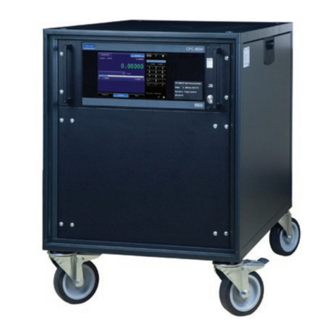
Figure 1: “EXE-Drive XDDL4 Low Voltage Control” Figure 2: “EXE-Drive XDDL8 Low Voltage Control”
Figure 3: “EXE-Drive XDDL16 Low Voltage Control” Figure 4: “EXE-Drive XDDL24 Low Voltage Control”

Rev. 03 del 17/09/2018 Pag. 9 / 40
2.2. IDENTIFICATION OF EXE-DRIVE MOTOR CONTROLLER
The information plate is in English. The translation of the content in other languages is provided in
this manual.
Figure 5: “EXE-Drive Motor Controller Plate”
EXE-Drive Motor Controllers have a visible, legible, and indelible plate that contains the following indications
(please see Figure 5 as example):
1. 965056: example of manufacturer product code;
2. Type: LT XDDL8-LV: commercial name;
3. Power: AC3-230V/400V / 50Hz, 3x32A max: power supply;
4. S/N: 170556: Serial Number;
5. MFC: 2017: Years of construction;
6. EXE-Technology Logo;
7. CE marked;
8. Waste Disposal Symbol;
9. Made by: Company name and address of the manufacturer.
2.3. GENERAL DESCRIPTION
The EXE-Drive Motor Controller was designed to meet safety standards. In fact, the device is equipped with:
- A general differential magnetothermic switch for protecting the entire machine.
- Adjustable magnetothermic protection for each motor output.
- Protection on the control circuit through fuses located inside the device.
- Release system coupled to the general differential magnetothermic switch.
DL4-LVC
Figure 6: “DL4-LVC Front and Rear View”
FRONT VIEW
REAR VIEW

Rev. 03 del 17/09/2018 Pag. 10 / 40
DL8-LVC
Figure 7: “DL8-LVC Front and Rear View”
DL16-LVC
Figure 8: “DL16-LVC Front and Rear View”
REAR VIEW
FRONT VIEW
FRONT VIEW
REAR VIEW

Rev. 03 del 17/09/2018 Pag. 11 / 40
DL24-LVC
Figure 9: “DL24-LVC Front and Rear View”
The EXE-Drive Motor Controller was designed to manage up to 4/8/16/24 chain hoists that are electrically
compatible, either separately or simultaneously, which are controlled through switches located on the front
panel or using a wireless pushbutton panel. The GO/STOP buttons can be connected with a link connector.
The unit is equipped with automatic cyclic sequence control of the input supply phases. This module controls
the main voltage of 400V ±10% AC and the star configuration. If there is a problem with the voltage, the user
will be warned and the unit will not move with any hoist. Plus, if a cable is disconnected, the Motor Controller
will stop to insure maximum safety.
The Motor Controller does not work in the following situations:
A phase is missing
There is an under-voltage situation on the power lines
There is an over-voltage situation on the power lines
All electrical components have UL/CSA and CE certification and are compliant with European Directives. The
components are housed in a 19 inch Rack powder coated robust steel case. The complete unit has CE
marking and is compliant with the standards/directives shown in the Declaration of Conformity attached to this
manual.
FRONT VIEW
REAR VIEW

Rev. 03 del 17/09/2018 Pag. 12 / 40
2.4. PRINCIPLE OF OPERATION
The Motor Controller was designed and built to simultaneously or individually manage from 1 to a maximum of
4/8/16/24 electric chain hoists that are electrically compatible. It can be operated in two modes:
DIRECT: the Motor Controller will only operate with the commands located on the front of it.
REMOTE: the Motor Controller will only operate with the commands located on the pushbutton panel.
On the Motor Controller, only the emergency STOP button is enabled in both modes. In the event of a
failure or emergency, this button allows you to shut off the voltage to the Motor Controller command
circuit and, at the same time thanks to a release coil coupled to the main switch, to move the switch to the
OFF position and completely shut off the system, putting it in safe mode.
PICKLE: the Motor Controller supplies power but does not operate the electric chain hoists. In PICKLE
mode, operation occurs locally and only on a single hoist using a PICKLE XCLH1 pushbutton panel.
Never use the up-down selectors to invert the direction of the motors while pressing the GO button. This could
be very dangerous to yourself and others.
An example of the front panel of the Motor Controller XDDL4-LVC is shown below. The model XDDL8-LVC
differs only in the number of chain hoists that can be connected to them.
Figure 10: “XDDL4-LVC Front View Description”
POWER (ELECTRIC SUPPLY): indicates the status of the power supply.
- RED: phase misalignment, missing phase, undervoltage or over voltage - check the network.
- GREEN: there are no power supply problems, the Motor Controller is functioning.
STATUS: indicates the status of the LEDs on the Motor Controller and remote unit.
ORANGE: indicates that the Direction switches are active on the remote unit.
RED: the GO button is pressed on the front panel or on the RC-x remote digital unit.
GREEN: the unit is functioning normally / E-stop and RESET are not necessary.
E-STOP: indicates the state of the LEDs for the E-stop functions:
- ORANGE: state after the E-stop of the loading cell - press/release the E-STOP to reset the state
- RED: E-STOP condition received from the line

Rev. 03 del 17/09/2018 Pag. 13 / 40
- RED FLASHING: The emergency STOP button is active on the base unit
- GREEN: The unit is functioning normally / E-stop and RESET are not necessary.
EMERGENCY STOP: is a red button. After the STOP button has been pressed, the system is locked in an
inactive position and to restart it, the button must be turned clockwise. The system must also be RESET.
GO: is a white button. When it is pressed, it runs all of the selected channels and the related electric chain
hoists move. When the GO button is pressed again, power to the motors is cut off.
DIRECTION SWITCHES: allow you to change the direction of each electric chain hoist individually or in a
group. The movement direction is signalled by a LED located near the switch.
PICKLE POWER: lets you power and not run the electric chain hoists. With the switch set to ON, operation
occurs locally and only on a single hoist using a PICKLE XCLH1 pushbutton panel. Local operation is useful
for taking up the slack on the chains of the individual hoists before running them simultaneously.
The XDDL16 / 24-LVC models differ from the XDDL4 / 8-LVC for the following functions:
PICKLE: This function is activated via a key selector as shown in Figure 10-b. The selector must be placed in
the Pickle position.
GROUP STOP: This function is activated / deactivated with the GROUP STOP DISABLE button (Figure 10-b).
The color is orange when the function is off.
Figure 11: “Pickle e Group Stop function”
An example of the rear panel of the XDDL4-LVC is shown below. The other models differ only in the number
of electric chain hoists that can be connected to them.
Figure 12 “XDDL4-LVC Rear View Description”

Rev. 03 del 17/09/2018 Pag. 14 / 40
REMOTE/LINK CONNECTOR - Neutrik NC5-MAH/FAH: These are for connecting the electric chain hoists or
an RCx remote digital connection. They can be controlled using a GO and STOP emergency button with an
RH remote digital unit.
Poles
Function
NOTE
1
CMN data
Common data
2
Data-
Less Data
3
Data+
More Data
4
DC1
Power supply for RC-X
DC12-36V
5
DC2
Power supply for RC-X
DC12-36V
Table 1: “Connector”
POWER SUPPLY CABLE: For the main input, a 5G6mm2 cable is used with a CEE 32/5p connector. The
cable has an MPA end to easily change the phase alignment. The fuse for the electronic transformer is type
T2.5A.
2.5. TECHNICAL DATA
GENERAL INFORMATION
Model and Type
XDDL4/8/16/24 Low Voltage Controller
Case
Steel with grey powder coating.
MAIN CHARACTERISTICS
RCD Protection for input power supply
MCB protection for channel
4/8/16/24 x Inverter Contactor for direct control
4/8/16/24 x 3 - Channel position switches (UP-OFF-DOWN)
4/8/16/24 x green LEDS that indicate the channel UP selection
4/8/16/24 x white LEDS that indicate the channel DOWN selection
3 x Red Neon Voltage presence indicators (L1-L2-L3)
XLR 5-pin male/female OUT Link panel connector
XLR 5-pin IN Link + REMOTE panel connector
2x XLR 4-pin for E-stop link function.
1 metre of XLR 5-pin link cable is supplied
Emergency Button
White GO button (which requires the presence of an operator) with flashing light indication
Phase recognition safety function - The unit will not function if the three-phase sequence
supply is not direct.
2 Pickle function switches (ON-OFF)
TECHNICAL DATA
Input - Y power supply connector - Δ 230
VAC: Only upon request, please contact
us for more information.
Pin with CEE 400VAC ± 10% –32A (XDDL4/8)/ 63A (XDDL16/24) –3 P+N+E 6h - @ 50-
60Hz mechanical phase inverter
Output
2 x female connectors from the Socapex 19-pin panel - crimped connector.
1-2 power supply channels 3-5-400VAC+PE Channel control (UP-DOWN-COMMON)
Linked systems
Up to 9 XDDL units of any type or 8 XDDL units of any type plus a remote control
pushbutton panel
Miniature Circuit Breaker (MCB)
4 x 10A
Residual Current Device (RCD)
30mA
Cable length
1.5m
Operating temperature
-20°C +40°C
Protection Class Ip
P20

Rev. 03 del 17/09/2018 Pag. 15 / 40
Compatible with EXE-Rise electric chain
hoists
EXE-Rise D8 250/500/1000/2000 kg DC
EXE-Rise D8+ 150/300/600/800/1200 kg DC
EXE-Rise D8 310/620/1120/2000 kg DC
EXE-Rise D8+ 160/310/610/1000 kg DC
EXE-Drive compatible accessories
EXE-Drive Remote Emergency Button XDRHG
EXE-Drive Remote Emergency Button XDRHGR
EXE-Drive Digital Remote Control XDRH4/8/12/16C
Connection with all XDDL4/8/16/24
DIMENSIONS
XDDL4
XDLL8
XDDL16
XDDL24
Rack Unit
5U
5U
12U
14U
Net weight
21 kg
25 kg
44 kg
47 kg
Frame width
483mm
483mm
483mm
483mm
Frame depth
300mm
300mm
300mm
300mm
Frame height
222mm
222mm
535mm
620mm
Packaging
dimensions
530x441x250mm
530x441x250mm
530x600x560mm
530x470x760mm
Table 2: “Data sheet”
2.5.1 EXE-Rise chain hoist link
PARANCHI EXE-RISE D8 DC/LVC
PARANCHI EXE-RISE D8+ DC/LVC
EXE-DRIVE
MOTOR
CONTROLLER
250kg
500kg
1000kg
2000kg
150kg
300kg
600kg
800kg
1200kg
LT XDDL4
DC/LVC
v
v
v
v
v
v
v
v
v
LT XDDL8
DC/LVC
v
v
v
x
v
v
v
v
v
LT XDDL16
DC/LVC
v
v
v
x
v
v
v
v
v
LT XDDL24
DC/LVC
v
v
v
x
v
v
v
x
x
Table 3: “EXE-Rise chain hoist link”
The values in the table refer to the standard EXE-Drive Motor Controllers.
On request it is possible to request a personalization.
2.6. AIRBORNE NOISE EMISSION
The airborne noise emitted by the machine has sound power lower than 70dBA.
The values quoted for the noise emission levels are related to one machine. They are therefore not
representative of exposure levels to which operators are exposed. These levels will have to be evaluated in
the use environment to determine whether or not protection measures are required for operators.

Rev. 03 del 17/09/2018 Pag. 16 / 40
3. SAFETY WARNINGS
The EXE-Drive Motor Controller should be used for the intended use by the manufacturer, as described in
Chapter 2.
Any modification that is unauthorized by the manufacturer or its distributor, which alters
the functionality or is prohibited in the following manual, will be fully responsible for
whoever performs them.
These modifications, if carried out without the manufacturer's approval, will also invalidate
any form of warranty issued and invalidate the Declaration of Conformity provided for in the
2006/42 / EC Machinery Directive and subsequent amendments.
3.1. GENERAL SAFETY WARNINGS
The equipment must be installed by authorized operator according to the following instructions. Erroneous
installation may lead to low performance, injury to persons or animals, or damage to property for which the
manufacturer shall not be liable.
Before connecting the EXE-Drive Motor Controller, make sure the data of power supply on
the plate correspond with those of the electrical mains.
The equipment must be connected to the electrical system in compliance with current industrial standards.
The system must be adequately sized compared to the nominal power of the EXE-Drive Motor Controller and
must have a earthing.
After removing the packaging, check the integrity of the EXE-Drive Motor Controller. The packaging elements
(plastic bags, styrofoam, metal points, etc.) must not be left within the reach of children as they can be
potential sources of danger.
This equipment must only be used for the purpose for which it was specifically designed. Any other use should
be considered improper and therefore dangerous. The manufacturer cannot be considered responsible for any
damage from improper, incorrect, or unreasonable use.
The use of any electrical device (included EXE-Drive Motor Controller) requires the observance of certain
fundamental rules, in particular:
- Don’t touch the Motor Controller with wet or damp hands or feet;
- Don’t expose the Motor Controller to weather.
Before performing any cleaning operation maintenance and inspection, turn off the equipment and disconnect
it from the power supply, removing the plug from the power outlet or turning off the switch.
In the event of a failure and/or poor operation of the Motor Controller, turn off the machine and disconnect it
from the power supply by removing the plug from the power outlet or turning off the switch and do not tamper
with it. For repairs, contact only SRS or its distributor. Failure to comply with the above may compromise the
safety and warranty of the EXE-Drive Motor Controller.
If you decide to stop using the Motor Controller, please make it inoperative by disconnecting it from the power
supply after having shut off the switch to the system.

Rev. 03 del 17/09/2018 Pag. 17 / 40
3.2. SPECIAL SAFETY WARNINGS
Although the EXE-Drive Motor Controller is compliant with all European safety standards,
using it isn’t without potential hazards. Check the operation procedures and warnings
before using the Motor Controller.
In this way, you will avoid jeopardizing your safety and that of others. Don’t improvise when faced with a
question or unexpected occurrence. Read the manual carefully or consult SRS or its distributor.
- Do not allow unauthorized staff use the Motor Controller.
- Do not use the Motor Controller if it is damaged, malfunctioning, or functioning abnormally.
- Do not use the Motor Controller if it is not functioning perfectly.
- Do not use the Motor Controller outside or in locations exposed to jets of water or in particular
environmental conditions without adequate protection.
- Use in explosive atmospheres or those with a high concentration of dust or oily substances suspended
in the air is prohibited. Electrical devices produce arcs and sparks that can cause a fire or explosion.
- Do not use the Motor Controller at temperatures greater than +40°C or less than -20°C.
- Do not operate Motor Controller if visibility is reduced or compromised.
- Do not operate the Motor Controller in a horizontal or upside down position.
- Avoid impacts or shocks to the Motor Controller during movement and transport.
- NEVER connect the Motor Controller to a number of chain hoists that’s greater than the established
outputs.
- Do not use the Motor Controller for purposes that are not compliant with the nature of its use.
- Do not connect chain hoists of dubious origin for which the absorption and electrical power are
unknown to the Motor Controller.
- Do not change the gear selection during operation of chain hoists.
- Do not connect the Motor Controller to multiple outlets.
- Do not scratch or twist the power cord.
- Do not place heavy items on the power cord.
- Do not heat the cable, it could be damaged and cause a fire or electrical shock.
- Do not disconnect the Motor Controller from the mains when it is on.
- Do not insert fingers or pointed objects in the air vents.
- Do not block the air vents.
- If you do not intend to use the Motor Controller for a long period of time, pull the plug after shutting off
the main switch.
- Do not operate this device near water sources, in areas with wet floors, or in humid areas where
condensation forms on the equipment.
- It must not be located near or above heat sources.
- It must not be installed or operated without adequate ventilation.
Do not operate the device in the presence of gas or flammable fumes.
Operation of any electrical instrument in those areas would be a serious safety hazard.

Rev. 03 del 17/09/2018 Pag. 18 / 40
4. MOVEMENT AND INSTALLATION
During movement and package removal of the EXE-Drive Motor Controller, safe handling techniques must be
used. Motor Controllers must be assembled by qualified technician. Always consult the local directives and the
use and maintenance manual. Whenever the Motor Controller is intended to be used outdoors, a protective
covering must be used to protect it from the weather. This cover may also be protection against fine sand.
4.1. MOVEMENT & TRANSPORT
The customer must perform a careful quantitative check of the Motor Controller and its components at the time
of delivery and make sure no parts were damaged. Any damage that occurred during transport is the
courier/shipper’s responsibility. The packaging must be disposed of in an ecological manner. Make sure all of
the paths and areas intended for handling are free of obstacles.
4.2. TRANSPORT AND STORAGE
We recommend transporting the Motor Controller in its original package or in a custom-made flight case.
Before positioning the Motor Controller in storage, make sure all parts are dry.
Use flight cases with vents for all compartments and do not pile more than two cardboard boxes containing the
Motor Controllers coming from the factory.
A operator must be present when moving the merchandise using machinery such as a forklift. The packaging
materials such as plastic bags and styrofoam must not be disposed of in the environment but must be saved
to repackage the Motor Controller after use.
STORAGE
The merchandise is packaged in such a way as to ensure protection against possible damage. This packaging
must be stored in a dry area away from humidity and heat, with temperatures between -20°C and +40°C. If the
Motor Controller does not work at the first startup, immediately put it back in its packaging and keep it in a
covered, dry, and clean area away from heat sources that could compromise its integrity.
UNPACKING AND MOVING THE MOTOR CONTROLLER ON THE FLOOR
Remove the EXE-Drive Motor Controller from its package and make sure the information shown on the data
plate are the same as on the transport document and that no damage was caused by inadequate transport.
Perform the following checks:
- make sure the connectors and cables are not damaged;
- check the integrity of the body of the Motor Controller;
- make sure there are no dents or cracks;
- make sure there are no water infiltrations.
If damage due to shipping is found, return the transport document along with the box or flight case containing
the damaged Motor Controller in order to be able to open the claim.
Any claims related to damaged Motor Controllers must be presented within 48 hours of receipt of the
merchandise. In any case, it must be stressed that every part of the Motor Controller is checked thoroughly
before it is packaged and shipped to the customer.

Rev. 03 del 17/09/2018 Pag. 19 / 40
5. USE
Electric chain hoists connected to an EXE-Drive Motor Controller may be activated individually or
simultaneously using the GO button located on the front panel or wirelessly by remote or in pickle mode. The
units may be connected together to create larger systems.
5.1. ELECTRIC WIRING
Before connecting the EXE-Drive Motor Controller to electric power distribution, make sure
the voltage and power of the mains corresponds with what is stated on the data plate. Also
make sure the earthing system is efficient.
Operators must have a derivation circuit with a earthing system to ensure protection against current overloads
and short circuits and that meet the requirements set forth in the safety laws and protection of health in the
workplace in the country in which the EXE-Drive Motor Controller is installed.
In order to prevent the risk of electrocution or malfunction, make sure all of the power supply cables to the
EXE-Drive Motor Controller are protected from any external dangers.
The IP20 protection rating indicates that when the EXE-Drive Motor Controller is used in open areas it is not
protected, therefore adequate protection of the entire body of the Motor Controller is necessary.
Changes, adjustments, and electrical and technical regulations may only be performed by
authorized, skilled staff.
Figure 13: “Spider”
SOCAPEX 19 LV wiring:
M1:135 - M2:246 - 7:M1UP - 8:M1DW - 9:M2UP - 10:M2DW - 11:M1C - 12:M2C - 13+14:PE - 15...19:NC
5.2. CONNECTING THE XRH-C PUSHBUTTON PANEL
The LT RC-x pushbutton panel allows you to control the LT XDDLxx unit using a 5-pole cable. To use the
controller and the XRH-C pushbutton panel you must have a 5-pole cable with Neutrik connectors. The
maximum length of the cable is 100m. The data connection is through an RS485 communication line. A list of
the types of cable supported can be requested from the manufacturer.

Rev. 03 del 17/09/2018 Pag. 20 / 40
Figure 14: “XRH-C pushbutton panel”
STOP: the switch protects the Motor Controller from undesired operations and makes it inactive. STOP is
identified with a red button. As soon as the STOP button is pressed, the system locks in the inactive position
and the button must be turned clockwise to continue the operation. After releasing the STOP button, both the
controller and pushbutton panel must be reset by pressing and releasing the STOP/E-STOP mushroom
button.
GO: this white button sets the selected channels of the control system ON when it is pressed. If the GO button
is pressed again, power to the hoists is shut off.
DIRECTION SWITCHES: allow you to change the direction of each electric chain hoist controlled individually
or in a group. Preselection of the direction of the hoists is shown by the corresponding LED being lit.
Direction LED indications:
Green light - UP
Yellow light - DOWN
No light - INACTIVE
STATUS LED INDICATIONS
-ORANGE: the operator is using the direction switches
-RED: the GO button was pressed on the front panel of the Motor Controller or the pushbutton panel
-GREEN: the unit is operating normally; no E-stop or RESET is necessary.
E-STOP LED for E-stop operation:
-ORANGE: press/release E-STOP to reset this state
-RED: E-STOP was pressed on the pushbutton panel
-Flashing RED: the E-STOP mushroom button was pressed on the Motor Controller
-GREEN: The unit is functioning normally / E-stop and RESET are not necessary.
CONNECTING THE EXE-DRIVE MOTOR CONTROLLER
Using a link connector located on the front panel 9 EXE-Drive Motor Controllers or 8 EXE-Drive Motor
Controllers + 1 XRH-C pushbutton panel can be connected. For connection, a 5-pole DMX data cable with 1,
2, 3 assembled pins is indispensable. For safety reasons, a single master and all other slaves must be set up
in line. When a remote pushbutton panel is connected you can create a group of controllers connected in line
This manual suits for next models
4
Table of contents
