Exel Orbital EPS-2000 User manual
Page
C Copyright 2005 Exel Orbital
All Rights Reserved
1.2.
3.4.
5.6.
Version 1.01
Date: June 2005
Page 2
C Copyright 2005 Exel Orbital
All Rights Reserved
1.2.
3.4.
5.6.
Unpacking the Power Supply Page 4
Required Peripherals Page 5
Power Supply Hook Up Page 6
Power-Up Page 7
Chapter 2, Library and Memory
Chapter 2, Library and Memory
Chapter 2, Library and Memory
Page 8
Loading a Weld Schedule from the Main Memory
Loading a Weld Schedule from the Main Memory
Loading a Weld Schedule from the Main Memory
Page 9
Loading a Weld Schedule from the CF Card
Loading a Weld Schedule from the CF Card
Loading a Weld Schedule from the CF Card
Page 10
Moving a Weld Schedule from CF Card to Main Memory
Moving a Weld Schedule from CF Card to Main Memory
Moving a Weld Schedule from CF Card to Main Memory
Page 11
Moving a Weld Schedule from Main Memory to CF Card
Moving a Weld Schedule from Main Memory to CF Card
Moving a Weld Schedule from Main Memory to CF Card
Page 12
Creating a Weld Schedule -4 Level Weld Page 14
Creating a Weld Schedule -S3Page 17
Viewing or Modifying a Weld Schedule Page 18
Chapter 4, Making a Weld Page 19
Weld Tracking Information Page 20
Calibrating the Rotor Driver Page 21
Making a Weld Page 23
Jog, Home, Purge and Stop Page 24
Chapter 5, Utility, Passwords, Printing, Reports and Faults Page 25
Utility Page 26
Alarm Settings Page 27
Passwords Page 28
Alarms and Faults Page 29
Zero the Pressure Transducer Page 31
Weld Report on Microsoft Excel Page 33
Chapter 1, Start Up Page 3
Chapter 3, Create a Weld Schedule Page 13
Making a Test Weld Page 22

Page 3
C Copyright 2005 Exel Orbital
All Rights Reserved
1.2.
3.4.
5.6.
C Copyright 2001 Exel Orbital Systems All Rights Reserved
EPS-2000 Power Supply
Chapter1,Start
Chapter1,Start
Chapter1,Start-
-
-Up
Up
Up
Version 1.11.01
Revision Date: November 2001

Page 4
C Copyright 2005 Exel Orbital
All Rights Reserved
1.2.
3.4.
5.6.
Unpacking the Power Supply
Chapter 1 Start Up
The EPS-2000 Power Supply comes in
a water tight, rolling carrying case. This
case is suitable for shipment.
Open the case by unlatching the 6
latches.
Open the lid of the case. If the lid does not open readily, there
may be a vacuum inside due to air
travel. Push the pressure release button
then open the lid.
In the bottom of the case is the power
supply operations manual, the line cord
and a purge connector.
Place the power supply on a stable work
surface.
Page 5
C Copyright 2005 Exel Orbital
All Rights Reserved
1.2.
3.4.
5.6.
Required Peripherals
C Copyright 2001 Exel Orbital
All Rights Reserved
Chapter 1 Start Up
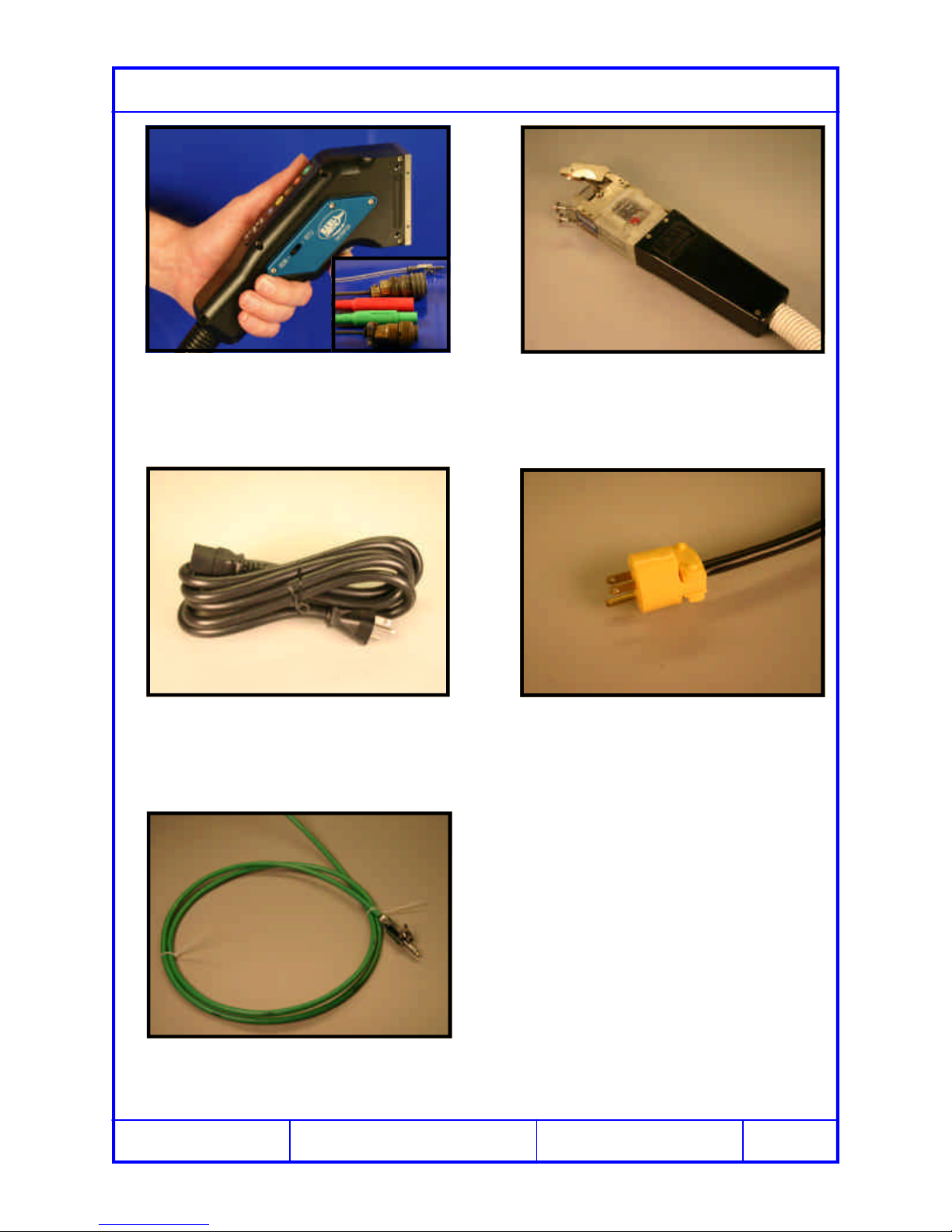
A welding head is required to operate
the EPS-2000 Power Supply. Above is
the Exel RDR-05 Rotor Driver.
The line cord provided is 20 amp rated
for 250 volt service.
The EPS-2000 Power Supply can oper-
ate Arc Machines orbital welding heads
as well.
A source of purge for the power supply
is required. Use the purge connector
provided.
It may be necessary to cut off the plug
provided on the line cord and replace it
with one suitable for the outlet intended.

Page 6
C Copyright 2005 Exel Orbital
All Rights Reserved
1.2.
3.4.
5.6.
Power Supply Hook Up
Start by inserting the A/C line plug into
power ranging from 85 to 265 volts and
from 47 to 63 hertz single phase.
Connect the power, ground, motor, gas
and remote (if applicable) of the welding
head to the power supply.
Chapter 1 Start Up
Notes:
1. The EPS-1000 does not require a
dedicated circuit.
2. Power Input: 85 to 265 volts and
47 to 63 hertz.
3. Purge Input: 15 to 80 psi or 100
to 530 Kpa.
Above is a view of the back of the EPS-
2000 Power Supply with all necessary
connectors visible.
Connect the Argon or mixed gas purge
inlet from the source to the power sup-
ply.

Page 7
C Copyright 2005 Exel Orbital
All Rights Reserved
1.2.
3.4.
5.6.
Power-Up
Turn the main power switch on.
Chapter 1 Start Up
The Main Screen will appear on the touch
screen. Select the desired Language then
touch any spot on the screen to continue.
The Library Screen above appears so
that a weld schedule may be created or
loaded from memory.
If Password protection selected enter
that password here.
1
2

Page 8
C Copyright 2005 Exel Orbital
All Rights Reserved
1.2.
3.4.
5.6.
C Copyright 2001 Exel Orbital Systems All Rights Reserved
EPS-2000 Power Supply
Chapter2,Libraryand Memory
Chapter2,Libraryand Memory
Chapter2,Libraryand Memory
Version 1.11.01
Revision Date: June 2005
Page 9
C Copyright 2005 Exel Orbital
All Rights Reserved
1.2.
3.4.
5.6.
Loading a Weld Schedule from the Main Memory
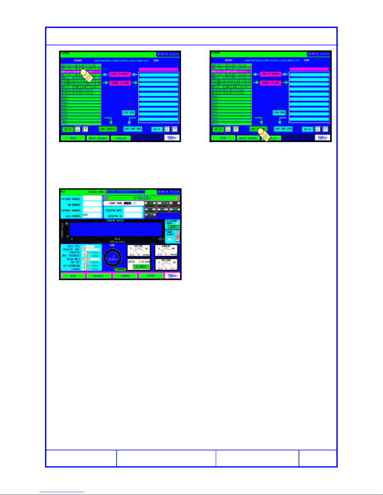
Select the desired weld schedule from
the Main Memory in the left column. Select Load Schedule.
The selected weld schedule appears on
the screen.

Page 10
C Copyright 2005 Exel Orbital
All Rights Reserved
1.2.
3.4.
5.6.
Loading a Weld Schedule from the CF Card
Orient the CF Card as shown. Insert the CF Card, being sure that it is
seated completely into the slot. The
eject button should pop up.
Eject
Button
Touch the VIEW CARD button and all
weld schedules in the card will be dis-
played in the right column.
Select the desired schedule and the
name will appear in the pink window
above the right column.
Touch LOAD FROM CARD and the weld
schedule will load
Page 11
C Copyright 2005 Exel Orbital
All Rights Reserved
1.2.
3.4.
5.6.
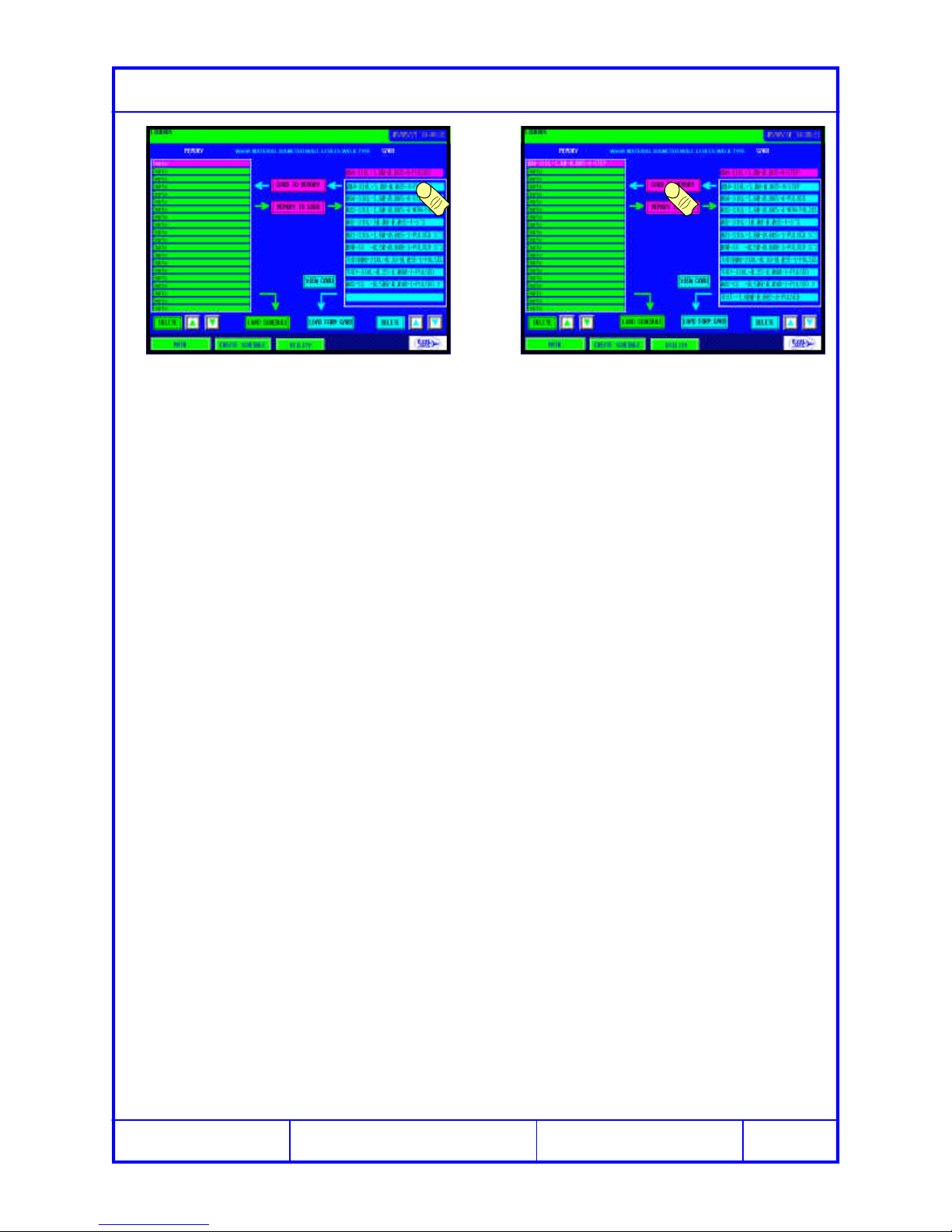
Moving a Weld Schedule from CF Card to Main Memory
Select the desired weld schedule to
transfer to main memory and it will ap-
pear in the pink window.
Select CARD TO MEMORY and the
weld schedule will be copied to the Main
Memory in the left column.
Page 12
C Copyright 2005 Exel Orbital
All Rights Reserved
1.2.
3.4.
5.6.
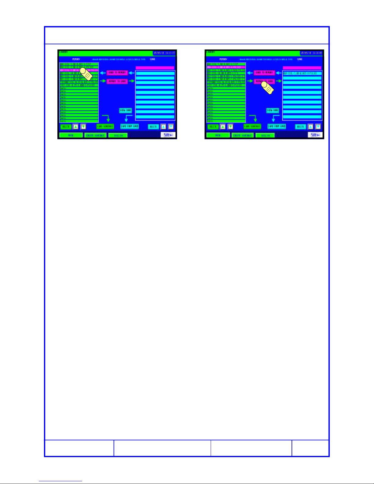
Moving a Weld Schedule from Main Memory to CF Card
Select the desired weld schedule to
transfer to the CF Card. Select MEMORY TO CARD and the
weld schedule will be copied to the CF
Card in the right column.
Page 13
C Copyright 2005 Exel Orbital
All Rights Reserved
1.2.
3.4.
5.6.
C Copyright 2001 Exel Orbital Systems All Rights Reserved
EPS-2000 Power Supply
Chapter3,CreateaWeld
Chapter3,CreateaWeld
Chapter3,CreateaWeld
Schedule,
Schedule,
Schedule,
Version 1.11.01
Revision Date: June 2005
Page 14
C Copyright 2005 Exel Orbital
All Rights Reserved
1.2.
3.4.
5.6.
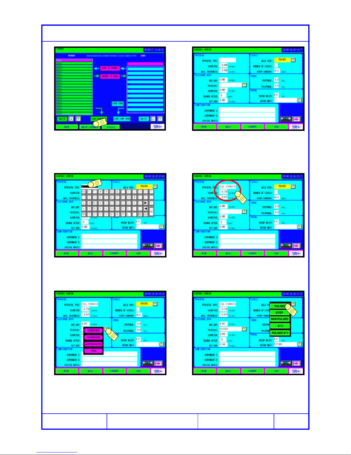
Creating a Weld Schedule -4 Level Weld
From the LIBRARY screen touch CRE-
ATE SCHEDULE. The above screen appears.
Enter the Material Type that will be
welded by touching the field and using
the QWRTY keypad that appears.
Fill in all the Material Fields.
Enter the Electrode Data and select the
electrode material from the pull down
menu. CHANGE AFTER alarms the op-
erator to change the electrode.
In the Levels category select the Weld
Type to be made.

Page 15
C Copyright 2005 Exel Orbital
All Rights Reserved
1.2.
3.4.
5.6.
Creating a Weld Schedule -4 Level Weld
After entering the data on the first screen
push the right arrow to move to the sec-
ond Schedule Screen
The above screen appears.
Enter Level 1 data and click UPDATE
GRAPH, both the polar and linear graph
of time, current and rotation are shown.
With a multi level weld it is convenient to
click the fill button to copy Level 1 infor-
mation to all subsequent levels.
Level 2 contains the same information as
level 1. Change the relevant field, in this
case 41 High amps. UPDATE GRAPH.
1
2
1
2
1
2
Edit Level 3 in the same manner as
Level 2 and UPDATE GRAPH to con-
form changes.

Page 16
C Copyright 2005 Exel Orbital
All Rights Reserved
1.2.
3.4.
5.6.
Creating a Weld Schedule -4 Level Weld
Edit Level 4 and UPDATE GRAPH. Enter a Down Slope and UPDATE
GRAPH. The 4 Level Pulsed Weld
Schedule is now complete.
1
212
To save the newly created weld sched-
ule touch SAVE. The Library Menu appears in Save As
mode. Displaying a default name in the
Schedule Name field.
Click SAVE TO MEMORY to save the
schedule in internal memory or SAVE
TO CARD to save to the CF Card.
If the default name is undesired touch
the SCHEDULE NAME field and a
KWRTY keypad appears to rename.

Page 17
C Copyright 2005 Exel Orbital
All Rights Reserved
1.2.
3.4.
5.6.
Creating a Weld Schedule -S3
In SCHEDULE SCREEN 1 select
PULSED S3as the Weld Type. When PULSED S
3is selected, notice
that Number of Levels shows INF. This
denotes that there are infinite levels.
Referring back to the multi-level weld de-
veloped on the previous pages, use the
settings for Level 1 and Level 4
Input Level 1 High amps for Point 1 and
Level 4 High amps for Point 2. Time is
the total of Level 1,2,3 & 4 time from the
Multi-Level weld.
Lev Time High Low Freq % High
11.9 42 10.5 650
21.9 41 10.5 650
31.9 40 10.5 650
41.9 38 10.5 650
Speed
8
8
8
8The S3Weld is complete
Note: Below are the values en-
tered for a 4 Level weld for 1/4” di-
ameter, .035 wall 316L Stainless
Steel.

Page 18
C Copyright 2005 Exel Orbital
All Rights Reserved
1.2.
3.4.
5.6.
Viewing or Modifying a Schedule
From the WELD Screen touch the
SCHEDULE button Enter the Programmer Password which
gives access to the weld schedule. See
Pass Words in the Utility Section.
The first screen to appear is Schedule
Screen 1. Click the Right Arrow to move
to Schedule Screen 2
Click the Left Arrow to move back to
Schedule Screen 1

Page 19
C Copyright 2005 Exel Orbital
All Rights Reserved
1.2.
3.4.
5.6.
C Copyright 2001 Exel Orbital Systems All Rights Reserved
EPS-2000 Power Supply
Chapter4,Making AWeld
Chapter4,Making AWeld
Chapter4,Making AWeld
Version 1.11.01
Revision Date: June 2005

Page 20
C Copyright 2005 Exel Orbital
All Rights Reserved
1.2.
3.4.
5.6.
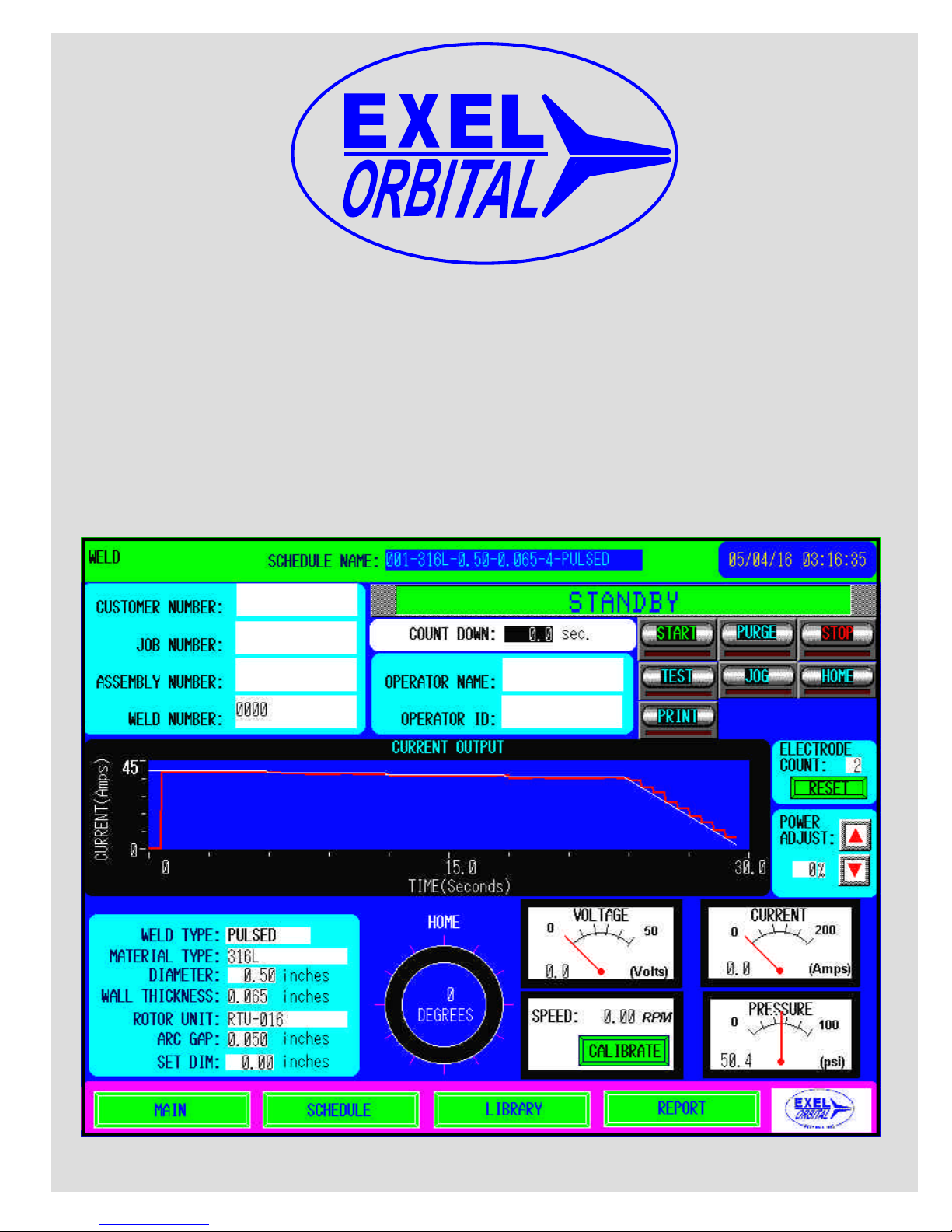
Weld Tracking Information
When a weld schedule loads there are
several fields that can be filled which al-
low tracking of a weld in the REPORT.
Touch the field where information is to
be entered and a QRTY keypad appears
Press ENTER when complete and the
QRTY keypad disappears. Continue filling in all remaining fields.
This information will now appear on the
Weld Report making tracking easier.
Note:
1. To open or create a weld sched-
ule see Library and Memory
Library and Memory
Library and Memory or Cre-
Cre-
Cre-
ate a Weld Schedule
ate a Weld Schedule
ate a Weld Schedule
Table of contents


