exemys EGW1-IA3-MB User manual

EGW1-IA3-MB User’s Manual Exemys
www.exemys.com Rev. 11

EGW1-IA3-MB User’s Manual Exemys
www.exemys.com Rev. 11
Exemys Products are in constant evolution to satisfy our customer needs.
For that reason, the specifications and capabilities are subject to change without prior notice.
Updated information can be found at www.exemys.com
Copyright © Exemys, 2007. All Rights Reserved.

EGW1-IA3-MB User’s Manual Exemys
www.exemys.com Rev. 11
INDEX
INDEX _________________________________________________________________________ 3
1
INTRODUCTION _________________________________________________________________ 5
1.1 Purpose of the manual __________________________________________________________ 5
1.2 Product Overview _______________________________________________________________ 5
1.3 Ordering Codes _________________________________________________________________ 6
1.4 Technical Specifications ___________________________________________________________ 6
2
INSTALLATION _________________________________________________________________ 7
1.5 Connecting the power supply ______________________________________________________ 7
1.6 Terminal Block Connection ________________________________________________________ 7
1.7 Serial Port Wirings _______________________________________________________________ 8
1.7.1 RS-232 ports wiring ____________________________________________________________________ 8
1.7.2 RS-485 port wiring ____________________________________________________________________ 9
1.8 LEDs Indicators _________________________________________________________________ 9
3
CONFIGURATION AND OPERATION _________________________________________________ 10
3.1 Network Configuration __________________________________________________________ 10
3.2 Configuration webpage __________________________________________________________ 11
4
OPERATION MODES ____________________________________________________________ 12
4.1 Modbus TCP to Modbus Serial _____________________________________________________ 12
4.1.1 ENRON _____________________________________________________________________________ 13
4.2 Modbus Serial to Modbus TCP _____________________________________________________ 14
4.2.1 Exceptions __________________________________________________________________________ 15
4.3 TCP to Transparent Serial Converter _________________________________________________ 16
4.4 Parameter common to all Modes ___________________________________________________ 17
4.4.1 Modbus write commands protection _____________________________________________________ 18
4.4.2 RTS terminal control (for serial radio modems) _____________________________________________ 19
5
ADVANCED USAGE MODES _______________________________________________________ 20
5.1 Modbus Multiplexer, TCP to Serial and Modbus Serial to Serial ________________________ 20
5.2 Combination: Modbus Serial-TCP and Modbus TCP-Serial ________________________________ 22
5.3 Transparent Mode - Connection with Serial Port Redirector _______________________________ 23
5.4 Internal Memory – Interchange between Masters_______________________________________ 24
6 MONITORING AND STATISTICS ____________________________________________________ 25
7
ADVANCED ___________________________________________________________________ 27
8
ADMINISTRATOR SETTINGS _______________________________________________________ 29
8.1 Password ____________________________________________________________________ 29
8.2 Reset _______________________________________________________________________ 29
8.3 Factory Reset _________________________________________________________________ 29
8.4 Firmware Upgrade______________________________________________________________ 29
9
SNMP _______________________________________________________________________ 31

EGW1-IA3-MB User’s Manual Exemys
www.exemys.com Rev. 11
9.1 Configuration and Operation ____________________________________________________ 31
9.2 MIB ________________________________________________________________________ 31
10
INPUTS AND OUTPUTS _________________________________________________________ 32
10.1 Configuration and Control ______________________________________________________ 32
10.2 Features, consumption and connection ______________________________________________ 32
10.2.1 Digital Inputs _____________________________________________________________________ 32
10.2.2 Digital Outputs ____________________________________________________________________ 33
10.3 Monitoring ___________________________________________________________________ 34
10.4 Modbus for Inputs and Outputs ____________________________________________________ 34
A. EXEMYS DEVICE LOCATOR _______________________________________________________ 35
B. MODBUS STATISTICS ___________________________________________________________ 37
C. COMMAND CONSOLE __________________________________________________________ 39
D.MODBUS ENRON SLAVE _________________________________________________________ 41
E. FACTORY SETTINGS ____________________________________________________________ 42
F. DIN RAIL MOUNTING ___________________________________________________________ 43

EGW1-IA3-MB User’s Manual Exemys
www.exemys.com Rev. 11
1 INTRODUCTION
1.1 Purpose of the manual
This manual provides the instructions for easy and quick installing and operating of the EGW1-IA3-MB.
The manual starts with a general description of the product, following the instructions for the correct
hardware installation. Configuration and operation of the device is detailed below.
Acronym Description
ARP
Address Resolution Protocol
BPS
Bits per second
HTTP
Hypertext Transfer Protocol
IP
Internet Protocol
LAN
Local Area Network
PC
Personal Computer
TCP
Transmiss
ion Control Protocol
DHCP
Dynamic Host Configuration Protocol
GND
Ground (Reference)
1.2 Product Overview
EGW1-IA3-MB is a Modbus TCP to Modbus Serial converter and vice versa.
It allows communication over Ethernet, with devices like alarm panels, HMI (Human-Machine-Interface)
software, PLCs or any device that has a serial interface and Modbus communication protocol (ASCII or
RTU).
EGW1-IA3-MB is the interface between serial communication devices and Ethernet communication
devices, acting as a two-way converter.
EGW1-IA3-MB is then, a complete solution for Ethernet connectivity of devices with serial port and
Modbus protocol.

EGW1-IA3-MB User’s Manual Exemys
www.exemys.com Rev. 11
1.3 Ordering Codes
The complete product ordering codes are:
Ordering Code Description
EGW1-1C0-00-IA3-MB-IS 1 configurable port RS-232 / RS-485 isolated / RS-422 isolated.
EGW1-1C0-10C-IA3-MB-IS 1 configurable port RS-232 / RS-485 isolated / RS-422 isolated +
10 configurable digital inputs / outputs.
EGW1-4B0-00-IA3-MB 4 configurable RS-232 / RS-485 ports.
1.4 Technical Specifications
Technical Specification
Network Protocols
Modbus TCP, TCP / IP, UDP / IP, DNS, HTTP, DHCP, ICMP, ARP, SNMP
Network Port
Ethernet 10 / 100 Mbps, RJ45 Connector
Serial Protocol
Modbus RTU, Modbus ASCII, Transparent
Serial Port
1 to 4 RS-232 / RS-485 / RS-422 depending on model Pluggable
Terminal Block connection
Supported devices
Any Serial Device RS-232 / RS-485 / RS-422 with Modbus or Modbus
TCP Protocol
Device Management
HTTP Server, password protected
RS-232 Serial Console
Firmware Update
From Web Page
Led Indicators
Status, Data / Link
Measurements
100mm x 22,5mm x 112mm (Height x Width x Length)
Power Supply
10 to 30 VDC
Consumption
12VDC 70mA/ 24VDC40mA
Temperatures
Operation Temperature: -15°Cto 65 °C
Storage Temperature: -40°Cto 75 °C
Warranty
1 Year
Technical Support Included

EGW1-IA3-MB User’s Manual Exemys
www.exemys.com Rev. 11
2 INSTALLATION
1.5 Connecting the power supply
EGW1-IA3-MB allows a power supply from +10 to 30 VDC. Positive power supply must be connected to
terminal N° 5 or N° 17 (depending on the model) and negative power supply to terminal No. 6 or No. 18
(depending on the model), as shown in the following figure:
1.6 Terminal Block Connection
According to the model of the EGW1-IA3-MB it will have:
EGW1-1C0-00-IA3-MB-IS EGW1-1C0-10C-IA3-MB-IS

EGW1-IA3-MB User’s Manual Exemys
www.exemys.com Rev. 11
EGW1-4B0-00-IA3-MB
1.7 Serial Port Wirings
1.7.1 RS-232 ports wiring
To connect the device RS232 serial port to PC serial port or any other serial device, it must be connected
as can be shown in the following figure. You should consider EGW1-IA3-MB is a DTE device, which
means it must cross wire with those of the PC.

EGW1-IA3-MB User’s Manual Exemys
www.exemys.com Rev. 11
1.7.2 RS-485 port wiring
In the EGW1-1C0-00-IA3-MB-IS andEGW1-1C0-10C-IA3-MB-IS to be able to use the device port on
RS485, the following connection must be made for correct operation:
1.8 LEDs Indicators
EGW1-IA3-MB has two LEDs indicators on the Ethernet connector, one green and one yellow. The yellow
one shows the connection to the network, while the green one indicates the status of incoming and
outgoing TCP connections.
Green Yellow Description
- Solid ON Looking for a DHCP server.
- ½ second on and ½ second off. Waiting serial console.
-
90% of a second off and the
remaining time on.
Device
has an IP address and a connection
bearer link. This is the normal operating state
- 10% of a second off and the
remaining time on.
It has no IP address and
cannot
find the DHCP
server. It will search the DHCP server for in 60
seconds.
-
Flashing very
fast
E
thernet cable d
isconnected
On
-
TCP connection
established
Flashing off
-
Da
ta t
ransmission or reception
.
Flashing alternatively
with Yellow LED
Flashing alternately
with the
Green LED Critical Failure. Contact technical support

EGW1-IA3-MB User’s Manual Exemys
www.exemys.com Rev. 11
3 CONFIGURATION AND OPERATION
3.1 Network Configuration
EGW1-IA3-MB configuration is done through a configuration web page connecting the device to the
Ethernet network on which it is going to work.
To access to the configuration web page, you must connect EGW1-IA3-MB to Ethernet network and
install
Exemys Device Locator
software.
Download the
Exemys Device Locator
:
http://www.exemys.com/beta/software/edl_setup.exe
Once the device is connected, this will search for a DHCP server to obtain an IP address automatically. We
will search for it using the
Exemys Device Locator
software, which allows us searching, identifying and
configuring the basic network parameters. The rest of the configuration is done from the configuration
web page of the device.
In case you do not have a DHCP server, the
Exemys Device Locator
will find the device with IP
address 0.0.0.0, as shown in the figure below.
If you do not have a DHCP server, give it an IP address using the
Exemys Device Locator
button or
using the methods explained in Appendix D.
The
Exemys Device Locator
buttons are:
Query Network: Searches for all connected EXEMYS devices on the same network.
Properties ...: Configuring Network Parameters (IP Address, Network Mask, and Gateway)

EGW1-IA3-MB User’s Manual Exemys
www.exemys.com Rev. 11
Configure...: Direct access to the configuration web page.
For more details on the
Exemys Device Locator
operation, see Appendix A.
3.2 Configuration webpage
Once the EGW1-IA3-MB has a valid IP address, you can access the web page to configure the other
parameters (If your web browser is configured to search for a proxy server, disable this option)
Type the EGW1-IA3-MB IP address in the address field of your browser or from the
Exemys Device
Locator
, press the Configure button.
If you configured a password, the computer will ask for it when entering the web page.
In this case, you must enter "admin" as the user and then the password that was set.
If you want to change it, you can do it from the Administrator menu
EGW1-IA3-MB User’s Manual Exemys
www.exemys.com Rev. 11
4 OPERATION MODES
When you enter the EGW1-IA3-MB configuration web page, you can configure the device to use it in one
of the following modes:
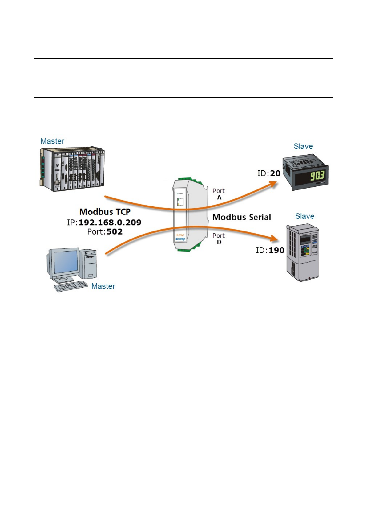
4.1 Modbus TCP to Modbus Serial
In this operation mode, the device role is translating “incoming” queries over the Ethernet interface in
Modbus TCP mode and sends them as "outgoing" queries to the Serial interface in Modbus Serial mode.
To use this mode, you must set the Modbus type to use (RTU or ASCII), the Modbus ID range of the
devices to be connected in that port, baud, parity, etc. in the selected Serial Port.
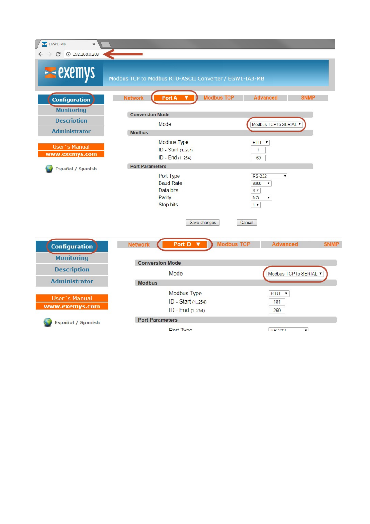
This configuration is done on the web page in Configuration / Port Tab. The figures below show a typical
configuration case, in Modbus TCP to SERIAL mode, with ID range from 1 to 60, for Port A and ID range
181 to 250 for Port D. With device IP address 192.168.0.209.
EGW1-IA3-MB User’s Manual Exemys
www.exemys.com Rev. 11
Device can receive up to 16 simultaneous incoming connections on Modbus TCP.
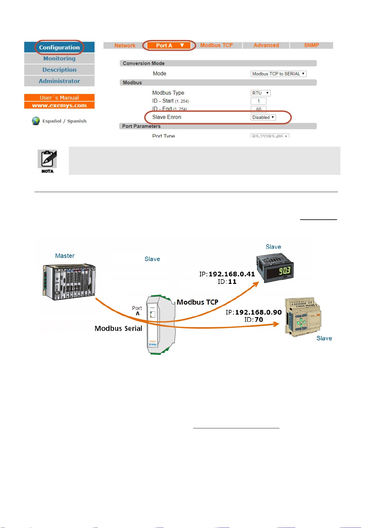
4.1.1 ENRON
From the firmware version 2.1, the EGW1-IA3-MB is added the feature conversion Modbus TCP to
Modbus ENRON.
This feature allows you to connect a Modbus Master, for example a SCADA, to a Modbus ENRON slave,
without needing to use the ENRON driver.
To use this mode, it must set the selected serial port in Modbus TCP to Modbus Serial Mode and enable
Slave Modbus ENRON option.
EGW1-IA3-MB User’s Manual Exemys
www.exemys.com Rev. 11
For more details and examples about Slave ENRON Modbus, see Appendix E.
4.2 Modbus Serial to Modbus TCP
In this operation mode, the device role is translating “incoming” queries through Serial interface in
Modbus Serial mode and sends them as "outgoing" queries to the Ethernet interface in Modbus TCP
mode.
To use this mode, you must set the Modbus type to use (RTU or ASCII), baud, parity, etc. in the selected
Serial Port. Besides, the range of IDs to be accessed and the IP address of the device to send the incoming
queries must be to set in the MODBUS TCP table.
This table has the capacity to handle up to 16 TCP connections.
The figures below show a typical configuration case, in Modbus Serial to Modbus TCP mode.

EGW1-IA3-MB User’s Manual Exemys
www.exemys.com Rev. 11
In the Modbus TCP Table, the ranges of IDs and the destination IP are added for each port configured in
Modbus SERIAL to TCP mode. In this example IDs 1 to 20 and 27 to 72 are configured, each with its
destination IP.
On devices with more than one serial port, each of them can be configured in Modbus SERIAL to TCP
mode independently.
4.2.1 Exceptions
You can enable or disable the "Exceptions" parameter, which enables the EGW1-IA3-MB to respond or
not to exceptions in case of communication errors. If the option is disabled the EGW1-IA3-MB will remain
silent before the errors, otherwise it will return an exception code:
0x0A- Road not available
- The message has ID of a device that is not configured in the MODBUS TCP table.

EGW1-IA3-MB User’s Manual Exemys
www.exemys.com Rev. 11
- Failure to open the TCP connection. The reasons for this error may be transient or
incorrect configuration.
0x0B- The remote device is not responding
- No response within the maximum message waiting time
(Message Response Time).
- Invalid message header received.
- The connection was closed while waiting for the answer.
4.3 TCP to Transparent Serial Converter
In this operation mode, EGW1-IA3-MB behaves like a serial server in TCP Server Mode.
In this mode the EGW1-IA3-MB will be listening and waiting for a client to establish a TCP connection.
Once this connection is established, all data received on the Ethernet interface will be transmitted to the
serial port and vice versa transparently, functioning as a TCP to RS-232 / RS-485 / RS-422 converter and
vice versa.
The port of this TCP connection will be informed on the web when selecting the using mode.
While the EGW1-IA3-MB is in Transparent mode it stops functioning as a Modbus TCP to
Modbus SERIAL converter

EGW1-IA3-MB User’s Manual Exemys
www.exemys.com Rev. 11
4.4 Parameter common to all Modes
The following parameters can be configured in the device serial port:
Parameter Options
COM Type
RS-232/RS-485
or
RS-232 - RS-485/RS-422
Baud Rate 300 to 115200 bps
Data Bits ASCII (7 - 8) / RTU (8)
Parity No / Even / Odd
Stop Bits 1 / 2

EGW1-IA3-MB User’s Manual Exemys
www.exemys.com Rev. 11
4.4.1 Modbus write commands protection
This feature is available since firmware 2.6
This feature will block the write commands issued by the Modbus master devices before sending them to
the slaves.
This will not apply to the built-in digital I/Os.
The commands that are blocked are the following:
0x05: Force Single Coil.
0x06: Preset Single Register.
0x0F: Force Multiple Coils.
0x10: Preset Multiple Regs.
0x15: Write General Reference.
0x16: Mask Write 4X Register.
0x17: Read/Write 4X Registers.
To enable this feature go to the serial port web page (Configuration / Port X).
The write commands protection will work on these modes:
Modbus TCP to Modbus Serial
Modbus Serial to Modbus TCP

EGW1-IA3-MB User’s Manual Exemys
www.exemys.com Rev. 11
4.4.2 RTS terminal control (for serial radio modems)
This feature is available since firmware 2.7
This feature allows the EGW1-MB-1C0-10C-IA3-IS and EGW1-MB-1C0-00-IA3-IS, to control the RTS
terminal to control serial radio modems.
To enable it, go to Port A web page and configure the RTS terminal logic, the time to wait to send the
data after turning the terminal ON, and the time to hold the terminal ON after sending the data.
The default values are 0 ms.

EGW1-IA3-MB User’s Manual Exemys
www.exemys.com Rev. 11
5 ADVANCED USAGE MODES
5.1 Modbus Multiplexer, TCP to Serial and Modbus Serial to Serial
In this advanced usage mode, the EGW1-4B0-00-IA3-MB, solves the problem of having a serial slave
being interrogated by a Serial Master (Modbus Serial-Serial) and a remote master, through Modbus TCP
(Modbus TCP-Serial).
Once the problem has been presented, to use this mode, the EGW1-4B0-00-IA3-MB must be configured
as follows:
A port, for example we will use Port A, configured in Modbus TCP to Modbus Serial mode and the
range of devices IDs with which we will communicate serially. In this way we establish the
Modbus TCP-SERIAL communication.
A port, for example we will use Port B, configured in Modbus Serial to Modbus TCP mode, but at
this time we will not set anything in the Modbus TCP table, as its use in 3.3.2.
In this way we establish the Modbus SERIAL-SERIAL communication, because if device does not find a
TCP connection loaded in the Modbus TCP table, it will look for if any Serial Port is configured in Modbus
TCP to SERIAL and when detecting at least one in This mode (in our case Port A), verifies that the
destination ID is included in the range that the Serial Port has configured, so, sends the query by the
found Serial Port and not by the TCP connection. In this way the Modbus Serial-Serial Mode is gotten.
NOTE: In this example, there are no values in the Modbus TCP table for the Port B, that’s why it works
Modbus Serial to MODBUS Serial mode.
Other manuals for EGW1-IA3-MB
1
Table of contents
Other exemys Media Converter manuals


