exemys EGW1-IA3-MB-DF1 User manual

EGW1-IA3-MB-DF1 – Modbus TCP a DF1 User’s Manual Exemys
www.exemys.com Rev. 1 1

EGW1-IA3-MB-DF1 – Modbus TCP a DF1 User’s Manual Exemys
www.exemys.com Rev. 1 2
Exemys Products are in constant evolution to satisfy our customer needs.
For that reason, the specifications and capabilities are subject to change without prior notice.
Updated information can be found at www.exemys.com
Copyright © Exemys, 2007. All Rights Reserved.

EGW1-IA3-MB-DF1 – Modbus TCP a DF1 User’s Manual Exemys
www.exemys.com Rev. 1 3
Page index
1 Introduction ________________________________________________________ 4
1.1 Purpose of the manual ________________________________________________ 4
1.2 General description. __________________________________________________ 4
1.3 Available models.____________________________________________________ 4
1.4 Technical specifications. _______________________________________________ 5
2 Installation ________________________________________________________ 6
2.1 Connecting the power supply ___________________________________________ 6
2.2 Terminal Block Connection _____________________________________________ 6
2.3 LEDs Indicators _____________________________________________________ 8
3 Configuration and operation ____________________________________________ 9
3.1 Network configuration. _______________________________________________ 9
3.2 Configuration web page. _____________________________________________ 10
3.3 Modbus TCP configuration ____________________________________________ 10
3.4 DF1 configuration __________________________________________________ 11
3.5 Translation Tables page. ______________________________________________ 13
4 Operating modes ___________________________________________________ 15
4.1 Modbus TCP a DF1 converter __________________________________________ 15
4.2 TCP to serial – Transparent mode _______________________________________ 17
5 Statistics _________________________________________________________ 19
6 Advanced configuration ______________________________________________ 20
6.1 Password. ________________________________________________________ 20
6.2 Reset ____________________________________________________________ 20
6.3 Factory Reset. _____________________________________________________ 20
6.4 Firmware update. ___________________________________________________ 20
A. DEVICE LOCATOR 22
B. MODBUS STATISTICS 24
C. COMMAND CONSOLE 25
D. PING-BASED METHOD FOR IP CONFIGURATION 27
E. CONFIGURING FLEXLOGIX AND CONTROLLOGIX PLCS 28
F. FACTORY SETTINGS 29
G. DIN RAIL MOUNTING 30

EGW1-IA3-MB-DF1 – Modbus TCP a DF1 User’s Manual Exemys
www.exemys.com Rev. 1 4
1 Introduction
1.1 Purpose of the manual
EGW1-MB-DF1 is a Modbus TCP to DF1 gateway. EGW1-MB-DF1 lets you gain access to a wide range of
industrial devices that talk DF1 protocol just by using Modbus TCP, a
de facto
standard in the industrial
field.
Acronym Description
ARP
Address Resolution Protocol
BPS
Bits per second
HTTP
Hypertext Transfer Protocol
IP
Internet Protocol
LAN
Local Area Network
PC
Personal Computer
TCP
T
ransmission Control Protocol
DHCP
Dynamic Host Configuration Protocol
GND
Ground (Reference)
1.2 General description.
EGW1-IA3-MB-DF1 is a Modbus TCP to DF1 converter.
It allows communication over Ethernet, with devices like alarm panels, HMI (Human-Machine-Interface)
software, PLCs to legacy DF1 devices.
1.3 Available models.
Part number Serial
Protocol
Ethernet
Protocol Serial Ports
EGW1
-
1044
-
MB
-
DF1
DF1
Modbus TCP
RS
-
232

EGW1-IA3-MB-DF1 – Modbus TCP a DF1 User’s Manual Exemys
www.exemys.com Rev. 1 5
1.4 Technical specifications.
Technical Specification
Network Protocols
Modbus TCP, TCP / IP, UDP / IP, DNS, HTTP, DHCP, ICMP, ARP
Network Port
Ethernet 10 / 100 Mbps, RJ45 Connector
Serial Protocol
DF1, Transparent
Serial Port
1 RS-232 on Pluggable Terminal Block connection
Device Management
HTTP Server, password protected
RS-232 Serial Console
Firmware Update
From Web Page
Led Indicators
Status, Data / Link
Measurements
100mm x 22,5mm x 112mm (Height x Width x Length)
Power Supply
10 to 30 VDC
Consumption
12VDC 70mA/ 24VDC40mA
Temperatures
Operation Temperature: -15°Cto 65 °C
Storage Temperature: -40°Cto 75 °C
Warranty
1 Year
Technical Support Included

EGW1-IA3-MB-DF1 – Modbus TCP a DF1 User’s Manual Exemys
www.exemys.com Rev. 1 6
2 Installation
2.1 Connecting the power supply
EGW1-IA3-MB-DF1 allows a power supply from +10 to 30 VDC. Positive power supply must be connected
to terminal N° 1 and negative power supply to terminal No. 2, as shown in the following figure:
2.2 Terminal Block Connection
EGW1-100-00-IA3-MB-DF1

EGW1-IA3-MB-DF1 – Modbus TCP a DF1 User’s Manual Exemys
www.exemys.com Rev. 1 7
To connect the device RS232 serial port to PC serial port or any other serial device, it must be connected
as can be shown in the following figure. You should consider EGW1-IA3-MB-DF1 is a DTE device, which
means it must cross wire with those of the PC.
To connec the device to a PLC’s serial port (Micrologix 1000) follow this diagram

EGW1-IA3-MB-DF1 – Modbus TCP a DF1 User’s Manual Exemys
www.exemys.com Rev. 1 8
2.3 LEDs Indicators
EGW1-IA3-MB-DF1 has two LEDs indicators on the Ethernet connector, one green and one yellow. The
yellow one shows the connection to the network, while the green one indicates the status of incoming
and outgoing TCP connections.
Green Yellow Description
- Continuously on Looking for a DHCP server.
- ½ second on and ½ second off.
Waiting for configuration ping and / or
waiting
serial console.
-
90% of a second off and the
remaining time on.
Device
has an IP address and a connection
bearer link. This is the normal operating state
- 10% of a second off and the
remaining time on.
It has no IP address and
cannot
find the DHCP
server. It will search the DHCP server for in 60
seconds.
- Flashing very fast
Lack of Ethernet
link
(Cable disconnected).
On
-
TCP connection set.
Flashing off
-
Transmission or reception of data
.
Flashing alternatively
with Yellow LED
Flashing alternately
with the
Green LED Critical Failure. Contact technical support

EGW1-IA3-MB-DF1 – Modbus TCP a DF1 User’s Manual Exemys
www.exemys.com Rev. 1 9
3 Configuration and operation
3.1 Network configuration.
EGW1-IA3-MB configuration is done through a configuration web page connecting the device to the
Ethernet network on which it is going to work.
To access to the configuration web page, you must connect EGW1-IA3-MB to Ethernet network and
install
Exemys Device Locator
software.
Download the
Exemys Device Locator
:
http://www.exemys.com/beta/software/edl_setup.exe
Once the device is connected, this will search for a DHCP server to obtain an IP address automatically. We
will search for it using the
Exemys Device Locator
software, which allows us searching, identifying and
configuring the basic network parameters. The rest of the configuration is done from the configuration
web page of the device.
In case you do not have a DHCP server, the
Exemys Device Locator
will find the device with IP
address 0.0.0.0, as shown in the figure below.
If you do not have a DHCP server, give it an IP address using the
Exemys Device Locator
button or
using the methods explained in Appendix D.
The
Exemys Device Locator
buttons are:
Query Network: Searches for all connected EXEMYS devices on the same network.

EGW1-IA3-MB-DF1 – Modbus TCP a DF1 User’s Manual Exemys
www.exemys.com Rev. 1 10
Properties ...: Configuring Network Parameters (IP Address, Network Mask, and Gateway)
Configure...: Direct access to the configuration web page.
For more details on the
Exemys Device Locator
operation, see Appendix A.
3.2 Configuration web page.
Once the EGW1-IA3-MB has a valid IP address, you can access the web page to configure the other
parameters (If your web browser is configured to search for a proxy server, disable this option)
Type the EGW1-IA3-MB IP address in the address field of your browser or from the
Exemys Device
Locator
, press the Configure button.
If you configured a password, the computer will ask for it when entering the web page.
In this case, you must enter "admin" as the user and then the password that was set.
If you want to change it, you can do it from the Administrator menu
3.3 Modbus TCP configuration
On this web page you can configure
1. Network parameters: EGW1-MB-DF1 default IP address is 0.0.0.0. Thus, unless you set a static IP
address, it will attempt to get an IP address from a DHCP server. The device tries to negotiate an
IP address with a DHCP server for a maximum period of 10 seconds. If a DHCP server fails to
answer in that period, EGW1-MB-DF1 will show an error code through the frontal LEDs (refer to
Appendix D for a list of error codes) and then it will retry other DHCP negotiations every 60
seconds. This process will be repeated until the negotiation succeeds.
Changing these network parameters through the web has the same effect as configuring the IP
address, Netmask and Gateway using EDL. Please note that if you make any change to these

EGW1-IA3-MB-DF1 – Modbus TCP a DF1 User’s Manual Exemys
www.exemys.com Rev. 1 11
values, the web service (actually every network connection) will only be available with the newer
settings and after the device is reset (software reset takes about three seconds).
2. TCP Keep Alives: This is a common mechanism used to early detect broken TCP connections. If
enabled (by setting this parameter to a value bigger than zero) the device will send a frame to those
Modbus TCP masters that do not generate requests for a period longer than this value. If a master
answers the keep alive, no action is taken on its connection. However, should this query fail, the link
will be considered as broken, thus EGW1-MB-DF1 will abort the failing connection.
3. TCP Buffering.: When a Modbus TCP request arrives to the device while another is being served, two
decisions can be taken, according to this parameter: discard the latest request (Disabled) or buffer the
request (Enabled). Note that in case that you buffer requests, the delay between requests and replies may
result longer than expected, since other command(s) could be already queued. In other words, in heavy
loaded environments, you might notice timeouts in your Modbus TCP masters.
4. Embedded Slave: The device has a Modbus TCP slave that can receive requests from an external
master to get operation statistics. (See Apendix B for further details).
You may disable the embedded slave if you do not need you are not interested in statistics reports via
Modbus TCP requests. If enabled, the embedded slave receives and processes external requests issued to
the Unit ID configured.
5. Modbus Exceptions: The term exception refers to the mechanism defined by the Modbus specification
to signal error conditions, such as polling to an invalid address or polling too many locations in memory.
Disable this feature if you do not want to receive exceptions upon a failure.
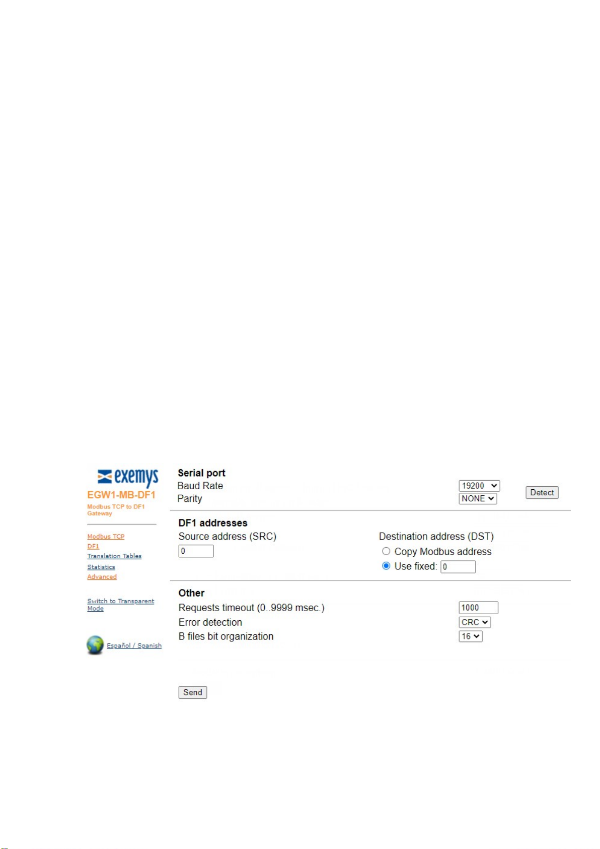
3.4 DF1 configuration
On this web page you can configure:
1. Baud Rate and Parity: It is possible to set these parameters manually, that is, without detecting these
link parameters by clicking on the Detect button. These fields could be filled by hand if you want to set
the serial parameters before the PLC is actually connected.
EGW1-IA3-MB-DF1 – Modbus TCP a DF1 User’s Manual Exemys
www.exemys.com Rev. 1 12
2. DF1 Source Address: DF1 frames define Source (SRC) and Destination (DST) addresses, corresponding
to the stations that want to exchange data. While these parameters seem to be important, most
implementations do not take care of its values. This is because DF1 is commonly used as a point-to-point
protocol, where only two stations are connected to the wire. As a consequence, addresses are not a
matter. However, there are two associated protocols, called Data Highway (DH) and Data Highway +
(DH+), which provide communication paths among many stations. In these cases, addresses are a must.
This field, as well as the one described below, provide compatibility for those protocols, when interfacing
the EGW1-MB-DF1 with a DH/DH+ network, using an adapter.
3. DF1 Destination Address: This field defines the Destination Address to be used when issuing DF1
requests. You can choose to use a fixed address, or copy the same address received at the Modbus side.
Again, if running legacy DF1, this field and the one described above do not need to be changed.
4. Requests Timeout: This timeout defines the round trip time, measured between the incoming request
is removed from the TCP/IP buffer and the appropriate answer is ready to be sent back to the Modbus
TCP master. When the buffering feature is enabled (see TCP buffering in the previous page), the queue
time is not considered a part of this time. This timeout will only run when a new frame is processed. In
other words, when the load is heavy enough to queue frames, you might notice timeouts in the Modbus
TCP master(s), but not exceptions due to time exceeded. Those timeouts are the ones configured at each
master and not the one provided in this field.
5. Error Checking: Two methods are provided by the DF1 specification to detect frame errors, BCC and
CRC. BCC is a one-octet field appended to a DF1 frame. It contains a checksum of many bytes contained
in the message. By the other hand, the CRC, which stands for Cyclic Redundancy Check and is two-octets
long, is a more robust method in the sense that it will detect more errors than BCC. This setting must be
coherent with that configured in the PLC: if the PLC is set to BCC you have to set EGW1-MB-DF1 to use
BCC and vice versa.

EGW1-IA3-MB-DF1 – Modbus TCP a DF1 User’s Manual Exemys
www.exemys.com Rev. 1 13
3.5 Translation Tables page.
In these sections, some basic aspects on Modbus TCP and DF1 protocols are outlined.
Modbus TCP data are classified into four types, such as defined in Modbus ASCII/RTU.
These areas are known as:
Input Registers
Holding Registers
Input Status
Coil Status
Input Registers and Holding Registers are 16-bit words, while Input Status and Coils Status are mapped to
discrete 1-bit data. By the other hand Input Registers and Input Status are read-only areas, used to read
input data such as digital inputs and statistics. Holding Registers and Coils Status areas may be both read
and written.
PLCs compatible with DF1 protocol usually map addressable data into Files and Elements. A group of
data with similar characteristics is called a File and each datum within a File is an Element. Files are
organized into File Types, according to their different purposes. For example, N Files are used to store 16-
bit integers, B Files store bit variables and the O File is used to write a value to a PLC output. Each File is
associated to a unique File Number.
1. N Files: This table provides the capability to map N Files, which usually store program variables.
Up to thirty-two N Files will be allowed, thus covering a wide range of typical situations. Each Element in
the File is mapped into Holding Registers, allowing both reads and writes (16 bits wide). The only entry to
know before adding an N File is its File Number. (Usually, File Number 7 is associated with a default N
File, though other N Files could be configured using the application software provided with your PLC).
2. B Files: This table stores the Bit File, used to keep 1-bit variables. Up to two B Files can be added
to the table. This might seem a scarce resource, but actually it is not. Have in mind that each 1-bit
location is mapped to a different Modbus TCP Coil Status, thus consuming the addressing space very
quickly. Also consider that these two B Files lets you map 8192 individual bits, providing an adequate
capability for most applications.
3. S File: This is the only fixed (non-configurable) table. The mapping (Input Registers 30192-30447)
provides reads of internal statistics.
In order to work accurately, I/O expansion boards and other Files in general have to be configured with
the application software provided by the PLC vendor. Otherwise, the Files will be unavailable to the
EGW1-MB-DF1, which will return Modbus exceptions (if enabled) upon unsolved requests. Contact you
dealer for specific information about your PLC and configuration.
Many newer PLCs (such as FlexLogix and ControlLogix) do not provide (as a factory default) compatibility
with the type of request issued by the EGW1-MB-DF1. However, they do provide a mechanism to make
them downwards-compatible with other PLCs and with the EGW1-MB-DF1. Please refer to Appendix E if
you are attempting to connect one of the PLCs above to the EGW1-MB-DF1.
You can insert a record into an intermediate position by selecting the appropriate row. After insertion,
rows below the insertion point will be shifted downwards. If you insert erroneous data, delete the record
by selecting it and then clicking on Delete.

EGW1-IA3-MB-DF1 – Modbus TCP a DF1 User’s Manual Exemys
www.exemys.com Rev. 1 14
Modbus TCP address boundaries are assigned automatically by the device. For example, if you insert a
record into the first position of the N Table, the first Element is mapped to Holding Register 40192, the
second Element is mapped to Holding Register 40193 and so on. Thus, you will have to configure your
Modbus TCP master(s) to make polls within those boundaries in order to obtain valid answers.

EGW1-IA3-MB-DF1 – Modbus TCP a DF1 User’s Manual Exemys
www.exemys.com Rev. 1 15
4 Operating modes
4.1 Modbus TCP a DF1 converter
Protocol conversion is based on tables that store the mapping between incoming requests (using
Modbus TCP protocol) and PLC data areas. Table translation applies for internal memory, but is not used
for Inputs/Outputs.
As a factory default , many newer PLCs (such as FlexLogix and ControlLogix) do not provide compatibility
with the type of request issued by the EGW1-MB-DF1. However, they do provide a mechanism to make
them downwards-compatible with other PLCs and with the EGW1-MB-DF1. Please refer to Appendix E if
you are attempting to connect one of the PLCs above to the EGW1-MB-DF1.
Henceforth, a real situation is proposed. It might differ slightly from your actual configuration, though we
think of an study case as the best way to get in touch with your new gateway.
There is PLC that runs a program. We want to make some data available to one Modbus TCP master by
means of the EGW1-MB-DF1. These boards have the following I/O capacities:
Table 1 - IO Capacity
Module Feature Capacity
1 16 Digital Inputs 1 word
2 32 Digital Outputs 2 words
3 4 Analog Outputs 4 words
4 32 Digital Inputs 2 words
It is desired to access not only I/O data, but it is also important to read some words, contained in two N
Files (File Numbers 7 and 10) and some read/write bit variables, contained in one B File, whose File
Number is 3. First, we check the internal tables are clean, by clicking on the Translation Tables link,
located on the left frame.

EGW1-IA3-MB-DF1 – Modbus TCP a DF1 User’s Manual Exemys
www.exemys.com Rev. 1 16
Figure 1 - Translation Tables page
The page is divided into three sections, the first three are user-configurable, while the last one is fixed.
N section lets you add and remove N Files. Each element in an N File is 16-bits wide.
B section lets you add and remove B Files. Each element in a B File is 1 bit wide.
S section stands for the S File, the area where many PLCs store statistics data.
Going on with the example, after inserting the proper data, the page will look like it is shown in Figure 7.
Figure 2 - Translation Tables filled with PLC information

EGW1-IA3-MB-DF1 – Modbus TCP a DF1 User’s Manual Exemys
www.exemys.com Rev. 1 17
Input and outputs modules connected to the PLC do not require any further configuration in the EGW1-
MB-DF1. In order to access the modules, the end user will have to issue appropriate Modbus requests,
thus the protocol converter will translate them into DF1 commands which can be understood by the PLC.
The mapping between Modbus and DF1 protocol for Input/Output modules is straightforward. It is
summarized in the following rules:
Input modules can be read through Inputs Status or Input Register.
Output modules can be read through Coil Status or Holding Register.
Each Holding Register or Input Register is associated to one word (16 bits). Thus, each word
contained in a module is assigned to one Modbus location, either Holding Register or Input
Register (generically, one “Register” location).
Each Coil Status or Input Status is associated to one bit. Thus, each bit contained in a module is
assigned to one Modbus location, either Coil Status o a Input Status (generically, one “Status”
location).
The multiple coils write command only allows a write to a single coil.
Modules with less than one word use one complete Modbus “Register”.
Requests to “Register” locations up to address 64 are assumed to be requests for the modules.
Requests to “Status” locations up to address 1024 are assumed to be requests for the modules.
The modules will be addressed as shown in the following table, according to the rules above.
For example:
To read output 20 in module 2, ask for Coil Status 00021.
To read word 3 in module 3, ask for Input Register 30004
The device can handle up to 8 simultaneous Modbus TCP connections.
4.2 TCP to serial – Transparent mode
In this mode the EGW1-IA3-MB-DF1 will work a serial server in “server” mode. It will wait for an
incoming TCP connection and will send all the received data to the RS232 port and vice versa.
This mode will use port 10000.
While in transparent mode the EGW1-IA3-MB-DF1
will stop working as Modbus TCP to DF1
converter.
Module Coil Status Input Status Holding Register Input Register
1 10001-10016 30001-30001
2 00001-00032 40001-40002
3 10017-10080 30002-30005
4 00033-00064 40003-40004

EGW1-IA3-MB-DF1 – Modbus TCP a DF1 User’s Manual Exemys
www.exemys.com Rev. 1 18

EGW1-IA3-MB-DF1 – Modbus TCP a DF1 User’s Manual Exemys
www.exemys.com Rev. 1 19
5 Statistics
EGW1-MB-DF1 keeps an internal statistic, related to successful and failed transactions. Think of this
feature as a powerful tool when debugging your system. This service is available not only through this
web page, but it also could be monitored through the embedded Modbus TCP slave

EGW1-IA3-MB-DF1 – Modbus TCP a DF1 User’s Manual Exemys
www.exemys.com Rev. 1 20
6 Advanced configuration
6.1 Password.
The web page and settings by Exemys Device Locator can be protected with a password. This
password can also be set from the serial command console (see Appendix C).
It only supports alphanumeric characters. User which asked to type the password is "admin".
To delete the access key, just save an empty password.
6.2 Reset
If necessary, the EGW1-IA3-MB-DF1 can be restarted. In this way all your connections will be
closed, and all your tasks will begin again as if it had just device energized
6.3 Factory Reset.
The User can return the device to its original factory settings. This option can be executed from the
web page or from the serial command console
6.4 Firmware update.
Device firmware can be updated in case of new versions with improvements.
Pressing Update button, web page will ask to select the update file (it must start with EGW1 and end
with .BIN). Then press the Download button. Through informational messages you can follow the update
process.
Device will restart and be ready to operate again after uploading.
Table of contents
Other exemys Media Converter manuals


Popular Media Converter manuals by other brands

AJA
AJA Hi5-4K Installation and operation guide

PIKO
PIKO 56424 quick start guide

Leonton
Leonton MET2-0201-M Series user manual

Snell Advanced Media
Snell Advanced Media MV-800 Quick setup guide

AudioEngine
AudioEngine D3 Premium 24-Bit DAC quick start guide

CircuitWerkes
CircuitWerkes Sub-03 Technical manual


