Luxman DA-200 User manual

Owner`s
Manual

Contents
Precautions ············································································································· 1
Features of This Unit································································································ 2
Names and Functions······························································································ 4
Connections ············································································································ 8
Operations············································································································· 10
Block Diagram······································································································· 12
Specifications ········································································································ 13
Before Asking for Repair Services·········································································· 14

USB D/A CONVERTER DA-200
1
Precautions
Installation place
• Choose a stable place near the devices that are to be used
in combination with this unit.
• Do not install this unit near a television or color monitor.
Keep this unit away from such devices as cassette decks
that are subject to magnetism.
Avoid the following locations for
installation.
• Locations exposed to direct sunlight
• Places subject to humidity and with less ventilation
• Places where are extremely hot or cold
• Places subject to strong vibration
• Places subject to dust
• Places subject to oil, steam, and heat (such as kitchens)
To avoid heat emission
Do not place this unit on such device as an amplifier that may
emit heat. If the unit is installed on a rack, install the unit as
distantly as possible from where the amplifier is installed so
as to avoid heat emission from the amplifier and other audio
devices.
Power off this unit when it is not used.
Depending on the condition of radio waves emitted during
television broadcasting, interference fringes may appear on
the television monitor, but that is not a malfunction. In such
a case, power off the unit. There may also be a case where
noises are heard on the radio due to radio wave interference.
Notice when handling optical digital cables
• Do not fold the cables. For storage, wind each cable to
make a coil whose diameter is approx.15 cm or larger.
• For connection, insert the cable connectors firmly into the
terminals of this unit and the other device.
• Use the cables whose each length is 3 m or less.
• When the cable connectors get dusty, wipe the dust away
with a dry soft cloth before inserting into the terminals.
Cleaning
• Usually, wipe the unit with a dry soft cloth. When the dirt
is hard to remove, dip soft cloth in detergent diluted 5 or 6
times with water, wring it well, and remove contaminants.
Then, remove the moisture with dry cloth.
• Do not use a solvent like alcohol, benzine, thinner, or pes-
ticide because such a substance can damage the exterior.
In addition, do not let this unit contact a rubber or plastic
form for a long time. That may damage the cabinet surface
of the unit.
• When using a chemical cloth for cleaning, read the caution
provided with the chemical cloth product.
• Before cleaning, unplug the power cord from the AC outlet.
Precautions in connecting with other
components
When connecting this unit to input devices such as a CD
player, an SACD player, a tuner, and a recorder, be sure to
turn off the power of this unit and all other connected devices.
Failure to observe this may generate a strong noise resulting
in speaker damage or cause a malfunction.
The pin-plug to be inserted in each input terminal of this unit
shall be pushed in firmly. If the grounding terminal is inad-
equately connected, noises including hum may be generated,
resulting in an adverse S/N ratio.
Repair and adjustment
When repairs or adjustments are needed, please ask the
dealer where you bought the unit.

2
Features of This Unit
Compact chassis design
This unit is a 2-channel PCM D/A converter that has a com-
pact body as small as B4-paper size.
USB input that is applicable to
96 kHz / 24 bit
Introduction of a B-type USB input terminal that allows the
input of USB digital audio signal from a PC/Mac.
Circuits whose grade is equivalent to D-05
High-performance circuits, equivalent to those of the SACD
player D-05, are used for the peripheral circuit of DAC and the
analog output amplifier.
DD converter function
All the digital inputs including USB are converted into digital
outputs as the S/PDIF signals.
Built-in headphone amplifier
This unit is equipped with a high-grade headphone amplifier
circuit.
Built-in pre-amplifier circuit
This unit is equipped with a newly-designed pre-amplifier cir-
cuit that is effective for unbalanced variable level outputs.
Balance output
This unit is equipped with XLR balance output terminals with
full-fledged balanced- structure circuits that are effective for
digital inputs.
PCM1792A manufactured by Burr-Brown
For the DAC chip, this unit applies PCM1792A manufactured
by Burr-Brown that has been used for the Luxman new D-
series SACD players.

USB D/A CONVERTER DA-200
3
Compatibility with high-resolution formats
This unit has the compatibility with digital inputs of 32 kHz to
192 kHz (32 kHz to 96 kHz for USB) sampling frequencies
and numbers of quantization bits of 16 bit, 20 bit, and 24 bit
(16 bit, 24 bit for USB).
Built-in sampling rate converter
Digital input signals are processed for up-sampling at the time
of D/A conversion.
Jitter reduction function
The dedicated clock unsynchronized with inputs can reduce
jitter.
7-segment LED
The sampling frequency of a digital input can be displayed on
the 7-segment LED with a high level of visibility.
Input/output terminals
Introduction of an 18 mm pitch RCA terminal with gold plating
and a high-grade XLR terminal manufactured by Neutrik al-
lows even a line cable with large plug to be connected.
Introduction of original technologies
Our traditional round pattern board, internal wiring with the
spiral wrap shielding, and original custom-made parts are
fully and luxuriously introduced.
Driverless connection with a PC/Mac
For the USB connection with a PC/Mac*1, this unit has the
compatibility with standard drivers for operating systems. (Mi-
crosoft Windows XP*2 or later / Mac OS X*1 or later)
*1 Mac and Mac OS are trademarks of Apple Inc.,
registered in the U.S. and other countries.
*2 Microsoft and Windows are either registered trademarks
or trademarks of Microsoft Corporation in the United
States and/or other countries.

4
Names and Functions
1. Operation switch (OPERATION)
Toggles the power on and off.
When wiring or connection is performed, be sure to turn off
this switch.
2. Operation indicator (OPERATION)
Blinks in the time of muting mode when the operation
switch is turned on and lights up when the operation state
is activated afterward.
3. Input selector (INPUT)
Selects an input device connected to each input terminal.
The input selector has 5 positions consisting of OPT, COAX,
USB, LINE-1, and LINE-2 from left to right that correspond
to each input terminal on the rear panel. To select an input
source, set the pointer of the selector to the position of the
source to be reproduced.
Input: Digital output from a PC/Mac, a CD player, an SACD
player, a DVD player, and other such devices (OPT/
COAX/USB)
Analog line output from a CD player, an SACD play-
er, a tuner, a DVD player, a TV, and other such de-
vices (LINE-1, LINE-2)
4. Sampling frequency LED
(SAMPLING RATE)
Displays the sampling frequency of a digital input signal
from a device connected to the digital input terminal (OPT/
COAX/USB). When a digital input is selected from OPT/
COAX/USB by rotating the input selector and the digital in-
put signal from the digital device is synchronized with this
unit, the sampling frequency of the signal is displayed on
this LED.
When no digital signal is input or no synchronization is es-
tablished even with a digital signal input, the digital signal
unlock indicator lights up, and the sampling frequency is not
displayed on the LED.
The following sampling frequencies can be displayed.
When a signal is input to the USB terminal:
32 kHz, 44.1 kHz, 48 kHz, 96 kHz
When a signal is input to the OPT/COAX terminal:
32 kHz, 44.1 kHz, 48 kHz, 88.2 kHz,
96kHz, 176.4 kHz, 192 kHz
Front panel
865 7
2 1 43

USB D/A CONVERTER DA-200
5
5. Digital signal unlock indicator
(UNLOCK)
When a digital input is selected from OPT/COAX/USB by
rotating the input selector and the digital input signal from
the digital device is not synchronized with this unit, this in-
dicator lights up.
6. Headphone jack (PHONES)
When you want to use a stereo headphone, insert the head-
phone standard plug in this output jack.
If a mini size plug is used for your headphone, use a mini to
standard adapter that is an accessory of the headphone or
available on the market.
7. Line output level fix indicator
(FIX LINE-OUT)
Lights up when the line output level fix/variable selection
switch (FIX/VARIABLE) on the rear panel is set to FIX.
When this indicator lights, the volume control of this unit
cannot adjust the line output level. (The sound volume of
the headphone can be adjusted regardless of the state of
the selection switch.)
8. Volume control (VOLUME)
Adjusts the sound volume of the device connected to the
analog unbalance output terminals (RCA) when the sound
volume of the headphone or the line output level fix/vari-
able selection switch (FIX/VARIABLE) on the rear panel is
set to VARIABLE. Sound is not generated when this control
is rotated counterclockwise to the end, and then, the sound
volume gradually becomes higher when the control is slowly
rotated clockwise.
The line output level (RCA) is not changed even if the control
is rotated when the line output level fix/variable selection
switch (FIX/VARIABLE) on the rear panel is set to FIX. Be-
sides, the line output level (XLR) is always fixed regardless of
the state of the line output level fix/variable selection switch
(FIX/VARIABLE).
Relational table of the input and output of DA-200
Output
Input
Headphone
output
Line output
Digital output
RCA XLR
OPT/COAX
Digital
input Variable Variable/
Fixed Fixed Available
Analog
input Variable Variable/
Fixed
Not
available
Not
available

6
Names and Functions
9. Analog input terminals (LINE-1/LINE-2)
These are RCA input terminals used for the line level input
signals from a CD player, an SACD player, a tuner, a DVD
player, a TV, and other such devices. The input sensitivity is
290 mV, and the impedance is 24 kohms. The functions of
LINE-1 and LINE-2 are the same.
The playback signals from a device connected to these ter-
minals are not output from the analog balance output termi-
nals (XLR) or digital output terminals (OPT/COAX).
10. Analog unbalance output terminals
(RCA)
These are RCA output terminals used for the unbalanced
playback output signals from this unit.
When the line output level fix/variable selection switch (FIX/
VARIABLE) is set to VARIABLE, the output level varies de-
pending on the state of the volume control (VOLUME) on
the front panel.
11. Line output level fix/variable selection
switch (FIX/VARIABLE)
Toggles the level of the playback signals from the analog
unbalance output terminal (RCA) between fixed and vari-
able.
When this switch is set to FIX, the line output level fix indica-
tor (FIX LINE-OUT) lights up to indicate that the output level
from the analog unbalance output terminal (RCA) is fixed
and cannot be adjusted with the volume control.
When the switch is set to VARIABLE, the output level of
volume control on the front panel and that of the analog
unbalance output terminal (RCA) changes interlockingly.
(The sound volume of the headphone can be adjusted re-
gardless of the state of the selection switch.)
Besides, the level of the playback signals from the analog
balance output terminals (XLR) is always fixed regardless of
the state of the selection switch.
When the selection switch is toggled, the line output level
may greatly change.
Be careful of the sudden change in the sound volume.
Rear panel
1813 14 15 16 17
11
910 12

USB D/A CONVERTER DA-200
7
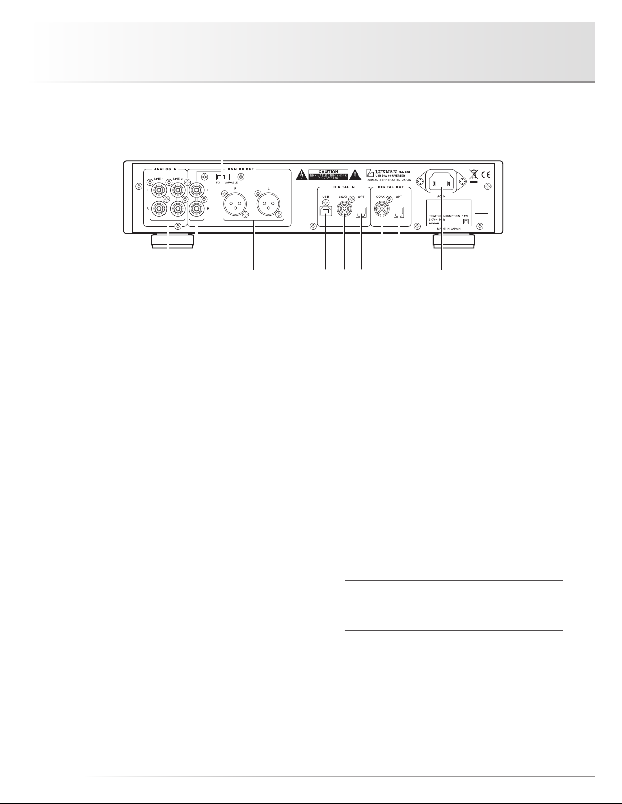
12. Analog balance output terminals (XLR)
These are XLR output terminals used for the balanced play-
back output signals from this unit.
These terminals does not output the playback signals from
a device connected to the analog input terminals (LINE-1/
LINE-2) of this unit. Besides, the level of the playback output
signals is always fixed regardless of the state of the line out-
put level fix/variable selection switch (FIX/VARIABLE).
The following are the polarities of output terminals of this
unit.
1. GROUND
2. COLD (–)
3. HOT (+)
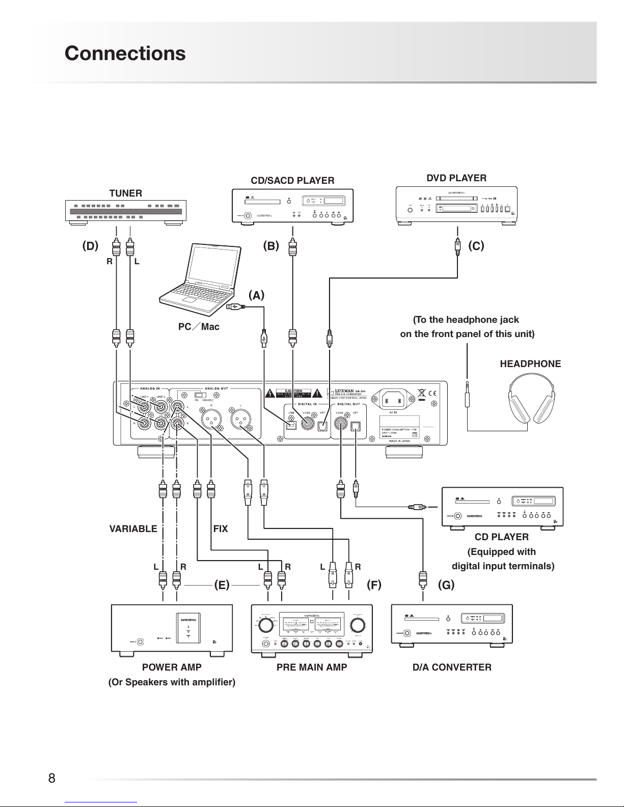
13. Digital input terminal (USB)
This is a USB 1.1 (B-type) input terminal used for the digital
input signal from such device as a PC/Mac using a USB
cable.
The terminal is applicable to the following data.
Sampling frequency: 32 kHz, 44.1 kHz, 48 kHz,
88.2 kHz, 96kHz, 176.4 kHz,
192 kHz
Number of quantization bits: 16 bit, 24 bit
However, a digital signal of 88.2 kHz, 176.4 kHz, or 192
kHz is input, the sampling frequency is internally converted
into 96 kHz.
14. Digital input terminal (COAX)
This is an RCA input terminal used for the digital input signal
from such device as a CD player equipped with digital out-
put terminals using a coaxial digital cable.
The terminal is applicable to the following data.
Sampling frequency: 32 kHz, 44.1 kHz, 48 kHz,
88.2 kHz, 96kHz, 176.4 kHz,
192 kHz
Number of quantization bits: 16 bit, 20 bit, 24 bit
15. Digital input terminal (OPT)
This is a TOS-LINK input terminal used for the digital input
signal from such device as a CD player equipped with digital
output terminals using an optical digital cable.
The terminal is applicable to the following data.
Sampling frequency: 32 kHz, 44.1 kHz, 48 kHz,
96 kHz, 176.4 kHz, 192 kHz
Number of quantization bits: 16 bit, 20 bit, 24 bit
16. Digital output terminal (COAX)
This is an RCA output terminal used to output the digital sig-
nal that has been input from the digital input terminal (OPT/
COAX/USB).
The digital input signal selected by rotating the input selec-
tor is output. The sampling frequency and the number of
quantization bits of the digital output signal are the same as
those of the input signal.
The playback signals from analog input terminals (LINE-1/
LINE-2) are not output from this terminal.
17. Digital output terminal (OPT)
This is a TOS-LINK output terminal used to output the digi-
tal signal that has been input from the digital input terminal
(OPT/COAX/USB).
The digital input signal selected by rotating the input selec-
tor is output. The sampling frequency and the number of
quantization bits of the digital output signal are the same
as those of the input signal, but since the channel status
indicating the digital format is reset only when the signal is
output from this terminal, the sampling frequency may be
displayed as 44.1 kHz on the D/A converter connected to
this unit.
The playback signals from analog input terminals (LINE-1/
LINE-2) are not output from this terminal.
Relational table of the input and output of DA-200
Output
Input
Headphone
output
Line output
Digital output
RCA XLR
OPT/COAX
Digital
input Variable Variable/
Fixed Fixed Available
Analog
input Variable Variable/
Fixed
Not
available
Not
available
18. AC inlet (AC IN)
Connects the accessory power cable. The power shall be
supplied from a household wall outlet.

8
Connections
HEADPHONE
PRE MAIN AMP
VARIABLE FIX
D/A CONVERTER
(To the headphone jack
on the front panel of this unit)
POWER AMP
(Or Speakers with amplifier)
TUNER
CD PLAYER
(Equipped with
digital input terminals)
LR
RL RL RL
CD/SACD PLAYER
PC/Mac
DVD PLAYER
(D) (B) (C)
(A)
(E) (F) (G)

USB D/A CONVERTER DA-200
9
How to connect power supply
Use the accessory power cable and insert the AC plug in an
outlet on the wall in the room where the unit will be installed.
How to connect input devices
1. Digital connection from a PC/Mac
(Refer to "A" in the connection
diagram.)
Connect between the USB 1.1 (A-type) input terminal of the
PC/Mac and the USB 1.1 (B-type) input terminal of this unit
with a USB cable.
The PC/Mac will automatically recognize this unit, and the
unit will be ready to operate.
2. Digital connection from such device as
a CD player
(Refer to "B" and "C" in the connection
diagram.)
Connect between the (coaxial or optical) digital output ter-
minal of a CD player, an SACD player, a DVD player, and
other such devices and the digital input terminal (COAX/
OPT) of this unit with a coaxial digital cable and an optical
digital cable.
This terminal has a shutter. Direct the cable connector
correctly when inserting the cable into the terminal. If the
cable connector is inserted forcibly with the wrong direction,
the terminal may be deformed, and the shutter may not be
able to close even after cable disconnection.
The optical terminals are directed as illus-
trated.
3. Analog connection from a CD player
(Refer to "D" in the connection
diagram.)
Connect between the analog output terminals of a CD play-
er, an SACD player, a tuner, a DVD player, a TV, and other
such devices and the analog input terminals (LINE-1/LINE-
2) of this unit with 2 (R and L) RCA pin-plug cables.
How to connect output devices
1. Unbalanced connection with such
device as a pre-main amplifier
(Refer to "E" in the connection
diagram.)
Connect between the analog unbalance output terminals
(RCA) of this unit and the unbalance input terminals of such
device as a pre-main amplifier with 2 (R and L) RCA pin-plug
cables.
At this connection, the sound volume of the output signal
change in accordance with the state of the line output level
fix/variable selection switch (FIX/VARIABLE).
FIX / VARIABLE
selection switch
FIX LINE-OUT
indicator
Sound
volume of the
output signal
Such device as
an amplifier to
be connected
FIX on Always fixed Pre-main
amplifier
VARIABLE off
Interlocked
with the
volume
control
Power-
amplifier /
Speakers
with amplifier
2. Balanced connection with such device
as a pre-main amplifier
(Refer to "F" in the connection
diagram.)
Connect between the analog balance output terminals (XLR)
of this unit and the balance input terminals of such device as
a pre-main amplifier with 2 (R and L) XLR balanced cables.
The line output level fix/variable selection switch is activated
only for the analog unbalance output. The sound volume of
the analog balance output is always fixed regardless of the
state of the selection switch.
3. Digital output to such device as another
D/A converter
(Refer to "G" in the connection
diagram.)
Connect between digital output terminal (COAX/OPT) of this
unit and such devices as a D/A converter and a CD player
equipped with digital input terminals with a coaxial digital
cable and an optical digital cable.
Upper side
Lower side

10
This unit is a D/A converter. Any operations for sound repro-
duction are performed with such input device as a PC/Mac or
CD player connected to the input terminals.
Before operation
1. Ensure that the connections are correctly performed.
(Normal playback cannot be achieved with wrong
connections of R and L.)
2. After ensuring that the volume control has been rotated
counterclockwise to the end and the sound volume is at
the minimum level, press the operation switch to turn on
the power of this unit.
Sound reproduction of a device connected
to a digital input terminal (Analog output)
1. Select an input device to be reproduced with the input
selector. (OPT/COAX/USB)
2. When the input devices starts reproduction, the digital
signal unlock indicator (UNLOCK) turns off, and the
sampling frequency of the playback signal is displayed on
the LED.
If the digital signal is not normally input to the unit, the digital
signal unlock indicator (UNLOCK) lights up, and signal is not
output.
3. If the line output level fix/variable selection switch (FIX/
VARIABLE) is set to FIX and if such device as a pre-main
amplifier is connected to the analog unbalance output
terminals (RCA) or the analog balance output terminals
(XLR), adjust the sound volume with the volume control of
the output device.
If the line output level fix/variable selection switch (FIX/
VARIABLE) is set to VARIABLE and if such device as a
power-amplifier or speakers with amplifier is connected to
the analog unbalance output terminals (RCA), adjust the
sound volume with the volume control of this unit.
Sound reproduction of a device connected
to an analog input terminal (Analog output)
1. Select an input device to be reproduced with the input
selector. (LINE-1/LINE-2)
2. If the line output level fix/variable selection switch (FIX/
VARIABLE) is set to FIX and if such device as a pre-main
amplifier is connected to the analog unbalance output
terminals (RCA) or the analog balance output terminals
(XLR), adjust the sound volume with the volume control of
the output device.
If the line output level fix/variable selection switch (FIX/
VARIABLE) is set to VARIABLE and if such device as a
power-amplifier or speakers with amplifier is connected to
the analog unbalance output terminals (RCA), adjust the
sound volume with the volume control of this unit.
FIX / VARIABLE
selection switch
FIX LINE-OUT
indicator
Sound
volume of the
output signal
Such device as
an amplifier to
be connected
FIX on Always fixed Pre-main
amplifier
VARIABLE off
Interlocked
with the
volume
control
Power-
amplifier /
Speakers
with amplifier
How to use the digital output
The playback signal that is input from a digital device to this
unit can be output from a digital output terminal to such de-
vices as another D/A converter and a CD player equipped
with digital input terminals.
A CD player equipped with no USB input terminals can re-
ceive digital signal that is input from the USB input terminal of
this unit by connecting between a digital input terminal (OPT/
COAX) of the player and a digital output terminal (OPT/COAX)
of the unit.
1. Select an input device to be reproduced with the input
selector. (OPT/COAX/USB)
2. Adjust the sound volume with the volume control of the
connected system device.
The digital output terminal does not output the playback
signals from a device connected to the analog input terminals
(LINE-1/LINE-2) of this unit.
Operations

USB D/A CONVERTER DA-200
11
How to use the headphone output
Insert the standard plug of a headphone into the headphone
jack (PHONES) on the front panel of this unit while the volume
control is rotated counterclockwise to the end. Start the re-
production of the input device, and rotate the volume control
slowly clockwise to your favorite sound volume.
When the power is toggled between on and off, the input
selector is changed over, or the headphone plug is connected
or disconnected, rotate the volume control counterclockwise
to the end to set the minimum sound volume.
If the headphone is used for a long time at a high sound
volume, that may cause hearing loss.
Applied use of the analog output terminals
If the line output level fix/variable selection switch (FIX/VARI-
ABLE) is set to VARIABLE and the analog unbalance output
terminals (RCA) of this unit and the main in terminals (MAIN
IN) of such device as a pre-main amplifier (such as Luxman L-
505u) equipped with the separate function , the pre-amplifier
section can be upgraded to a newly-designed pre-amplifier
circuit.

12
Block Diagram

USB D/A CONVERTER DA-200
13
Specifications
Format 2-channel, USB D/A converter
Ambient operating
temperature
+5 °C to +35 °C
Line input Input sensitivity/input
impedance
290mV / 24kΩ
Audio output
characteristics
Output voltage /
output impedance
UNBALANCE terminal (RCA terminal) Fixed output 2.5 Vrms/400Ω
UNBALANCE terminal (LINE terminal) Variable output 1.0
Vrms/400Ω
BALANCE terminal (XLR terminal) 2.5 Vrms/600Ω
PHONE terminal (Standard plug) 130mW + 130mW(600Ω)
80mW + 80mW (32Ω), 40mW + 40mW (16Ω)
Maximum output UNBALANCE terminal (RCA terminal) Variable output 10 Vrms
Frequency response DIGITAL IN 4 Hz to 20 kHz (+0,–0.4 dB)
DIGITAL IN 2 Hz to 60 kHz (+0,–3.0 dB)
ANALOG IN 10 Hz to 20 kHz (+0,–0.1 dB)
ANALOG IN 3 Hz to 130 kHz (+0,–3.0 dB)
Total harmonic
distortion
DIGITAL IN 0.0009 % / Unbalanced
DIGITAL IN 0.0006 % / Balanced
ANALOG IN 0.003 % / 1kHz (flat)
S/N ratio DIGITAL IN 119 dB
ANALOG IN 103 dB
Dynamic rang DIGITAL IN 120 dB
Channel separation DIGITAL IN 119 dB
Digital input
Coaxial digital input 0.2 to 2.5 Vp-p
Optical digital input –14.5 to –24 dBm
USB input
(Applicable OS)
Microsoft Windows XP or later, Mac OS X or later
Sampling frequency OPT/COAX input : 32 kHz, 44.1 kHz, 48 kHz, 88.2 kHz,
96 kHz, 176.4 kHz, 192 kHz
(16 bit,20 bit,24 bit)
USB input : 32 kHz, 44.1 kHz, 48 kHz, 96 kHz
(16 bit,24 bit)
Digital output Coaxial digital output RCA terminal 0.5 Vp-p/75Ω
Optical digital input Optical digital terminal –15 〜–21 dBm
Accessories • Power cable • Owner's Manual
• Safety cautions
Power supply voltage AC230 V,50 Hz
Power consumption 11 W
Weight (Main unit) 5.1 kg
Dimensions 364 (W) ×81 (H) ×257 (Knobs (14 mm) and terminals (8mm)
included) (D) mm
* Specifications and appearance are subject to change without notice.

14
Before Asking for Repair Services
While the unit is used, an unusual phenomenon may be confused as a malfunction for a certain reason. Prior to asking us for repair
services, please check the table below and read the instruction manual for the subsidiary devices. If the cause of the malfunction
cannot be identified, please contact your dealer. Besides, such personal computer as a PC/Mac connected to the unit and the
software that operates on the PC/Mac (operations and settings included) are not supported.
Problem Cause/Solution Ref. page
No power is supplied even
though the operation switch is
pressed.
· Connect the power cable to the AC inlet (AC IN) and the AC outlet
firmly.
9
No sound is generated. / Sound
volume is too low.
· Connect the input devices, amplifier, speakers, and headphone cor-
rectly.
8〜9
· Set the input selector to the source to be reproduced. 10
· When you are listening to the sound of a headphone or the variable
line output (unbalanced), adjust the sound volume with the volume
control of the unit.
10〜11
· When you are listening to the sound of a fixed line output (unbal-
anced) or the balance output, adjust the sound volume with the vol-
ume control of the connected amplifier.
10〜11
No sound is generated. / Sound
volume is too low. (Digital input)
· Connect digital cables correctly. 8〜9
· If the USB is selected as an input source, select this unit (DA-200) as
the output destination by configuring the sound setting of a PC/Mac.
Refer to the instruc-
tion manual of the
PC/Mac or the
software in use.
· If the unit (DA-200) cannot be selected even when trying the solution
above, reconnect the USB cable.
· If the USB is selected as an input source, adjust the sound volume by
configuring the sound setting of a PC/Mac.
· If the USB is selected as an input source, adjust the sound volume on
a player software of a PC/Mac.
· Ensure that the sampling frequency and the number of quantization
bits of the reproduced digital signal are applicable to this unit.
7
· Ensure that the digital signal unlock indicator (UNLOCK) does not light
up. (When the digital signal from the digital device is not synchronized
with this unit, the source may not be reproduced.)
5
Humming sound (boon or zzz
noise) is generated.
· Insert the RCA pin-plugs of the line cables firmly. 8
· Induction noise may be picked up from the power transformer of
another device. Install this unit distantly from the other device.
· When you are listening to the sound of a headphone, arrange the
headphone cable and the power cable so that they are not laid too
close.
This unit may not work normally when the unit is subject to external influence such as static electricity. In such a case, the
unit can work normally by unplugging the power cable once and plugging it again. If the cause of malfunction cannot be
identified, please contact your dealer.

USB D/A CONVERTER DA-200
15
MEMO

16
MEMO


AG00987C81A
Printed in Japan
LUXMAN CORPORATION, JAPAN
Table of contents
Other Luxman Media Converter manuals
Popular Media Converter manuals by other brands

Transition Networks
Transition Networks ARCNET AR-CF-01(SC) user guide

ICP DAS USA
ICP DAS USA I-7530 Quick start user guide

Travel Smart
Travel Smart TS703CR user manual

TR-Electronic
TR-Electronic LMR-70-180 ANA-I+JUSTAGE manual

DirectOut Technologies
DirectOut Technologies split.converter user manual

Linetek
Linetek SPL-DVI-0104E user manual