exemys EGW1-MB-HT User manual

Rev. 4

Rev. 4
INDEX
INDEX
INDEXINDEX
INDEX
_________________________________________________________________________ 2
1
11
1
INTRODUCTION
INTRODUCTIONINTRODUCTION
INTRODUCTION
______________________________________________________________ 3
1.1 Purpose of the manual __________________________________________________________ 3
1.2
1.21.2
1.2 Product
Product Product
Product Overview
OverviewOverview
Overview _______________________________________________________________ 3
1.3
1.31.3
1.3 Ordering Codes
Ordering CodesOrdering Codes
Ordering Codes _________________________________________________________________ 3
1.4
1.41.4
1.4 Technic l Specific tions
Technic l Specific tionsTechnic l Specific tions
Technic l Specific tions ___________________________________________________________ 4
2
22
2
INSTALLA
INSTALLAINSTALLA
INSTALLATION
TIONTION
TION
_______________________________________________________________ 5
2.1 Connecting the power supply ____________________________________________________ 5
2.2
2.22.2
2.2 Seri l Port Wirings
Seri l Port WiringsSeri l Port Wirings
Seri l Port Wirings _______________________________________________________________ 5
2.3.
2.3.2.3.
2.3. HART Port
HART PortHART Port
HART Ports
ss
s ____________________________________________________________________ 6
2.4.
2.4.2.4.
2.4. LEDS Indic tors
LEDS Indic torsLEDS Indic tors
LEDS Indic tors _________________________________________________________________ 8
3
33
3
CONFIGURATION
CONFIGURATIONCONFIGURATION
CONFIGURATION
____________________________________________________________ 10
3.1 Networ Configuration _________________________________________________________ 10
3.2 Configuration web page ________________________________________________________ 11
3.3 Modbus Configuration _________________________________________________________ 12
3.4 HART Configuration ___________________________________________________________ 13
3.5.
3.5.3.5.
3.5. Administr tor Settings
Administr tor SettingsAdministr tor Settings
Administr tor Settings ___________________________________________________________ 13
3.6.
3.6.3.6.
3.6. WEB Monitoring
WEB MonitoringWEB Monitoring
WEB Monitoring _______________________________________________________________ 15
4
44
4
MODBUS REGISTERS
MODBUS REGISTERSMODBUS REGISTERS
MODBUS REGISTERS
___________________________________________________________ 16
4.1
4.14.1
4.1 Modbus prim ry m p (flo t 32)
Modbus prim ry m p (flo t 32)Modbus prim ry m p (flo t 32)
Modbus prim ry m p (flo t 32) ____________________________________________________ 16
4.2 Modbus ltern tive m p (32 bits integer)
Modbus ltern tive m p (32 bits integer)Modbus ltern tive m p (32 bits integer)
Modbus ltern tive m p (32 bits integer)_____________________________________________ 17
5
55
5
MONITORING, MANUAL SENDING, HART OVER TCP
MONITORING, MANUAL SENDING, HART OVER TCPMONITORING, MANUAL SENDING, HART OVER TCP
MONITORING, MANUAL SENDING, HART OVER TCP
_________________________________ 18
7.1 Data Monitoring ______________________________________________________________ 18
7.2 Manual sending of HART commands ______________________________________________ 18
7.3 Transparent Mode (HART over TCP) ______________________________________________ 19
A. COMMAND CONSOLE
A. COMMAND CONSOLEA. COMMAND CONSOLE
A. COMMAND CONSOLE
__________________________________________________________ 20
B. IP ADDRESS USIN
B. IP ADDRESS USINB. IP ADDRESS USIN
B. IP ADDRESS USING ARP PROTOCOL
G ARP PROTOCOLG ARP PROTOCOL
G ARP PROTOCOL
________________________________________________ 22
C. FACTORY SETTINGS
C. FACTORY SETTINGSC. FACTORY SETTINGS
C. FACTORY SETTINGS
____________________________________________________________ 24
D. DIN RAIL MOUNTING
D. DIN RAIL MOUNTINGD. DIN RAIL MOUNTING
D. DIN RAIL MOUNTING
___________________________________________________________ 25
E. EGW1
E. EGW1E. EGW1
E. EGW1-
--
-MB
MBMB
MB-
--
-HT with PACTw re© in tr nsp rent mode
HT with PACTw re© in tr nsp rent modeHT with PACTw re© in tr nsp rent mode
HT with PACTw re© in tr nsp rent mode
___________________________________ 26

Rev. 4
1
11
1INT
INTINT
INTRODU
RODURODU
RODUCTION
CTIONCTION
CTION
1.1
1.11.1
1.1 Purpose of the manual
Purpose of the manualPurpose of the manual
Purpose of the manual
This m nu l provides the instructions for e sy nd quick inst lling nd oper ting of the EGW1
EGW1EGW1
EGW1-
--
-MB
MBMB
MB-
--
-HT
HTHT
HT.
The m nu l st rts with gener l description of the product, following the instructions for the correct
h rdw re inst ll tion. Configur tion nd oper tion of the device is det iled below.
1.2
1.21.2
1.2 Product Overview
Product OverviewProduct Overview
Product Overview
EGW1-MB-HT module is device used to connect ny instrument with HART communic tion to one or
more Modbus M sters, Modbus TCP or Modbus Seri l (RTU / ASCII).
Device h s 3 independent Modbus ports. One Ethernet for Modbus TCP, one RS232 nd the other RS485
opto-isol ted for Modbus RTU / ASCII
1.3
1.31.3
1.3 Ordering Codes
Ordering CodesOrdering Codes
Ordering Codes
Ordering Code Description
Ordering Code DescriptionOrdering Code Description
Ordering Code Description
EGW1-110-3-IA3-MB-HT
(3) HART ports / (1) RS232 port / (1) RS485 opto
-
isol ted port
(1) Ethernet port 10/100 Mbps

Rev. 4
1.4
1.41.4
1.4 Technic l Specific tions
Technic l Specific tionsTechnic l Specific tions
Technic l Specific tions
Technic l Specific tion
Technic l Specific tionTechnic l Specific tion
Technic l Specific tion
Network Protocols
Network ProtocolsNetwork Protocols
Network Protocols
Modbus TCP, TCP / IP, DNS, HTTP, DHCP, ICMP, ARP, SNMP
Network
NetworkNetwork
Network
Port
PortPort
Port
Ethernet 10 / 100 Mbps, RJ45 Connector
Seri l Protocol
Seri l ProtocolSeri l Protocol
Seri l Protocol
Modbus RTU, Modbus ASCII
Seri l Port
Seri l PortSeri l Port
Seri l Port
(1) RS232 port / (1) RS485 opto-isol ted port
Plugg ble Termin l Block connection
Supported devices
Supported devicesSupported devices
Supported devices
Any HART Device
Device M n gement
Device M n gementDevice M n gement
Device M n gement
HTTP Server, p ssword protected
RS-232 Seri l Console
Firmw re Upd te
Firmw re Upd teFirmw re Upd te
Firmw re Upd te
From Web P ge
Led Indic tors
Led Indic torsLed Indic tors
Led Indic tors
St tus, D t / Link
Me surements
Me surementsMe surements
Me surements
100mm x 22,5mm x 112mm (Height x Width x Length)
Power Supply
Power SupplyPower Supply
Power Supply
10 to 30 VDC
Consumption
ConsumptionConsumption
Consumption
12VDC 80mA/ 24VDC50mA
Temper tures
Temper turesTemper tures
Temper tures
Oper tion Temper ture: -15°C to 65 °C
Stor ge Temper ture: -40°C to 75 °C
W rr nty
W rr ntyW rr nty
W rr nty
1 Ye r
Technic l Support Included

Rev. 4
2
22
2I
II
INSTALLATION
NSTALLATIONNSTALLATION
NSTALLATION
2.1
2.12.1
2.1 Connecting the power supply
Connecting the power supplyConnecting the power supply
Connecting the power supply
EGW1-MB-HT llows power supply from +10 to 30 VDC. Positive power supply must be connected to
termin l N° 1 nd neg tive power supply to termin l No. 2 s shown in the following figure:
2.2
2.22.2
2.2 Seri l Port Wirings
Seri l Port WiringsSeri l Port Wirings
Seri l Port Wirings
EGW1-MB-HT h s two seri l ports; one of them is RS232 (Port A), used s Modbus sl ve nd s
configur tion port through the seri l (Appendix A), nd other one RS485 (Port B) used s Modbus Sl ve.
2.2.1.
2.2.1.2.2.1.
2.2.1. RS232 port wirin
RS232 port wirinRS232 port wirin
RS232 port wiring (Port A)
g (Port A)g (Port A)
g (Port A)
To connect the device RS232 seri l port to PC seri l port or ny other seri l device to set nd monitor, it
must be connected s c n be shown in the following figure. You should consider EGW1-MB-HT is DTE
device, th t me ns it must cross wire with those of the PC.
2.2.2.
2.2.2.2.2.2.
2.2.2. RS485 port wiring (Port B)
RS485 port wiring (Port B)RS485 port wiring (Port B)
RS485 port wiring (Port B)
To connect the device RS485 opto-isol ted seri l port to ny seri l device, it must be connected s c n be
shown in the following figure. The oper tion of this port is independent of the RS232. An isol ted GND
termin l is v il ble in the termin l if n RS485 c ble with mesh wire is used.

Rev. 4
2.3.
2.3.2.3.
2.3. HART
HARTHART
HART
Ports
PortsPorts
Ports
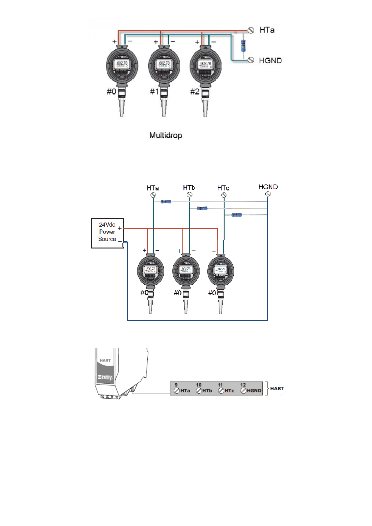
EGW1-MB-HT h s three HART ports:
HT , HTb
nd
HTc
. All the three ports sh re the HGND termin l to
close the loop.
One or more HART instruments c n be connected to e ch port. To connect two or more instruments, they
must be configured in MULTIDROP mode nd denote different HART ddress to e ch one.
E ch loop must be closed with n extern l resist nce of 250 ohms. The resist nce must dissip te power
equiv lent to the squ re of the m ximum current of e ch instrument multiplied by the v lue of the
resist nce.
= ( ) 250 ℎ
Ex mple, for 3 instruments gener ting up to 4 mA in Multidrop mode:
= (3 4) 250 ℎ = 36
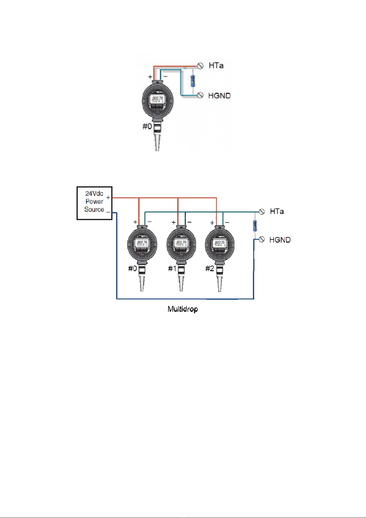
Connection di gr m for3 tr nsmitters in Multidrop mode to the
HT
port
Three 250 ohm 250 mW resistors of re provided to the user together with the device
2.2.1 One p ssive
One p ssiveOne p ssive
One p ssive tr nsmitter to HT port wiring di gr m
Rev. 4
2.2.2 One ctive
One ctiveOne ctive
One ctive tr nsmitter to HT port wiring di gr m
2.2.3 Three p ssive
Three p ssiveThree p ssive
Three p ssive tr nsmitters to HT port in Multidrop
MultidropMultidrop
Multidrop mode wiring di gr m
2.2.4 Three ctive
Three ctiveThree ctive
Three ctive tr nsmitters to HT port in Multidrop
MultidropMultidrop
Multidrop mode wiring di gr m
Rev. 4
2.2.5 Three p ssive
Three p ssiveThree p ssive
Three p ssive tr nsmitters to in NO Multidrop
NO MultidropNO Multidrop
NO Multidrop mode to ports HT ,
HTb nd HTc
wiring di gr m
2.4.
2.4.2.4.
2.4. LEDS
LEDSLEDS
LEDS
Indic tors
Indic torsIndic tors
Indic tors
EGW1-MB-HT h s three LEDs, two of them on the Ethernet connector, the yellow one shows the
connection to the network, while the green one indic tes the st tus of the Modbus TCP connection.

Rev. 4
The Power LED indic tes device is on.
Green
GreenGreen
Green
Yellow
YellowYellow
Yellow
Description
DescriptionDescription
Description
-
Continuously on Looking for DHCP server.
-
1/2 second on nd 1/2 second off. W iting for configur tion ping nd / or w iting seri l console.
- 90% of second off nd the
rem ining time on.
Device h s n IP ddress nd connection be rer link. This is the
norm l oper ting st te
- 10% of second off nd the
rem ining time on.
It h s no IP ddress nd c nnot find the DHCP server. It will se rch
the DHCP server for in 60 seconds.
- Fl shing very f st L ck of Ethernet link
(C ble disconnected).
On - Modbus TCP connection set.
Fl shing off - Tr nsmission or reception of d t .
Fl shing ltern tively with
Yellow LED
Fl shing ltern tely with the Green
LED Critic l F ilure. Cont ct technic l support

Rev. 4
3
33
3CONFIGURATION
CONFIGURATIONCONFIGURATION
CONFIGURATION
3.1
3.13.1
3.1 Network Configuration
Network ConfigurationNetwork Configuration
Network Configuration
EGW1-MB-HT configur tion is done through configur tion web p ge connecting the device to the
Ethernet network on which it is going to work.
To ccess to the configur tion web p ge, you must connect EGW1-MB-HT to ethernet network nd inst ll
Exemys Device Loc tor
softw re.
Downlo d the
Exemys Device Loc tor
:
http://www.exemys.com/bet /softw re/edl_setup.exe
Once the device is connected, this will se rch for DHCP server to obt in n IP ddress utom tic lly. We
will se rch for it using the
Exemys Device Loc tor
softw re, which llows us se rching, identifying nd
configuring the b sic network p r meters. The rest of the configur tion is done from the configur tion
web p ge of the device.
In c se you do not h ve DHCP server, the
Exemys Device Loc tor
will find the device with IP
ddress 0.0.0.0, s shown in the figure below.
If you do not h ve DHCP server, give it n IP ddress using the
Exemys Device Loc tor
button or
using the methods expl ined in Appendix B
Appendix BAppendix B
Appendix B.
The
Exemys Device Loc tor
buttons re:
Query Network
Query NetworkQuery Network
Query Network: Se rches for ll connected EXEMYS devices on the s me network.
Properties ...
Properties ...Properties ...
Properties ...: Configuring Network P r meters (IP Address, Network M sk, G tew y)
Configure...
Configure...Configure...
Configure...: Direct ccess to the configur tion web p ge.

Rev. 4
3.2
3.23.2
3.2 Configuration web page
Configuration web pageConfiguration web page
Configuration web page
Once the EGW1-MB-HT h s v lid IP ddress, you c n ccess the web p ge to configure the other
p r meters (If your web browser is configured to se rch for proxy server, dis ble this option)
Type the EGW1-MB-HT IP ddress in the ddress field of your browser or from the
Exemys Device Loc tor
,
press the Configure button.
If you configured p ssword, the computer will sk for it when entering the web p ge.
In this c se, you must enter " dmin
dmindmin
dmin" s the user nd then the p ssword th t w s set.
If you w nt to ch nge it, you c n do it from the Administr tor
Administr torAdministr tor
Administr tor menu

Rev. 4
3.3
3.33.3
3.3 Modbus
ModbusModbus
Modbus
Configuration
ConfigurationConfiguration
Configuration
EGW1-MB-HT h s n intern l Modbus sl ve cont ining the v lues of ll HART devices configured.
This sl ve c n be ccessed by multiple me ns of communic tion: Ethernet (Modbus TCP), RS232 nd
RS485 (Modbus RTU or ASCII)
Modbus TCP
Modbus TCPModbus TCP
Modbus TCP
The only possible configur tion is to define the connection port of the Modbus TCP sl ve. The TCP sl ve
responds to ll IDs nd responds to exceptions
Seri l Ports RS232/RS485
Adv nce Configur tion
Adv nce Configur tionAdv nce Configur tion
Adv nce Configur tion
It is possible to determine some specific p r meters of the Modbus m p so th t it d pts to our needs.
Among the different configur tions we h ve, the order of the flo ting-point v lues, if they re pl ced in
one direction or nother.
Rev. 4
Another ch r cteristic is to define the beh vior in c se of f ilure, if the connected device h s
m lfunction, we c n determine in the v lues of the Modbus m p beh vior th t is defined in 3 options:
Keep the l st v lue re d, show N N or predefined v lue th t is useful.
3.4
3.43.4
3.4 ART
ARTART
ART
Configuration
ConfigurationConfiguration
Configuration
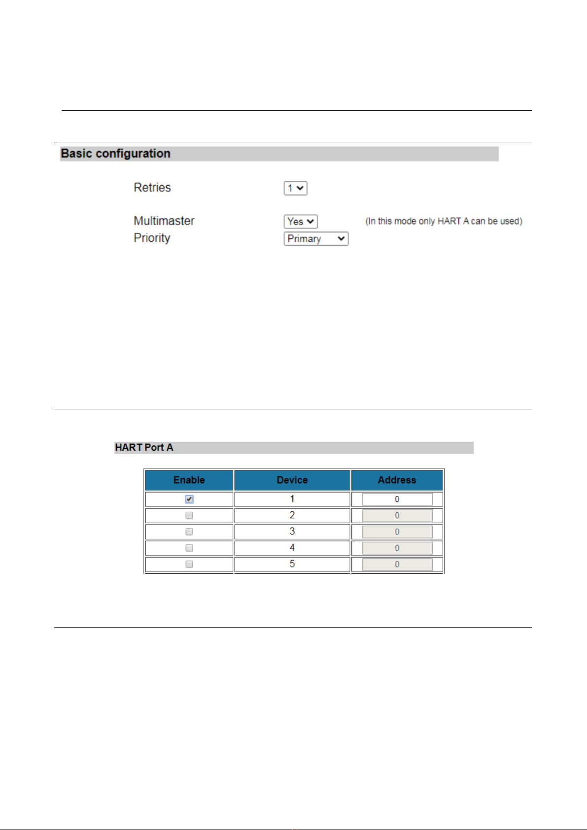
B sic Configur tion
Here you c n configure how m ny tries the HART m ster will do before indic ting communic tion error.
Since firmw re 1.3 the EGW1-MB con work long nother HART m ster (Multim ster mode).
Once you en ble this option you must select we ther the EGW1 will be the prim ry or the second ry
m ster.
In Multim ster mode only HART A port will be v il ble.
In Multim ster mode only HART A port will be v il ble.In Multim ster mode only HART A port will be v il ble.
In Multim ster mode only HART A port will be v il ble.
T ble of device
It is the t ble th t tells us which devices we h ve connected nd which short ddress they h ve.
E ch port h s its t ble. It is import nt not to repe t ddresses in the s me port.
3.5.
3.5.3.5.
3.5. Ad
AdAd
Administr
ministrministr
ministr t
tt
tor
oror
or
Settings
SettingsSettings
Settings
In the Administr tor
Administr torAdministr tor
Administr tor menu you c n find device dministr tion tools.

Rev. 4
P ssword
The web p ge nd the configur tion by
Exemys Device Loc tor
c n be protected with p ssword. This
p ssword c n lso be set from the
Exemys Console
(see Appendix A
Appendix AAppendix A
Appendix A).
It only dmits lph numeric ch r cters. The user to enter when sked is "
dmin
dmindmin
dmin
".
To delete the p ssword, only n empty p ssword must be s ved.
Rest rt
If necess ry, the device c n be rest rted. In this w y ll your connections will be closed nd ll your t sks
will st rt g in s if the device h d just been energized.
Restore f ctory settings
The user c n return the device to its origin l f ctory settings. This option c n be executed from the web
p ge or from the Exemys Console (see Appendix A
Appendix AAppendix A
Appendix A).
Firmw re Upd te
The device's firmw re c n be upd ted in c se new versions with improvements rise.
By pressing the Upd te
Upd teUpd te
Upd te button, the web p ge will request you select the upd te file.
Then press the Downlo d
Downlo dDownlo d
Downlo d button nd through inform tive mess ges you c n follow the upd te process.
The device will rest rt nd be re dy to oper te g in fter the downlo d.

Rev. 4
3.6.
3.6.3.6.
3.6. WEB
WEBWEB
WEB
Monitoring
MonitoringMonitoring
Monitoring
It llows to show the st tus of the HART v ri bles; this is possible by blocks of 4 sensors ccording to
port nd sensors.
Colors indic te the st tus, gr y in ctive, red is ctive but in f ilure (communic tion problems) nd white
indic tes th t the sensor is responding correctly.

Rev. 4
4
44
4MODBUS REGISTERS
4.1
4.14.1
4.1 Modbus prim ry m p (flo t 32)
Modbus prim ry m p (flo t 32)Modbus prim ry m p (flo t 32)
Modbus prim ry m p (flo t 32)
The v lues re d from HART devices re v il ble in HOLDING REGISTER nd INPUT REGISTER re .
For e ch HART device, 20 registers re reserved.
Registers of the HART PORT A first device
The registers of HART PORT A second device c n be found from the register 40021/30021
The registers of HART PORT B firstdevice c n be found from the register 40321/30321
The registers of HART PORT C firstdevice c n be found from the register 40641/30641
St tus Registers of e ch HART device in e ch port
HART
HARTHART
HART
Address
AddressAddress
Address
HART A
HART AHART A
HART A
HART B
HART BHART B
HART B
HART C
HART CHART C
HART C
1 40001 40321 40641
2 40021 40341 40661
3 40041 40361 40681
4 40061 40381 40701
5 40081 40401 40721
6 40101 40421 40741
7 40121 40441 40761
8 40141 40461 40781
9 40161 40481 40801
10 40181 40501 40821
11 40201 40521 40841
12 40221 40541 40861
13 40241 40561 40881
14 40261 40581 40901
15 40281 40601 40921
16 40301 40621 40941
Holding
HoldingHolding
Holding
Register
RegisterRegister
Register
Input
InputInput
Input
Register
RegisterRegister
Register
V l
V lV l
V lue
ueue
ue
Form t
Form tForm t
Form t
40001 30001 Est do
0: f
il or dis bler dis bled
1: HART OK
40002 30002 reserved -
40003 – 40004 30003 – 30004 Current [mA] Flo t 32
40005 – 40006 30005 – 30006 1st v ri ble Flo t 32
40007 – 40008 30007 – 30008 2nd v ri ble Flo t 32
40009 – 40010 30009 – 30010 3rd v ri ble Flo t 32
40011 – 40012 30011 – 30012 4th v ri ble Flo t 32
40013 – 40020 30013 – 30020 reserved -

Rev. 4
V lue to dd to the St tus Register ddress of e ch device
Ex mple:
To re d the 2nd v ri ble of the device number 8 connected to the HART Port C
40781+7=40788
4.2 Modbus ltern tive m p
Modbus ltern tive m pModbus ltern tive m p
Modbus ltern tive m p
(32 bits
(32 bits(32 bits
(32 bits
integer
integerinteger
integer)
))
)
Since firmw re version 1.2 new Modbus m p is dded where HART v ri bles re presented in int32
form t inste d of flo t 32
The integer v lues is equ l to the flo ting point v lue times 100
The integer v lues is equ l to the flo ting point v lue times 100The integer v lues is equ l to the flo ting point v lue times 100
The integer v lues is equ l to the flo ting point v lue times 100.
..
.
To get the Modbus integer ddress you h ve to dd 1000 to the flo ting point v lue ddress.
To get the Modbus integer ddress you h ve to dd 1000 to the flo ting point v lue ddress.To get the Modbus integer ddress you h ve to dd 1000 to the flo ting point v lue ddress.
To get the Modbus integer ddress you h ve to dd 1000 to the flo ting point v lue ddress.
An ex mple below:
Add
AddAdd
Add
V l
V lV l
V l
ue
ueue
ue
Form t
Form tForm t
Form t
+0
St tus
*
0 / 1
+3
C
u
rrent [mA]
F
lo
t
32
+5
1st v ri ble
Flo
t
32
+7
2nd v ri ble
Flo
t
32
+9
3rd v ri ble
Flo
t 32
+11
4th v ri ble
Flo
t
32

Rev. 4
5
55
5MONITORING, MANUAL SENDING, HART OVER TCP
MONITORING, MANUAL SENDING, HART OVER TCPMONITORING, MANUAL SENDING, HART OVER TCP
MONITORING, MANUAL SENDING, HART OVER TCP
7.1
7.17.1
7.1 Data Monitoring
Data MonitoringData Monitoring
Data Monitoring
EGW1-MB-HT llows to monitor the communic tion between the device nd the HART tr nsmitters
connected to its ports.
For this you must set TCP connection to port 999
999999
999 with some TCP client termin l softw re (for ex mple
Putty or HyperTermin l)
Once the connection is est blished, you will see the d t sent by the device through its three ports (A>,
B>, C>) nd the responses of the tr nsmitters (<) expressed in hex decim l. In the event th t HART
tr nsmitter does not respond, the text "
Timeout
" will be displ yed.
A>
A>A>
A> FF FF FF FF FF FF FF 02 00 00 00 02
<
<<
<-
--
-Timeout
C>
C>C>
C> FF FF FF FF FF 82 62 E6 D7 18 49 03 00 83
<
<<
<-
--
-
FF FF FF FF FF 86 22 E6 D7 18 49 03 15 00 41 40 63 33 34 2D 00 00 00 00 20 41 95 33 30 29 C1 20 00 00 A5
7.2
7.27.2
7.2 M
MM
Manual
anual anual
anual sending of
sending of sending of
sending of ART
ARTART
ART
commands
commandscommands
commands
This function llows to send HART fr mes m nu lly. This llows to m ke djustments in the configur tion
of the HART tr nsmitters once they re lre dy inst lled in the field.
For this you must est blish TCP connection to port 998
998998
998 with some TCP client termin l softw re (for
ex mple Putty or HyperTermin l)
When connecting to port 998, the user must select the HART port to which it wishes to send the m nu l
comm nd by pressing the letters A, B or C.
Select HART port A, B or C
Then the user must write the fr me to be sent in hex decim l text nd press ENTER
hex decim l text nd press ENTERhex decim l text nd press ENTER
hex decim l text nd press ENTER (ASCII 13) upon
completion. It is not necess ry to write the 0xFF codes of the pre mble or dd the CRC t the end
bec use it is c lcul ted utom tic lly.
The fr me sent will be s ndwiched between regul r re d queries.
Ex mple 1: Send the comm nd 00 (re d unique identifier) to HART tr nsmitter with short ddress 00 on
the HART port C.
Select HART port A, B or C
Port C
02 00 00 00 ->
<- FF FF FF FF FF 06 00 00 0E 00 41 FE 62 E6 05 05 01 01 08 00 D7 18 49 BD
Ex mple 2: Send comm nd 15 (re d output inform tion) to HART tr nsmitter with long ddress 62E6-
D71849 on the HART port A.
Select HART port A, B or C
Port A

Rev. 4
82 62 E6 D7 18 49 0F 00 ->
<- FF FF FF FF FF 86 22 E6 D7 18 49 0F 13 00 41 01 00 2D3F 80 00 003F 00 00 0100
0000 00FB 62 AD
7.3
7.37.3
7.3 Transparent
Transparent Transparent
Transparent Mod
ModMod
Mode
ee
e
( ART
( ART ( ART
( ART over
overover
over
TCP)
TCP)TCP)
TCP)
This function llows the EGW1-MB-HT to be used s HART converter over TCP to HART. This llows the
configur tion softw re of e ch tr nsmitter to be used remotely, rriving t the loc tion through TCP
connection. Prob bly it is necess ry to use virtu l COM port softw re (such s Seri l IP) to get from the
softw re to EGW1-MB-HT.
•E ch device HART port h s n ssigned TCP port ssigned to the tr nsp rent mode. Port HART A:
10001
1000110001
10001, Port HART B: 10002
1000210002
10002, Port HART C: 10003
1000310003
10003
•The device will stop sending its own HART queries, while the connection to this port l sts
•The communic tion in tr nsp rent mode c nnot be monitored on port 999
•No ddition l byte type is dded to the fr me
Ple se refer to Appendix E to see how to do it using PACTw re.

Rev. 4
A.
A. A.
A. C
CC
COMMAND CONSOLE
OMMAND CONSOLEOMMAND CONSOLE
OMMAND CONSOLE
EGW1
EGW1EGW1
EGW1-
--
-MB
MBMB
MB-
--
-HT
HTHT
HT c n be set through comm nd console connecting the device to seri l port on the PC.
To ccess the comm nd console, you must connect the EGW1
EGW1EGW1
EGW1-
--
-MB
MBMB
MB-
--
-HT
HTHT
HT to RS232 port on PC nd you
must inst ll n Exemys seri l termin l progr m, c lled
Exemys Console.
Downlo d the
Exemys Console
:
http://www.exemys.com/console
Once the seri l termin l progr m is inst lled, connect the EGW1
EGW1EGW1
EGW1-
--
-MB
MBMB
MB-
--
-HT
HTHT
HT to RS232 port on the PC nd
execute the
Exemys Console
.
1. Click on Connection -> Seri l Port, it will open window with n me of ll COM Seri l port. Select
with double click the port where device is connected. Verify B ud r te in the seri l por is 9600.
2. Turn on the EGW1
EGW1EGW1
EGW1-
--
-MB
MBMB
MB-
--
-HT
HTHT
HT nd in the first 7 seconds type CFG nd press ENTER or press the CFG
button. EGW1
EGW1EGW1
EGW1-
--
-MB
MBMB
MB-
--
-HT
HTHT
HT will displ y welcome mess ge on the configur tion comm nd console.
Other manuals for EGW1-MB-HT
2
This manual suits for next models
1
Table of contents
Other exemys Media Converter manuals


