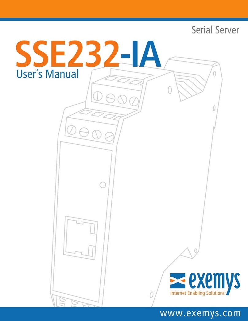
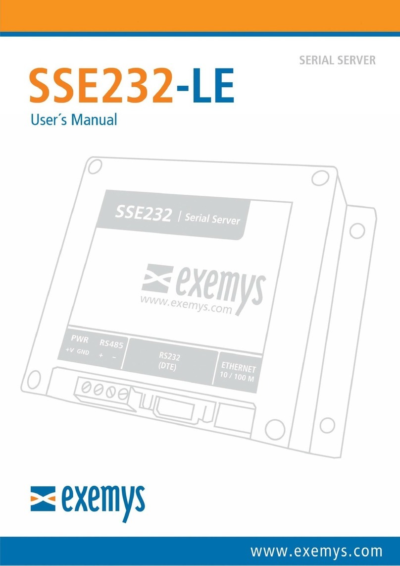
exemys SSE232-LE User manual

SSE232-LE – Serial Server- User’s Manual Exemys
www.exemys.com Rev.6 1

SSE232-LE – Serial Server- User’s Manual Exemys
www.exemys.com Rev.6 2
Exemys Products are in constant evolution to satisfy our customer needs.
For that reason, the specifications and capabilities are subject to change without prior notice.
Updated information can be found at www.exemys.com
Copyright Exemys, 2007. All Rights Reserved.

SSE232-LE – Serial Server- User’s Manual Exemys
www.exemys.com Rev.6 3
INDEX
INDEXINDEX
INDEX
1 INTRODUCTION .................................................................................................................. 5
1.1
1.11.1
1.1 Purpose of the manual
Purpose of the manualPurpose of the manual
Purpose of the manual .............................................................................................................. 5
1.2
1.21.2
1.2 Product Overview
Product OverviewProduct Overview
Product Overview ..................................................................................................................... 5
1.3
1.31.3
1.3 Ordering Codes
Ordering CodesOrdering Codes
Ordering Codes ........................................................................................................................ 6
1.4
1.41.4
1.4 Technical
Technical Technical
Technical Specifications
SpecificationsSpecifications
Specifications ............................................................................................................. 6
2 INSTALLATION .................................................................................................................... 7
2.1 Connecting the power supply ................................................................................................. 7
2.
2.2.
2.2
22
2 Serial Port Wirings
Serial Port WiringsSerial Port Wirings
Serial Port Wirings .................................................................................................................... 7
2.2.1 RS-232 serial port Wirings ........................................................................................................................... 7
2.2.2 RS-485 serial port wirings ........................................................................................................................... 8
2.3
2.32.3
2.3 Ethernet Connection
Ethernet ConnectionEthernet Connection
Ethernet Connection ................................................................................................................. 9
2.4
2.42.4
2.4 LEDs Indicators
LEDs IndicatorsLEDs Indicators
LEDs Indicators ........................................................................................................................ 9
3 CONFIGURATION .............................................................................................................. 10
3.1 Network configuration ......................................................................................................... 10
3.2
3.23.2
3.2 Configuration Web Page
Configuration Web PageConfiguration Web Page
Configuration Web Page .......................................................................................................... 11
3.3 Operation odes ................................................................................................................. 11
3.3.1 Server Mode ............................................................................................................................................. 12
3.3.2 Client Mode .............................................................................................................................................. 13
3.4
3.43.4
3.4 Common par
Common parCommon par
Common parameters
ametersameters
ameters .............................................................................................................. 14
3.4.1 Serial Port Config ration ........................................................................................................................... 14
3.4.2 Packaging .................................................................................................................................................. 15
3.4.3 Inactivity.................................................................................................................................................... 15
4 TYPICAL USES .................................................................................................................... 16
4.1 Connection with Serial Port Redirector ................................................................................. 16
4.2
4.24.2
4.2 TCP Point
TCP PointTCP Point
TCP Point-
--
-to
toto
to-
--
-Point Tunnel
Point TunnelPoint Tunnel
Point Tunnel ........................................................................................................ 16
4.3
4.34.3
4.3 UDP Point
UDP PointUDP Point
UDP Point-
--
-to
toto
to-
--
-Point Tunnel
Point TunnelPoint Tunnel
Point Tunnel ....................................................................................................... 17
4.
4.4.
4.4
44
4 UDP Point
UDP PointUDP Point
UDP Point-
--
-Multipoint Tunnel
Multipoint TunnelMultipoint Tunnel
Multipoint Tunnel .................................................................................................... 17
4.5
4.54.5
4.5 UDP Multipoint Tunnel
UDP Multipoint TunnelUDP Multipoint Tunnel
UDP Multipoint Tunnel ............................................................................................................ 18
5 MONITORING ................................................................................................................... 19
6 ADMINISTRATOR CONFIGURATIONS ................................................................................. 21
6.1 Password ............................................................................................................................. 21
6.2
6.26.2
6.2 Restart
RestartRestart
Restart .................................................................................................................................. 21
6.3
6.36.3
6.3 Factory Reset
Factory ResetFactory Reset
Factory Reset ......................................................................................................................... 21
6.4
6.46.4
6.4 Firmware U
Firmware UFirmware U
Firmware Update
pdatepdate
pdate .................................................................................................................... 21
7 SNMP ............................................................................................................................... 23
7.1 Configuration ....................................................................................................................... 23

SSE232-LE – Serial Server- User’s Manual Exemys
www.exemys.com Rev.6 4
7.2
7.27.2
7.2 MIB
MIBMIB
MIB ...................................................................................................................................... 23
8 ETHERNET COMMAND CONSOLE ....................................................................................... 24
8.1 Supervision and control ........................................................................................................ 24
8.2
8.28.2
8.2 Monitoring
MonitoringMonitoring
Monitoring ............................................................................................................................ 24
A. EXEMYS DE ICE LOCATOR .................................................................................................... 25
B. PACKAGING RULES ............................................................................................................... 27
B.1 Silence
B.1 SilenceB.1 Silence
B.1 Silence ........................................................................................................................................ 27
B.2 Termination
B.2 TerminationB.2 Termination
B.2 Termination ................................................................................................................................. 27
C. COMMAND CONSOLE ........................................................................................................... 28
D. IP ADDRESS USING ARP PROTOCOL ...................................................................................... 30
E. FACTORY SETTINGS ............................................................................................................... 32

SSE232-LE – Serial Server- User’s Manual Exemys
www.exemys.com Rev.6
1
11
1INTRODUCTION
INTRODUCTIONINTRODUCTION
INTRODUCTION
1.1
1.11.1
1.1 Purpose
PurposePurpose
Purpose
of the manual
of the manualof the manual
of the manual
This manual provides instructions for easy and quick installation and operation of the
SSE232-LE serial server. The manual starts with a general description of the product, and then provides
instructions for the correct hardware installation. Configuration and operation of the device is detailed
below.
Acronym
AcronymAcronym
Acronym
Description
DescriptionDescription
Description
ARP
Address Resolution
Protocol
BPS
Bits per second
HTTP
Hypertext Transfer Protocol
IP
Internet Protocol
LAN
Local Area Network
PC
Personal Computer
TCP
Transmission Control Protocol
DHCP
Dynamic Host Configuration Protocol
GND
Ground (Reference)
1.2
1.21.2
1.2 Product Overview
Product OverviewProduct Overview
Product Overview
SSE232-LE is a serial interface RS-232 / RS-485 to Ethernet converter and vice versa. It allows the access,
through Ethernet, to devices such as alarm panels, data acquisition, PLCs or any serial interface device.
The device is the interface between the serial communication device and the Ethernet network, acting as
a transparent converter.
SSE232-LE is then, a complete solution for Ethernet connectivity of devices with serial port (RS-232 / RS-
485).

SSE232-LE – Serial Server- User’s Manual Exemys
www.exemys.com Rev.6 6
1.3
1.31.3
1.3 Ordering Codes
Ordering CodesOrdering Codes
Ordering Codes
The complete product ordering code is:
Ordering Code Description
Ordering Code DescriptionOrdering Code Description
Ordering Code Description
SSE232
SSE232SSE232
SSE232-1B0-00-LE
LELE
LE
(1) serial port RS-232/RS-485
Ethernet port 10/100 Mbps
1.4
1.41.4
1.4 Technical Specifications
Technical SpecificationsTechnical Specifications
Technical Specifications
Technical SpecificationsTechnical Specifications
Technical Specifications
Network Protocol
Network ProtocolNetwork Protocol
Network Protocols
ss
s
TCP / IP, UDP / IP, DNS, http, DHCP, ICMP, ARP, SNMP.
Network
Network Network
Network P
PP
Port
ortort
ort
Ethernet 10/100 Mbps, RJ45 Connector
Serial Protocol
Serial ProtocolSerial Protocol
Serial Protocols
ss
s
Transparent
Serial Port
Serial PortSerial Port
Serial Port
(1) RS-232 DB9 Male Connector/
(1) RS-485 In Terminal blocks
Devices supported
Devices supportedDevices supported
Devices supported
Any serial device with RS-232 / RS-485 port
Flow Control
Flow ControlFlow Control
Flow Control
RTS/CTS
Mounting
MountingMounting
Mounting
DIN Rail Mounting
Administration
AdministrationAdministration
Administration
HTTP Served password protected
Serial Command Console through RS-232 port
Firmware update
Firmware updateFirmware update
Firmware update
Through configuration web page
Indicators
IndicatorsIndicators
Indicators
Status LED
Data/Link LED
Size / Weight
Size / WeightSize / Weight
Size / Weight
115mm x 40mm x 95mm (Height x Width x Length) 150gr.
Power Supply
Power SupplyPower Supply
Power Supply
10 a 30 VDC, 120mA max.
Temperatures
TemperaturesTemperatures
Temperatures
Operation Temperature: -5°C to 65°C
Storage Temperature: -40°C a 75°C
Warranty
WarrantyWarranty
Warranty
1 year
Technical Support included

SSE232-LE – Serial Server- User’s Manual Exemys
www.exemys.com Rev.6 7
2
22
2INSTALLATION
INSTALLATIONINSTALLATION
INSTALLATION
2.1
2.12.1
2.1 Connecting the
Connecting the Connecting the
Connecting the power supply
power supplypower supply
power supply
SSE232-LE allows a power supply from +10 to 30 VDC. Positive power supply must be connected to
terminal N° 1 (+ V) and negative power supply to terminal N° 2 (GND) as shown in the following figure:
2.2
2.22.2
2.2 Serial Port
Serial Port Serial Port
Serial Port Wirings
WiringsWirings
Wirings
2.2.1
2.2.12.2.1
2.2.1 RS
RSRS
RS-
--
-232
232232
232
serial port Wirings
serial port Wiringsserial port Wirings
serial port Wirings
SSE232-LE has a DB9 Male connector (DTE) and includes hardware flow control (RTS and CTS). To
connect the device RS232 serial port to PC serial port or any other serial device, it must be connected as
can be shown in the following figure. You should consider SSE232-LE is a DTE device, which means it
must cross wire with those of the PC.
Name
NameName
Name
Descrip
DescripDescrip
Description
tiontion
tion
Se
SeSe
Sense
nsense
nse
2
RxD
IN
3
TxD
OUT
7
RTS
OUT
8
CTS
IN
5
GND
-

SSE232-LE – Serial Server- User’s Manual Exemys
www.exemys.com Rev.6 8
2.2.2
2.2.22.2.2
2.2.2 RS
RSRS
RS-
--
-485
485485
485
serial port wirings
serial port wiringsserial port wirings
serial port wirings
To connect the device RS485 serial port to PC serial port or any other serial device, it must be connected
in the terminals as can be shown in the following figure.

SSE232-LE – Serial Server- User’s Manual Exemys
www.exemys.com Rev.6 9
2.3
2.32.3
2.3 Ethernet
EthernetEthernet
Ethernet
Connection
ConnectionConnection
Connection
RJ45 connector is for the Ethernet network. It is located next to the DB9 connector. The device has a
10/100 Mbps connection.
2.4
2.42.4
2.4 LED
LEDLED
LEDs I
s Is I
s Indica
ndicandica
ndicat
tt
tor
oror
ors
ss
s
SSE232-LE has two LEDs indicators on the Ethernet connector, one green and one yellow. The yellow one
shows the connection to the network, while the green one indicates the status of TCP / UDP connections.
Green
GreenGreen
Green
Yellow
YellowYellow
Yellow
Description
DescriptionDescription
Description
-
Continuously on Looking for a DHCP server.
- ½ second on and ½ second off.
Waiting for configuration ping and / or
waiting
for a serial console.
-
90% of a second off and the
remaining time on.
Device
has an IP address and a connection
bearer link. This is the normal operating state
- 10% of a second off and the
remaining time on.
It has no IP address and
cannot
find the DHCP
server. It will search the DHCP server for in 60
seconds.
- flashing very fast
Lack of Ethernet link
(Cable disconnected).
On
-
TCP connection set.
Flashing off
-
Transmission or reception of data
.
Flashing
alternatively with
the Yellow LED
Flashing alternatively with the
Green LED Critical Failure. Contact technical support

SSE232-LE – Serial Server- User’s Manual Exemys
www.exemys.com Rev.6 10
3
33
3CONFIGURATION
CONFIGURATIONCONFIGURATION
CONFIGURATION
3.1
3.13.1
3.1 Network confi
Network confiNetwork confi
Network config
gg
guration
urationuration
uration
SSE232-LE configuration is done through a configuration web page connecting the device to the Ethernet
network on which it is going to work.
To access to the configuration web page, you must connect SSE232-LE to ethernet network and install
Exemys Device Locator
software.
Download the
Exemys Device Locator
:
http://www.exemys.com/beta/software/edl_setup.exe
Once the device is connected, this will search for a DHCP server to obtain an IP address automatically. We
will search for it using the
Exemys Device Locator
software, which allows us to search, identify and
configure the basic network parameters. The rest of the configuration is done from the configuration web
page of the device.
In case you do not have a DHCP server, the
Exemys Device Locator
will find the device with IP
address 0.0.0.0, as shown in the figure below.
If you do not have a DHCP server, give it an IP address using the
Exemys Device Locator
button or
using the methods explained in Appendix C
Appendix C Appendix C
Appendix C and
Appendix D
Appendix DAppendix D
Appendix D.
The
Exemys Device Locator
buttons are:
Query Network
Query NetworkQuery Network
Query Network: Searches for all connected EXEMYS devices on the same network.
Properties ...
Properties ...Properties ...
Properties ...: Configuring Network Parameters (IP Address, Network Mask, Gateway)
Configure...
Configure...Configure...
Configure...: Direct access to the configuration web page.
For more details on the
Exemys Device Locator
operation, see Appendix A.
Appendix A.Appendix A.
Appendix A.

SSE232-LE – Serial Server- User’s Manual Exemys
www.exemys.com Rev.6 11
3.2
3.23.2
3.2 Configuration Web Page
Configuration Web PageConfiguration Web Page
Configuration Web Page
Once the SSE232-LE has a valid IP address, you can access the web page to configure the other
parameters (If your web browser is configured to search for a proxy server, disable this option).
Type the SSE232-LE IP address in the address field of your browser or from the
Exemys Device Locator
,
press the Configuration button.
If you configured a password, the computer will ask for it when entering the web page.
In this case, you must enter "admin" as the user and then the password that was set.
If you want to change it, you can do it from the Administrator menu
3.3
3.33.3
3.3 O
OO
Opera
perapera
peration Modes
tion Modestion Modes
tion Modes
When you enter the SSE232-LE configuration web page, you can configure the device to use it in one of
the following modes:

SSE232-LE – Serial Server- User’s Manual Exemys
www.exemys.com Rev.6 12
3.3.1
3.3.13.3.1
3.3.1 Serv
ServServ
Server Mode
er Modeer Mode
er Mode
In this operating mode the user must configure a server port in which the SSE232-LE will be listening and
waiting for a client to establish a connection. This connection can be made in the TCP or UDP protocols.
Once this connection is established, all data received on the Ethernet interface will be transmitted to the
serial port and vice versa.
This configuration is done on the web page in the menu Configuration
ConfigurationConfiguration
Configuration
-
--
->
>>
>Port A
Port APort A
Port A. The figure below shows
a typical case of configuration, in TCP mode.
3.3.1.1 New Connection Priority
If this option is enabled
enabledenabled
enabled and a client is already connected, if a new client tries to connect, it will abort the
existing connection to allow the new client.
If this option is not enabled
not enablednot enabled
not enabled, device will not allow the connection of the new client. In this case, a new
connection can only be established if the current client closes the connection, or if the devicecloses the
connection by inactivity time on the connection. This inactivity time can be configured on the same web
page. If set to zero, there will be no shutdown due to inactivity.

SSE232-LE – Serial Server- User’s Manual Exemys
www.exemys.com Rev.6 13
3.3.2
3.3.23.3.2
3.3.2 Client
ClientClient
Client
Mode
ModeMode
Mode
In this mode the device tries to make a connection to a server device. The IP address and destination port
must be configured. This connection can be made in the TCP
TCPTCP
TCP or UDP
UDPUDP
UDP protocols.
If you use the UDP protocol, you must also specify the local port from which the device exits, and where
the data will be received from the other end.
Once this connection is established, all data received on the Ethernet interface will be transmitted to the
serial port and vice versa.
This configuration is done on the web page in the menuConfiguration
Configuration Configuration
Configuration -
--
->
>>
>
Port A
Port APort A
Port A. The following picture
shows two typical configuration cases in client mode. The first one in TCP and the second one in UDP
3.3.2.1 Broadcast UDP Client
In broadcast UDP client mode, the destination IP address is converted to a broadcast address
(255.255.255.255
255.255.255.255255.255.255.255
255.255.255.255). This means that the data received on the serial port of the device will be received by
all devices that are on the same network and are "listening" to the configured port.

SSE232-LE – Serial Server- User’s Manual Exemys
www.exemys.com Rev.6 14
3.4
3.43.4
3.4 Common
Common Common
Common parameters
parametersparameters
parameters
3.4.1
3.4.13.4.1
3.4.1 Serial Port Configuration
Serial Port ConfigurationSerial Port Configuration
Serial Port Configuration
The following parameters can be configured in the device serial port:
Par
ParPar
Parameter
ameterameter
ameter
Op
OpOp
Options
tionstions
tions
Configuration
Manual / Automatic
Com
Port Type
RS
-
232 / RS
-
485
Baud Rate
300
to
115200 bps
Dat
a Bits
7 / 8
Pari
ty
No /
Even
/
Odd
Stop
Bits
1 / 2
Flow Control
(only RS-232)
Enabled/Disabled
Automatic port parameters configuration is available since firmware version 3.8.
This feature will accept automatic Baud Rate, Data bits, Parity and Stop bits from a Serial Port redirector
that supports Telnet – RFC2217 (For example Serial/IP).

SSE232-LE – Serial Server- User’s Manual Exemys
www.exemys.com Rev.6 1
3.4.2
3.4.23.4.2
3.4.2 Packaging
PackagingPackaging
Packaging
SSE232-LE sends all the data received by its serial port to the established TCP or UDP connection
transparently. To optimize the use of the network it is usually expected to join several bytes in the serial
port before sending them to the network. For this you can use two criteria: Silence
SilenceSilence
Silence and / or Termination
TerminationTermination
Termination.
In most applications the packaging factory settings should not be changed. You can read more about
how it works in Appendix B
Appendix BAppendix B
Appendix B.
3.4.3
3.4.33.4.3
3.4.3 Inactivi
InactiviInactivi
Inactivity
tyty
ty
If a connection reaches the time without inactivity if you send or receive data, the connection will be
closed automatically.
If it is set to 0, the connection will not be closed due to inactivity, that means the option is disabled.
Configuring Inactivity time is recommended in the following situations:
A) New connection priority in server mode disabled
B) Client mode

SSE232-LE – Serial Server- User’s Manual Exemys
www.exemys.com Rev.6 16
4
44
4TYPICAL USES
TYPICAL USESTYPICAL USES
TYPICAL USES
4.1
4.14.1
4.1 Connection with Serial Port edirector
When using the SSE232-LE to replace an RS
replace an RSreplace an RS
replace an RS-
--
-232 connection between a PC and a
232 connection between a PC and a232 connection between a PC and a
232 connection between a PC and a
device
devicedevice
device, you may need to
install a Serial Port Redirector on your computer. This software will create a virtual COM port on your
computer to use an existing software as if you were connected to the computer using a physical COM
port.
The redirector software currently recommended by Exemys for this application is the Serial / IP by Tactical
Software. To download a 30-day trial or purchase a license contact [email protected].
For this mode you must configure SSE232-LE in TCP server mode. In the redirector you must indicate the
IP address of the SSE232-LE and the port (usually the 10000 port).
If you use a serial port redirector with Telnet – RFC2217 support (For example Serial/IP), you can use the
automatic port parameters configuration feature. If you do it, the serial port redirector will configure the
SSE232-LE serial port (Baud rate, data bits, parity and stop bits) automatically.
To test if the connection is correct you can press the button "Configuration Wizard"
If the SSE232-LE firmware version is previous to V3.8 or if you choose manual configuration, select “Raw
TCP Connection”
4.2
4.24.2
4.2 TCP Point
TCP PointTCP Point
TCP Point-
--
-to
toto
to-
--
-Point Tunnel
Point TunnelPoint Tunnel
Point Tunnel
In a point-to-point connection in Client-Server TCP, a permanent link is established between two SSE232.
Received data on a serial port will be output from the remote serial port and vice versa.
The configuration is simple, one SSE232-LE is configured as server and the other as client, indicating the
IP address of the first one.

SSE232-LE – Serial Server- User’s Manual Exemys
www.exemys.com Rev.6 17
4.3
4.34.3
4.3 UDP Point
UDP PointUDP Point
UDP Point-
--
-to
toto
to-
--
-Point Tunnel
Point TunnelPoint Tunnel
Point Tunnel
In point-to-point connection in UDP Client-Client, once the link between two SSE232 is established, the
received data in a serial port will be sent by the remote serial port and vice versa. The operation is very
similar to the TCP serial tunnel.
You can also make a connection in UDP Client - Server, but this one presents a disadvantage. If the
SSE232 configured in server mode receives data on its serial port, before receiving data from the client
SSE232, the data will be lost because it will not know where to send the data. This happens because UDP
is a protocol that does not establish connections prior to the sending of data as if it happens in TCP.
The following figure shows a UDP Client-Client configuration.
4.4
4.44.4
4.4 UDP Point
UDP PointUDP Point
UDP Point-
--
-Multipoint Tunnel
Multipoint TunnelMultipoint Tunnel
Multipoint Tunnel
This setting is used when you want to send data from a serial port to multiple destinations and all of
them remote points can respond to the central "point".
In this case the central SSE232 must be configured in UDP Broadcast Client mode and the other points in
client mode but indicating the IP address of the central SSE232. All of them must share the same Port and
Local Port number.

SSE232-LE – Serial Server- User’s Manual Exemys
www.exemys.com Rev.6 18
4.5
4.54.5
4.5 UDP Multipoint Tunnel
UDP Multipoint TunnelUDP Multipoint Tunnel
UDP Multipoint Tunnel
In this configuration, incoming data to any SSE232-LE serial port will output through all the serial ports of
the other SSE232s. That means its operation is like RS-485 network but using the Ethernet network as
transport.
Here all devices must be configured in UDP Broadcast Client mode with the same Port and Local Port
number.

SSE232-LE – Serial Server- User’s Manual Exemys
www.exemys.com Rev.6 19
5
55
5MONITORING
MONITORINGMONITORING
MONITORING
SSE232-LE manages the data traffic that sends and receives. This data is reflected in its web page in the
Monitoring
MonitoringMonitoring
Monitoring menu. Here you can see the status of the connections and different data counters sent and
received (from the perspective of the serial port).
Bytes transmitted
Bytes transmittedBytes transmitted
Bytes transmitted: The quantity of data received through the Ethernet interface and sent by the serial
port.
Bytes Received
Bytes ReceivedBytes Received
Bytes Received: The quantity of data received on the serial port and sent over the Ethernet interface.
Transmitted Packets
Transmitted PacketsTransmitted Packets
Transmitted Packets: The number of TCP/UDP packets that the SSE232 sent to send the received data to
the serial port.
Packets received
Packets receivedPackets received
Packets received: Number of TCP / UDP packets received for this serial port.
Openings
OpeningsOpenings
Openings: How many times a TCP / UDP connection was established with another device.
Inactivity closings
Inactivity closingsInactivity closings
Inactivity closings: The number of links that were closed after the inactivity time expired.
State
StateState
State: Indicates the TCP / UDP communication state bound to that serial port. Possible states are as
follows, depending on how the port is configured.

SSE232-LE – Serial Server- User’s Manual Exemys
www.exemys.com Rev.6 20
TCP Server
Waiting...:
Waiting...:Waiting...:
Waiting...: Waiting for the client connection.
Connected
ConnectedConnected
Connected: A client established the connection to the server. The client IP address that made the
connection is reported.
UDP Server
Waiting...:
Waiting...:Waiting...:
Waiting...: Waiting for data from a client.
Ready:
Ready:Ready:
Ready: A client sent data with the server. The client IP address sending the data is reported.
TCP Client
Resolving URL
Resolving URLResolving URL
Resolving URL: When a URL is configured as a server address, this message is displayed while trying
to obtain the IP address, referring to the configured DNS server.
Connecting
ConnectingConnecting
Connecting: Trying to establish the connection. The server IP address which you are trying to connect
is displayed.
Connected:
Connected:Connected:
Connected: Connection established with the server. The IP address of the server is reported.
Closed:
Closed:Closed:
Closed: The connection to the server was closed. This can happen when the server closes the
connection, when the client closes it for inactivity, or the “connection is down” because the data
does not reach the destination.
It can also happen when a connection is rejected by the server (because the server is not waiting for
a connection at the indicated port).
Closing:
Closing:Closing:
Closing: The connection is closing. The client would only close a connection if it has configured an
inactivity time.
UDP Client
Resolving URL:
Resolving URL:Resolving URL:
Resolving URL: When a URL is configured as a server address, this message is displayed while
trying to obtain the IP address, referring to the configured DNS server.
Resolving IP
Resolving IPResolving IP
Resolving IP: The client is trying to resolve the server IP address (Obtaining the MAC address).
Ready
ReadyReady
Ready: The client is ready to send data to the server (Obtained its MAC address) The server IP
address is shown.
Other manuals for SSE232-LE
2
Table of contents
Other exemys Server manuals
Popular Server manuals by other brands

Lenovo
Lenovo ThinkServer RD530 Informacije o garanciji i podršci

Compaq
Compaq AlphaServer ES45 installation guide

GIGA-BYTE TECHNOLOGY
GIGA-BYTE TECHNOLOGY G591-HS0 user manual

Gigabyte
Gigabyte H262-NO0 user manual

Cabletron Systems
Cabletron Systems CSMIM2-16 installation guide

HP
HP Rp7410 - Server - 0 MB RAM manual