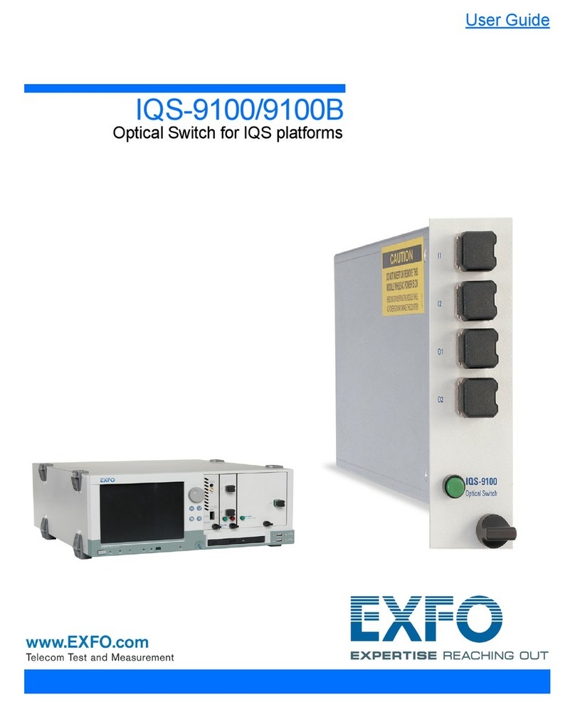
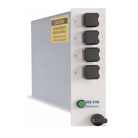
EXFO IQ-9100 User manual

IQ-9100
Optical Switch
Instruction Manual
October 1998
P/N: MAN-069-I .4ACE
Fourth Edition

!"
#
$%&!%&"
'(!'")*+%,
'-
./00+
12
#
2

CAUTION
!"

CONTENTS
iv IQ-9100
CONTENTS
Certification Information ...................................................................................................vii
1I
NTRODUCTION ..........................................................................................................................1-1
1.1 Presentation ...................................................................................................................1-1
1.2 IQ-200 Product Line .......................................................................................................1-1
1.3 Unpacking and Inspection ..............................................................................................1-2
1.4 Safety Conventions ........................................................................................................1-2
1.5 Transportation and Storage ...........................................................................................1-3
1.6 Getting Help ...................................................................................................................1-3
2P
RELIMINARY INFORMATION ......................................................................................................2-1
2.1 General Description .......................................................................................................2-1
2.2 Front Panel Description .................................................................................................. 2-3
2.3 Module Insertion ...........................................................................................................2-12
2.4 Optical Connections .....................................................................................................2-13
2.5 Module Removal ..........................................................................................................2-13
3O
PERATION ...............................................................................................................................3-1
3.1 Loading the Application Software ...................................................................................3-1
3.2 Main Window Description ............................................................................................... 3-5
3.3 Monitor Window ...........................................................................................................3-11
3.4 Exiting the Application Software ...................................................................................3-12
3.5 Using the Program Mode .............................................................................................3-13
4S
UGGESTED APPLICATIONS .......................................................................................................4-1
4.1 Multiple Device Testing ..................................................................................................4-1
4.2 Optical Switch Port Insertion Loss .................................................................................4-2
4.3 Creating Customized Switch Configurations ..................................................................4-3
5T
HE GPIB INTERFACE ...............................................................................................................5-1
5.1 Command Structure .......................................................................................................5-1
5.2 Common Commands .....................................................................................................5-2
5.3 System Commands ........................................................................................................5-8
5.4 Specific Commands .....................................................................................................5-13
5.5 Quick Reference Command Tree ................................................................................5-17
5.6 GPIB Error Messages ..................................................................................................5-18

CONTENTS
Optical Switch v
6M
AINTENANCE AND TROUBLESHOOTING .....................................................................................6-1
6.1 Module Maintenance ......................................................................................................6-1
6.2 Cleaning Fiber Ends .......................................................................................................6-1
6.3 Cleaning Optical Ports ....................................................................................................6-2
6.4 Troubleshooting ..............................................................................................................6-2
7T
ECHNICAL SPECIFICATIONS ......................................................................................................7-1
8W
ARRANTY ...............................................................................................................................8-1
8.1 General Information ........................................................................................................8-1
8.2 Liability ............................................................................................................................8-2
8.3 Exclusions .......................................................................................................................8-2
8.4 Certification .....................................................................................................................8-2
8.5 Service and Repairs .......................................................................................................8-2
GLOSSARY ......................................................................................................................GLOSSARY-1
INDEX ......................................................................................................................................INDEX-1

FIGURES
vi IQ-9100
FIGURES
Figure 2-1. Module Nameplate ...........................................................................................2-2
Figure 2-2. 1 ×2 Optical Switch Module ............................................................................2-3
Figure 2-3. 1 ×4 Optical Switch Module ............................................................................2-4
Figure 2-4. 1 ×12 Optical Switch Module ..........................................................................2-5
Figure 2-5. 1 ×16 Optical Switch Module ..........................................................................2-6
Figure 2-6. 1 ×32 Optical Switch Module ..........................................................................2-7
Figure 2-7. 2 ×2 Optical Switch Module ............................................................................2-8
Figure 2-8. 2 ×4 Optical Switch Module ............................................................................2-9
Figure 2-9. 1 ×N Optical Switch Principle .......................................................................2-10
Figure 2-10. 2 ×2 Optical Switch Principle ........................................................................2-10
Figure 2-11. 2 × 4 Optical Switch Principle ........................................................................2-11
Figure 2-12. Removing an IQ Module ................................................................................2-14
Figure 3-1. 1 ×2 Optical Switch Main Window ..................................................................3-1
Figure 3-2. 1 ×4 Optical Switch Main Window ..................................................................3-2
Figure 3-3. 1 ×12 Optical Switch Main Window ................................................................3-2
Figure 3-4. 1 ×16 Optical Switch Main Window ................................................................3-3
Figure 3-5. 1 ×32 Optical Switch Main Window ................................................................3-3
Figure 3-6. 2 ×2 Optical Switch Main Window ..................................................................3-4
Figure 3-7. 2 ×4 Optical Switch Main Window ..................................................................3-4
Figure 3-8. Main Window ...................................................................................................3-5
Figure 3-9. 1 ×N Monitor Window ...................................................................................3-11
Figure 3-10. 1 ×N Optical Switch Program Setting Window .............................................3-13
Figure 3-11. 2 ×2 Optical Switch Program Setting Window ..............................................3-13
Figure 3-12. 2 ×4 Optical Switch Program Setting Window ..............................................3-14
Figure 4-1. Multiple Device Testing Setup .........................................................................4-1
Figure 4-2. Reference Setup ..............................................................................................4-2
Figure 4-3. Insertion Loss Testing Setup ...........................................................................4-3
Figure 4-4. 2 ×16 Customized Switch Configuration .........................................................4-3
Figure 5-1. GPIB Error Message Format .........................................................................5-18

CERTIFICATION INFORMATION
Optical Switch vii
CERTIFICATION INFORMATION
'%3
4/5%%6'
'7
#
8
9 6
9
9 %
9 %:;'<
WARNING
#$%&'(%)(
%*+
':
:7
7
='* >
%'-

CERTIFICATION INFORMATION
viii IQ-9100
'%3
4?%

INTRODUCTION
Optical Switch 1-1
1I
NTRODUCTION
1.1 Presentation
!"
@0/))A @B))'A
C
8
9
9
9 :
9
' @0/))A'
@0/))
1.2 IQ-200 Product Line
' @B))
'21D @A @B))
'A:
' @B),
> @B)E:=
: @B)E
:= @B)E4%:%
@B))'A @A
!"##$%&

INTRODUCTION
1-2 IQ-9100
'()
1.3 Unpacking and Inspection
' @0/))8
9 @0/)) >
9 322
9 %@
9 ?%
9 2!"
9 1
' @0/))
62
@0/))
1.4 Safety Conventions
'8
WARNING 6( 7
-?
WARNING7
CAUTION 6( 7
?
CAUTION
7
IMPORTANT 6
2

INTRODUCTION
Optical Switch 1-3
%)
WARNING
",
1.5 Transportation and Storage
>
''
(
9 22
9 1
9 F
9 2
1.6 Getting Help
'%A&G8,)
+8))>
HE5&
<@%
&/>,&G
%
/+))EE,,0,E!=A%"
'8!H/+"E+,)B//
:8!H/+"E+,B/G)
I:
:
%$*>(
/))%
G+,5,JJ
'8,,/,HE,))B)
:8,,/,HE50)0,

'2

PRELIMINARY INFORMATION
Optical Switch 2-1
*
2P
RELIMINARY INFORMATION
2.1 General Description
' @0/))
'
!5)K;/B5KEB5K;
/B5K/))K;/H)K":
' @0/))
@0/))
9
9
9 ;
' @0/))
@B),> @B)E:=
' @0/))*
1 @A @B),
4% @B)E4%:%
6 @0/))8
9&43
9 6AB,B:
9 1*!-*2"
9 1??!??:"
4A 5%*+
@

PRELIMINARY INFORMATION
2-2 IQ-9100
*
'
Figure 2-1. Module Nameplate
,-%)
)
''
7!"
Table 2-1. Optical Switch Configurations
Model Number of
channels Number of
IQ slots
@0/)B /×B /
@0/)H /×H /
@0//B /×/B B
@0//E /×/E ,
@0/,B /×,B 5
@0/BB B×B /
@0/BH B×H B
Ver.
Mfg.
date
P/N
S/N
Made in Canada QST-94
465 Godin Ave.
Vanier, Que., Canada G1M 3G7
This device complies with part 15 of the FCC rules. Operation is
subject to the following two conditions: (1) this device may not cause
harmful interference and (2) this device must accept any interference
received, including interference that may cause undesired operation.
(identifying configuration
and connector type)
Serial number
Product version
Manufacturing date
Fiber type
Part number
IQ-91XX-XX
Fiber 9/125 µm
25634-IQ
A-1.0
October 1997

PRELIMINARY INFORMATION
Optical Switch 2-3
2.2 Front Panel Description
BBB+
Figure 2-2. 1
×
2 Optical Switch Module
,- ,
S1
IQ-9100
S2
C
OPTICAL SWITCH
Switch port 1 and 2
Common port
LED push button

PRELIMINARY INFORMATION
2-4 IQ-9100
Figure 2-3. 1
×
4 Optical Switch Module
S4
S2
S1
IQ-9100
S3
C
OPTICAL SWITCH
Switch ports 1 to 4
Common port
LED push button

PRELIMINARY INFORMATION
Optical Switch 2-5
Figure 2-4. 1
×
12 Optical Switch Module
S3
S1
IQ-9100
S2
S4
OPTICAL SWITCH
S7
S5
S6
S8
S11
S9
S10
S12
C
Common port
LED push button
Switch ports 1 to 12

PRELIMINARY INFORMATION
2-6 IQ-9100
Figure 2-5. 1
×
16 Optical Switch Module
S3
S1
IQ-9100
S2
S4
OPTICAL SWITCH
S7
S5
S6
S8
S11
S9
S10
S12
S15
S13
S14
S16
C
Common port
LED push button
Switch ports 1 to 16

PRELIMINARY INFORMATION
Optical Switch 2-7
Figure 2-6. 1
×
32 Optical Switch Module
IQ-9100
OPTICAL SWITCH
S3
S1
S2
S4
S7
S5
S6
S8
S11
S9
S10
S12
S15
S13
S14
S16
S19
S17
S18
S20
S23
S21
S22
S24
S27
S25
S26
S28
S31
S29
S30
S32
C
Common port
LED push
button
Switch ports
1 to 32

PRELIMINARY INFORMATION
2-8 IQ-9100
Figure 2-7. 2
×
2 Optical Switch Module
O1
I1
IQ-9100
I2
O2
OPTICAL SWITCH
LED push button
Input ports
Output ports
I1 and I2
O1 and O2
Table of contents
Other EXFO Switch manuals
Popular Switch manuals by other brands
NETGEAR
NETGEAR S350 Series installation guide

Vision Octane
Vision Octane OCT3 Configuration guide
Syba
Syba SY-KVM20050 user guide
Delta Controls
Delta Controls S24 Installation, operation & maintenance instructions
D-Link
D-Link DUB-H4 - Hub - USB installation guide
Speaka Professional
Speaka Professional 2273674 operating instructions
Radware
Radware Alteon 5208 Memory upgrade procedure
Versitron
Versitron Web Smart+ SG71070M user manual
Exsys
Exsys EX-1190HMVS-PD manual
Microchip Technology
Microchip Technology Microsemi PDS-408G Web management user guide

TMB
TMB ProPlex GBS user manual

Rextron Technology, Inc.
Rextron Technology, Inc. AcroGear Series manual
