Exhausto NFO Sinus Optimal User manual

NFODrivesAB20211201016‐2QuickInstallationGuide
Quick Installation Guide
NFO Sinus Optimal
1 Mechanical installation
When unpacking the inverter, carefully inspect the product and make sure it has not been damaged during
transportation. An inverter with cracks, dents or other visual damage shall not be installed.
The inverter must not be installed so that outlet air from another inverter or other equipment blows directly
into the inverter air intake. A minimum of 80 mm clearance must be kept above and below the inverter.
All terminals are accessed by opening the plastic cover. To be able to use the snap-and-hold-open
functionality of the cover, a free space of 200 mm is required above the inverter.
During installation it is important that no foreign objects, such as cable strands or screws, fall into the
inverter as a short circuit may occur. Drilling in chassis or cover is not allowed.
After installation, make sure all grommets at the cable entries are mounted and that the cover is closed and
secured with its screws to avoid access to dangerous voltages.
1.1 Mounting
Unscrew the two lower captive screws and loosen the inverter from the backplate.
Fasten backplate to a vertical surface using four screws. Make sure that the top mounting screws are
sufficiently strong to hold the entire weight of the inverter.
Place the inverter on the backplate by mating the chassis cut-out to the backplate hooks. Tighten the lower
captive screws on both sides.
3006468-2022-04
NFODrivesAB20212201016‐2QuickInstallationGuide
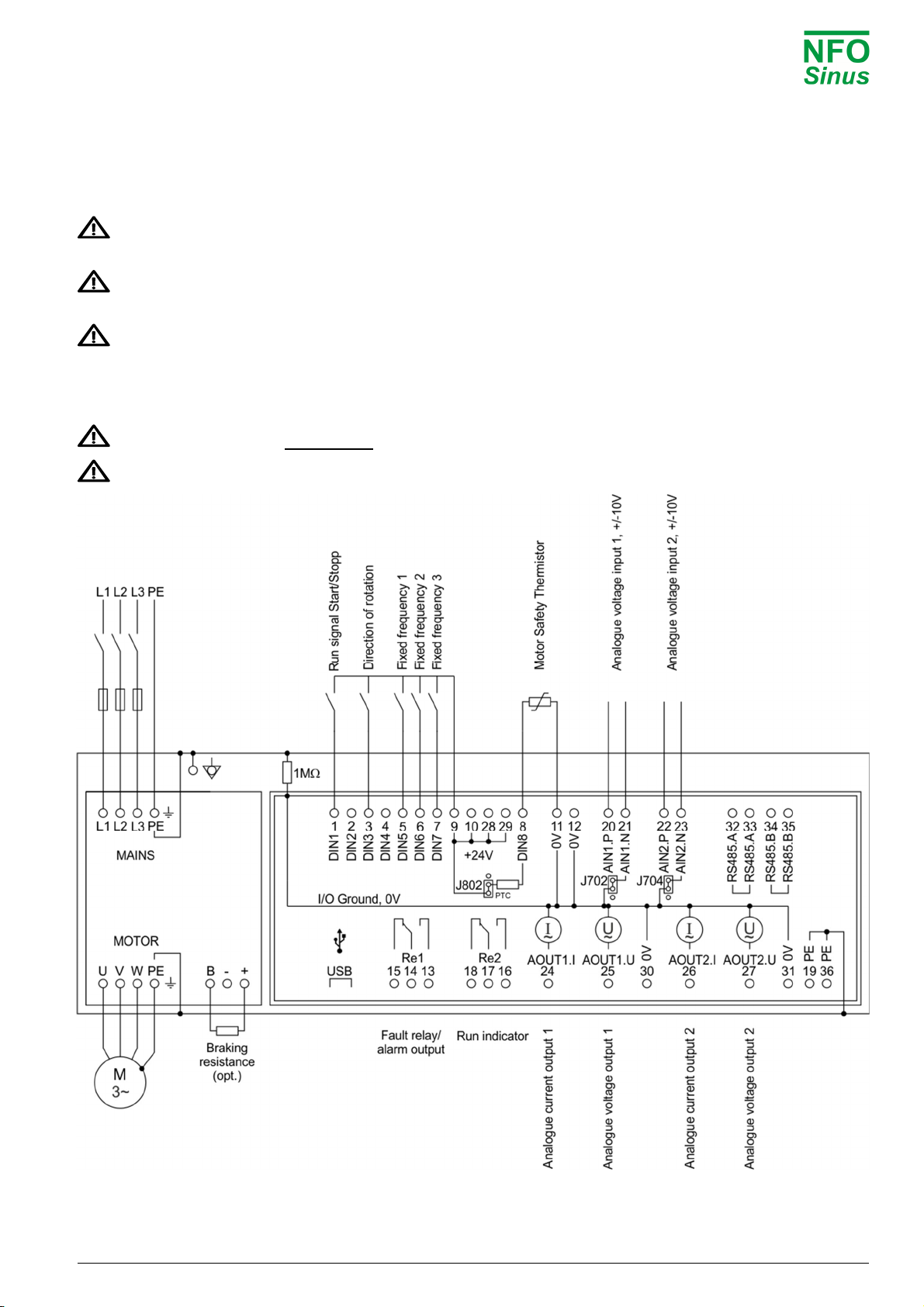
2 Electrical installation
Connect mains power to terminals L1, L2, L3 and PE.
Connect motor cable to terminals U, V, W and PE using standard unshielded cable.
Never install contactors or switches between the inverter (terminals U, V and W) and the motor that
intentionally or unintentionally may be used to disconnect the motor from inverter output.
A motor safety switch can be mounted between the inverter (terminals U, V and W) and the motor, but it
must only be operated when the motor is not running.
First time powered up, the installer must select application, enter motor name plate data, and perform a
motor tuning (see next section).
Connect/install the necessary low voltage signalling that is required for your application, e.g. a run signal
for start/stop, analog input for setpoint, communication, etc.
Make sure run signal is not activated until installer has completed the setup of the inverter.
Make sure the low voltage signal wires have sufficient isolation when passing nearby power cables.
3006468-2022-04

NFODrivesAB20213201016‐2QuickInstallationGuide
3 Initial setup and tuning
3.1 Select application
First time powered up after installation, or after performing a factory reset of parameters, the installer will be
prompted to select application type for the inverter.
The purpose of selecting application is to preset acceleration and deceleration ramps to a value suitable for
the application in question.
Please note that the preset values are a merely suggested general values. Depending on other operating
conditions, the installer may have to further adjust the accel/decel ramps.
Application Description
Pump Set acceleration and deceleration ramps suitable for general pump applications
Ventilation / other Set acceleration and deceleration ramps suitable for ventilation fan applications
OEM vacuum pump To be used only with OEM vacuum pump application
3.2 Enter motor data and perform tuning
First time powered up after installation, or after performing a factory reset of parameters, the installer must
enter the motor name plate data. The motor data is entered in the parameter group Motor and consists of
P-nom, U-nom, f-nom, N-nom, I-nom and cos . The data can be read from the motor name plate.
After motor data is entered, the installer must perform a motor tuning during which the inverter measures
and calculates the electrical properties of the motor. The tuning command is located in parameter group
Motor, adjacent to the motor data values. Select ‘Full’ tuning for most thorough measurement.
Until a correct tuning is performed, the inverter will toggle the status message ‘Not Tuned’ on the display.
Please refer to the Operating and Installation Manual for a complete description of the tuning commands.
3.3 Check rotation direction
After selecting application, entering motor data and performed tuning, it may be necessary to check/verify
correct rotation direction of the rotor.
This can be done by starting the motor at a low speed in manual mode.
Manual mode is selected when lower right corner of display reads ‘Manual’.
Pressing the ‘MAN / AUTO’ button toggles between manual and auto mode.
Pressing ‘START’ button in manual mode starts the motor.
Direction of rotation can be changed by changing the parameter ‘Phase order’ in parameter group ‘Run’.
The motor must be stopped when changing this parameter.
Default setpoint frequency in manual mode is 10.0 Hz. If necessary, increment or decrement setpoint using
the arrow up/down buttons.
When ready, press ‘STOP’ and then press the ‘MAN / AUTO’ button to select ‘Auto’mode. The inverter is
now ready to start operating according to the connected control signals.
3006468-2022-04

NFODrivesAB20214201016‐2QuickInstallationGuide
Keyboard and menu summary
Button Function
Enter into parameter or parameter-group.
Save parameter.
Enter/toggle between normal screen and setup
menu tree.
Leave parameter, parameter-group or leave
parameter unsaved.
Toggle Operating mode between Manual and Auto.
Starts motor in Auto mode if Run signal active.
Starts motor in Manual mode.
Stops motor in all modes.
NOTE: A bus master may start motor at any time
Increase parameter when changing.
Moves between parameter-groups or parameters.
Decrease parameter when changing.
Moves between parameter-groups or parameters.
Motor Ramp Run Control Freq. Speed PI-reg Output Comm. Status Temp. Display Count. Version Error
P-Nom Accel
Time
Phase
orde
r
Control
mode
Operate
mode
Operate
mode
Operate
mode
Relay 1
Mode
RS485
bustype U-rms Motor
temp
Display
par.1
Operate
time
CoProc
version Error-log
U-Nom Decel
Time
Stop
mode
Auto-
start FixFrq1 FixSpd1 FixReg1 Relay 1
Freq
RS485
add
r
I-rms Power
module
Display
par.2
Run
time
DSP
version
Restart
Delay
f-Nom Ramp
Brkpoint
Energy
save
A.input
1 type FixFrq2 FixSpd2 FixReg2 Relay 2
Mode
RS485
baud P-out COP
temp
Display
par.3
Brake
time
GUI
version
Reset
Time
N-Nom Alt.
Accel
Pwr On
delay
A.input
2 type FixFrq3 FixSpd3 FixReg3 Relay 2
Freq
RS485
cha
r
PF Heat
sink 1
Bklight
level
Cur.lim
time
Prod
date AC Fail
I-Nom Alt.
Decel
Run
delay
D.input
config FixFrq4 FixSpd4 FixReg4 Aout 1
Mode
RS485
timeout DC Link Heat
sink 2
Bklight
timeout
DC low
time
Serial
numbe
r
Temp Hi
cos Stop
delay FixFrq5 FixSpd5 FixReg5
Aout 1
Max
RS485
autostop
Brake
chop
Heat
sink 3
Menu
readonly
Start
count
PTC
Temp
Tuning DC
brake FixFrq6 FixSpd6 FixReg6
Aout 2
Mode
RS485
failsafe
Stator
freq.
Heat
sink 4
Alarm
count
Over
load
R-stator Kp
speed FixFrq7 FixSpd7 FixReg7
Aout 2
Max
USB
bustype
Rotor
freq.
Fan 1
volt
Output
Energy Ain Fail
R-rotor Ti
speed
A.input
min freq
A.input
min rpm
Setpoint
min
Analog
1 out
USB
add
r
Control
freq.
Fan 2
volt
Total
Energy DC Low
L-main Sleep
freq.
A.input
max freq
A.input
max rpm
Setpoint
max
Analog
2 out
USB
timeout
Rotor
speed
Fan 3
volt DC High
Sigma Bypass
freq.
Actual
min
USB
autostop
Control
speed
Fan 4
volt
GND
Fail
I-magn Bypass
bandw.
Actual
max
ABCC
interface
Actual
Torque
EXT
24V
Short
Circuit
I-limit Boost
time
Setp
min limit
ABCC
bustype
Control
Torque
USB
5V
Imagn
Low
Pole
Count
Boost
level
Setp
max limit
ABCC
add
r
Actual
PI-reg
Current
Low
T-nom Reg
sign
ABCC
timeout
Setpoint
Pi-reg
Current
High
Tuned
status
Reg
Kp
ABCC
autostop Ain 1 V Current
Limit
Reg
Ti
Auto
reset Ain1 mA Run Fail
Min freq Ain 2 V
Max freq Ain2 mA
Unit Keybrd.
Off limit Terminal
On limit
3006468-2022-04
Other Exhausto DC Drive manuals

Popular DC Drive manuals by other brands

Seagate
Seagate ST3780A product manual

YASKAWA
YASKAWA LA500 Installation and operation instruction

SEW-Eurodrive
SEW-Eurodrive Movidrive MDX61B System manual

Rockwell Automation
Rockwell Automation Allen-Bradley PowerFlex 750 Series Reference manual

Rockwell Automation
Rockwell Automation Allen-Bradley 1397 user manual

VST
VST SuperDisk Drive user guide


