QUICK START COMMISSIONING GUIDE
UNIDRIVE SP
Winding/unwinding solution with analogue references
4
3787 en - 03.2006 / a
LEROY-SOMER
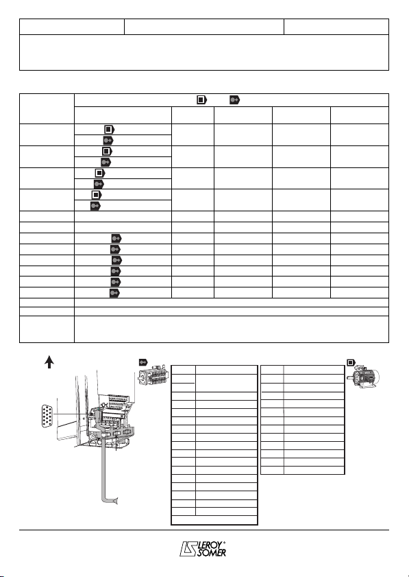
1 - GENERAL INFORMATION
The SP EDL ANA solution offers all winding/
unwinding functions maintaining a constant
tension of the product.
It comprises :
- a UNIDRIVE SP variable speed drive,
- a SM-EDL ANA module.
Note : If the Winding-unwinding solution is
managed by a field bus (use of a SM-Field
bus module), see the complete manual that
may be created from the CD Rom supplied
together with the drive.
1.1 - Operating principle
The system operates exclusively in closed
loop and it must be used with an asynchro-
nous or with a synchronous motor with all ty-
pes of encoders.
With an axial drive, in order to preserve a
constant tension on the product, irrespective
of the coil diameter, it is necessary that the
torque produced by the motor increases pro-
portionally to the radius.
The tension reference given by a potentio-
meter is applied through an analogue input.
By means of the line speed applied on ano-
ther analogue input and of the angular speed
issued from the encoder, a radius calculation
is made.
The tension reference multiplied by the ra-
dius determines the torque that the motor
must supply.
To refine the adjustment of the tension on the
product, it is possible to compensate the los-
ses without load (mechanical losses) and the
inertia during the transient periods.
1.2 - Operating modes :
- speed adjustment : product threading,
- traction adjustment : winding or unwinding.