Exide GEL G85 User manual

The EXIDE GEL Guarantee
If the operating instructions in this Battery Passport are
obeyed, the guarantee on materials and/or manufactu-
ring defects is 24 months from the date of sale. There is
no guarantee in the event of incorrect charging technique
(see page 8), incorrect use or mechanical stresses excee-
ding the Standard DIN-EN 60095 Part 1 Vibration
Strength 20 h/6 g.
EXIDE Automotive Batterie GmbH
Im Thiergarten
D-63654 Büdingen, Germany
Tel.: +49 (0) 60 42 / 81 - 545
Fax: +49 (0) 60 42 / 81 - 221
www.exide.de
Hints and Tips
for long battery life
A good choice!
2
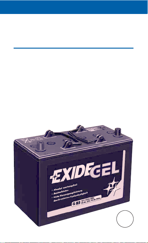
Congratulations on choosing an EXIDE GEL battery. As
a power supply battery for professional needs, the
EXIDE GEL provides more usable capacity and therefore
the best safety in power supply. When used in leisure
and sport it ensures the highest possible level of inde-
pendence. To keep your new EXIDE GEL in best conditi-
ons for a long service life, please read and obey the
instructions for use given below.
The best way is to keep your EXIDE GEL Battery Passport
with you where the battery is – on board. Then you’ll
always have it handy. The purchase data opposite must
always be stated in the event of a warranty claim.
* German Lloyd, Approval No. 15828-00HH on 29.06.2000
GL
*

3
First name/Name:
Purchase date:
Battery type:
Series Code No.:
– Dealer’s stamp –
Good for the environment!
By purchasing your EXIDE GEL you have acquired a bat-
tery that is particularly clean, safe and environmentally fri-
endly in manufacture and use. Make your contribution to
environmental protection and dispose of the battery at the
end of its life through a specialist dealer. He is obliged to
take back the battery. That allows your EXIDE GEL to be
recycled and returned to the circulation of reusable mate-
rials.

Your EXIDE GEL is ABSOLUTELY
MAINTENANCE-FREE!!
During the entire battery lifetime there is no need for you
to check the acid level, grease the terminal posts or top up
with distilled water.
These benefits are a result of the sealed construction of the
EXIDE GEL.
But that also means: you must never open the battery!
Otherwise the battery would be destroyed by oxidation.
For the case if your battery is installed where an exter-
nal charger is necessary:
“Absolutely maintenance-free” does not mean that you
can neglect your EXIDE GEL battery as far as charging with
the charger is concerned! Correct recharging (IU-charge
characteristic) is the only way to preserve the performance
benefits of your EXIDE GEL for a prolonged time.
Installation
4
Switch off all power-consuming equipment, and connect the
earth/ground/chassis cable last of all. Take care to ensure
that the battery and its connections are secure. Your GEL
battery is supplied from the manufacturer ready for use!
➡CAUTION: In spite of the extremely small amount
of gassing from your GEL battery, please pay atten-
tion to the following:
• Do not use hermetically sealed battery containers.
• There should be no spark-producing switches, relays or
the like situated in the immediate vicinity of the battery.
Technological advantages
5
As a result of its future-proofed technology with an immo-
bilised gel electrolyte, your EXIDE GEL is not only absolu-
tely maintenance-free but also
• absolutely electrolyte-tight • permitted angle of inclina-
• vibration-resistant tion up to 180 degrees
• extremely low gassing • deep-discharge-proof
• cycling-proof (recharge after a maxi-
mum of 4 weeks)
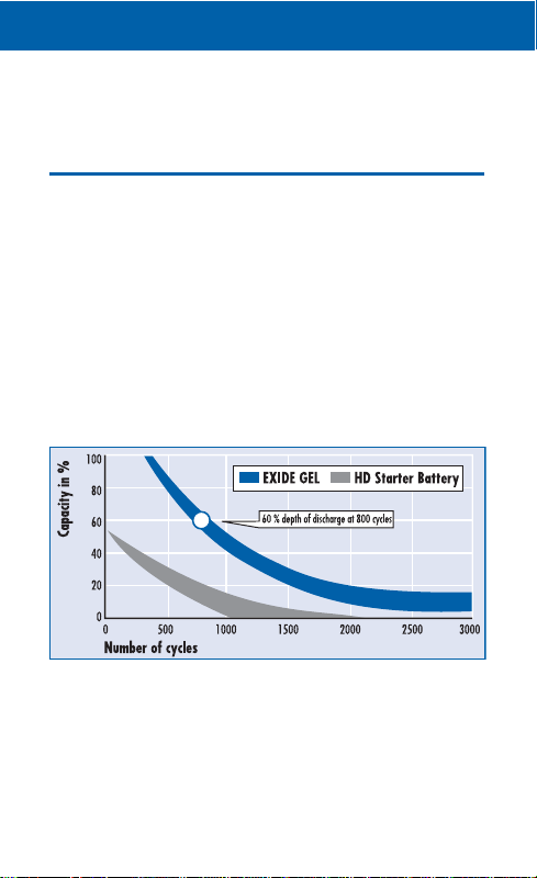
More cycles – longer lifetime:
Compared to an HD-commercial vehicle starter battery,
the EXIDE GEL allows a much greater number of cycles at
the same depth of discharge. A clear advantage in regard
to performance and economy.

What you need to know!
6
Every accumulator is an electric current storage device
with a limited capacity. The difference compared to elec-
tricity from a mains socket is that the energy taken out of
the battery must be 100% returned to it again! Insufficient
recharge leads to a “negative charge balance”. Problems
up to premature failure of the battery can be expected.
As a rule, the lighting generator is the only available
accessory for recharging the battery while underway.
However, the lighting generator and solar panel are only
supporting charging devices.
100% recharge is possible only with a suitable charger
operated via an external mains supply. That’s the reason
why conscious and economical use of the energy supply
should be as self-evident as the conserving use of natural
resources (drinking water etc.): No battery yields an
inexhaustible supply!
➡HINT: Make an energy balance for all electricity-con-
suming equipments on board. This allows you to check
the amounts of energy used each day and which must
therefore be supplied to the battery again.
Example calculation for a refrigerator:
Power 42 Watts (W): Voltage 12 Volts (V)
= current 3.50 Amperes (A)
x duration of use/day in hours (h) e.g. 8 hrs.
= required capacity in Ampere-hours (Ah)
e.g. 28 Ah

Therefore:
7
The highest standards of reliability and economy are
imposed in professional use, e.g. buses for local public
transport. The recommendation in order to keep the EXIDE
GEL in a good state of charge at all times is:
recharge at least 1x per week!
The following recommendations apply for use in the leisure
and sports area:
• Always start your journey with a fully charged battery!
• During the holiday, use every opportunity to recharge
the battery via the built-in on-board charging equipment!
• After the end of the journey, it is essential that the bat-
tery is charged via the on-board charger equipment
for longer than 12 hours, since as a rule the battery is
not fully recharged even during prolonged mobile use
(return journey).
•Before prolonged periods out of use, e.g. the winter
break, the battery must again be fully charged for longer
than 12 hours. Then disconnect the positive terminal post!
➡Following this example, you can determine the total ca-
pacity needed for all of the electricity-consuming equip-
ments on board by addition (you will find the power
data in Watts on rating plates, lamp holders etc.).
➡ Multiply the total Ah value determined by the EXIDE
GEL safety factor of 1.3 (it is much higher for conven-
tional batteries) and you will know what effective
capacity the GEL battery used should have. If your on-
board network is under-supplied, a more powerful
EXIDE GEL battery and/or an additional power supply
battery will help (p. 15).

What you must pay attention to!
8
External charging:
Charge with an unsuitable charger, e.g. one that switches
off after reaching a charging voltage of 14.1 – 14.4 V,
leads to severe sulphating of the battery plates and thus to
battery “starvation”.
The correct charging technique:
Characteristic curve IU or IU0U1, i.e. “I” phase at a mini-
mum of 1/10th of the battery capacity as the charging cur-
rent (e.g. 8 A for a G 80).
After reaching the charging voltage of 14.1 – 14.4 V,
switchover to the “U” phase (main charging phase)
oat14.1 – 14.4 V takes place. The total charging time
must be at least 12 hours, even if the battery was only
slightly discharged. After that the charger can be switched
off (= IU characteristic curve) or switched over to float
charge (IU0U1).
The voltages mentioned above apply for a 12 V on-board
electric system. The data is doubled for a 24 V on-board
electric system.
Your alternative charging
configurations
9
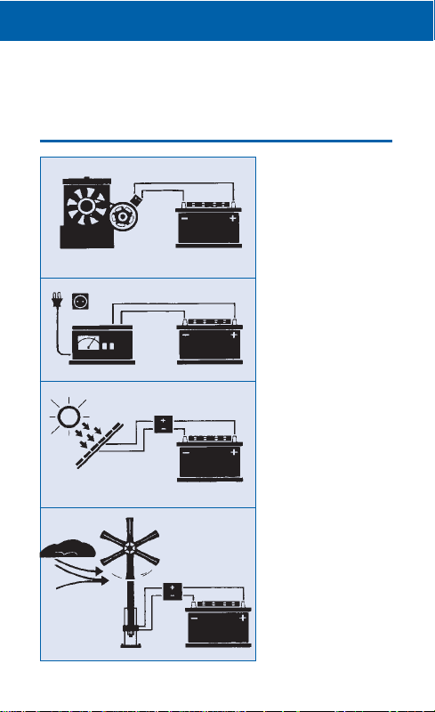
Permitted charging
voltage
1. Generators with
controllers
• 14.1 to 14.4 V for 12 V
• 28.2 to 28.8 V for 24 V
2. Chargers
(according to the data
quoted on the previous
page)
• 14.1 to 14.4 V for 12 V
• 28.2 to 28.8 V for 24 V
3. Solar panels
(with appropriate
voltage regulators)
• 14.2 V constant
4. Wind or wave generators
(with appropriate
voltage regulators)
• 14.2 V constant
The voltage values stated in
each case are set-point
values for the voltage
at the battery terminals.

What can cause the power
10
1. Negative charging balance ➯capacity loss ➯battery
failure
• insufficient charging time (less than 12 hours) via the
on-board charger
• insufficient recharge via the lighting generator because
of low voltage (voltage losses in the on-board electricity
system or faulty/incorrectly set voltage controller)
• faulty charger
• unsuitable charger
• negative energy balance caused by too many retrofitted
electricity-consuming equipments, i.e. the energy con-
sumption is larger than the capacity charged in

11
2. Deep discharge
Possible causes of deep discharge:
• consuming equipments not switched off
• leakage discharge in the milliampere region in spite of
the main switch being switched off, e.g.
– caused by an electromagnetic isolation valve in the
heating system
– caused by a solar controller (output)
– caused by the on-board control panel
– caused by silent consumers (e.g. clock, signal lamps,
LED displays)
Example:
Silent consumers can have a current consumption of
approx. 55 milliamperes. This means that approx. 1.32
Ah is taken from the battery during one day. Thus a fully
charged 80 Ah on-board battery will be completely
discharged after about 2 months.
Possible consequential damage:
Despite recharging, only a fraction of the theoretical char-
ge capacity remains available for withdrawal.
In the worst case, the battery is already destroyed by a
short-circuit in one of the battery cells.
supply battery to fail?

Correct energy precautions
12
In contrast to conventional batteries, which can survive
only 1 – 2 days in a deeply discharged condition, your
EXIDE GEL battery tolerates deep discharge up to a maxi-
mum of 4 weeks!
Thereafter it should be charged for at least 48 hours at
14.1 – 14.4 V (cf. charging technique, p. 8).
➡always switch off consuming equipment that is not nee-
ded!
➡take silent consumers into account when calculating the
energy consumption!
➡recharge the battery for at least 48 hours after a deep
discharge!
Self-discharge
(independent of continuous consumers of electricity):
The loss of power of an EXIDE GEL through self-discharge
is extremely small: at 20 - 25°C it loses 0.1 % of the bat-
tery capacity/day. However, the self-discharge increases
remarkable as the temperature rises: at 35°C it is
0.7%/day, i.e. 7 times more!
Summer use
In summer the higher self-discharge as a result of the tem-
perature, combined with continuously consuming equip-
ments without recharging via the on-board charging
system, can lead to deep discharge of the battery particu-
larly quickly.
Therefore we recommend:
➡Recharging once per month
➡

13
CHECKLIST Causes of failure:
The causes of failures often lie in the on-board electric
system, and you can easily trouble-shoot them and correct
them yourself. If problems arise, you should check the fol-
lowing points in particular:
• charging voltage at the battery terminals too low
(below 14.1 V)
• faulty lighting generator
• excessive charging voltage (over 14.4 V) caused by a
faulty voltage controller (excessive charging voltage
leads to destruction of the battery)
• slack vee belts
• oxidised or loose connection terminals
• faulty switching relay of an electricity-consuming equip-
ment
• short circuit in the on-board electrical system
• leakage currents in the on-board electrical system
To check the battery condition, it is advisable to carry out
an open circuit voltage measurement as described below.
➡BASIC PRINCIPLE: Fully recharge of the battery
and disconnection of the positive terminal before any
prolonged idle period.

Measurement of the open cir-
cuit voltage (OCV)
14
The measurement of the open circuit voltage is a simple
and effective method for checking the condition of the bat-
tery. “OCV” is understood to mean the voltage of the
charged battery in a quiescent state, without any current
being supplied or drained. As a rule a built-in voltmeter is
present for this measurement in mobile homes and boats.
If this is not available, an external instrument can be
purchased at very small cost from a specialist dealer.
➡The measurement should take place 24 hours after the
last charge at the earliest. The battery must not be loa-
ded in the meantime, i.e. no current must be drained.
Quiescent voltage in V State of charge in %
> 12.8 100
12.55 75
12.3 50
12.2 25
< 12.0 0

Enlarging the on-board
electrical system
15
If it is necessary to retrofit a second battery for the on-
board electrical system, then the following basic rules
apply:
Combination Connected in series Connected in parallel
Wet battery not possible! possible, with
+ gel battery isolation relay
Gel battery possible! possible!
+ gel battery
New battery possible, with a possible, with a
+ old battery maximum age diffe- maximum age diffe-
rence of 1 year rence of 1 year
Large + small not possible! possible, if the con-
battery nection cable cross-
sections are the same
(capacity ratio up to
1:3)
➡
Check the capacity of the charger equipment!
Rule of thumb: At least 1/10th of the battery capacity is
needed, plus consuming equipments in use during the
charging process (cf. p. 8, “The correct charging techni-
que”).
Our recommendation: The faultless technical condition of
your vehicle is the best pre-condition for safe, problem-
free use. Have your vehicle maintained regularly by a
professional engineer. A thorough vehicle check before
starting your holiday will largely safeguard you against
unpleasant surprises.

Correct jump starting . . .
16
1.Use the correct jump start cable for petrol engines and
diesel engines.
2.The capacity of the starter battery delivering current
(e.g. 45 Ah) must not be significantly less than that of
the discharged starter battery.
3.Only batteries of the same nominal voltage (e.g. 12 V)
can be connected together using the jump leads.
4.No bodywork contact must exist or be set up between
the vehicles.
5.Sources of ignition (e.g. open flame, burning cigars,
cigarettes or electric sparks) must be kept away from
the starter batteries (danger of explosion).
6.Keep distance from the starter batteries (danger of che-
mical burns). The electrolyte of the discharged wet bat-
tery is liquid even at sub-zero temperatures.
7.The discharged starter battery must not be disconnected
from its associated on-board electrical system during or
for a jump-start.
8.Switch off the vehicles’ ignitions before connecting the
jump-start cable. Handbrakes must be set. With manual
gearboxes, put the gear lever in the idle (disengaged)
position, and with automatic gearboxes put the selector
lever in the “P” position.
9.Lay the jump lead cables in such a way that the rota-
ting parts in the engine compartment cannot touch
them.
17
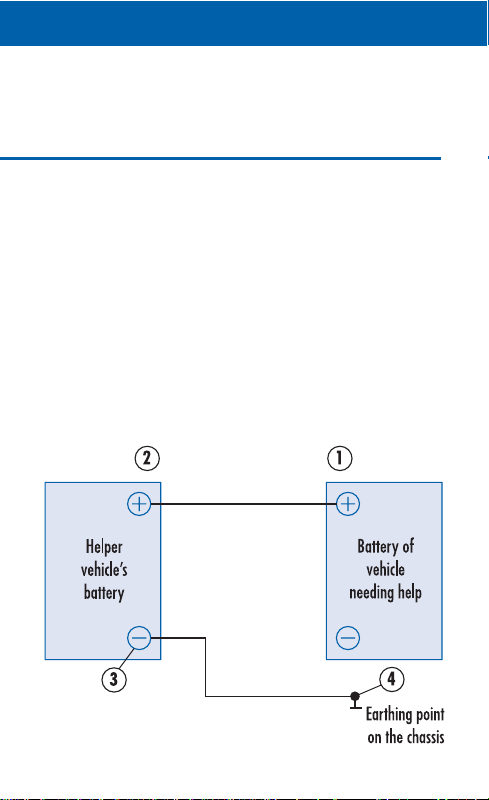
10. Connecting and disconnecting the jump lead cables:
a) Connecting
First of all connect the cable with red terminal clamps to
the positive pole of the discharged starter battery (see
Figure, Position 1) and then to the positive pole of the
donor battery (see Figure, Position 2).
Next connect the cable with black terminal clamps to the
negative pole of the donor battery (see Figure, Position 3)
and then to the vehicle chassis of the broken-down vehicle,
e.g. to the earthing strap or some other bare metal point
on the engine block (see Figure, Position 4) as far away
as possible from the starter battery, to prevent ignition of
any explosive gas mixture that may have been evolved.

Correct jump starting . . .
18
b) Starting
After connecting the jump lead cables, the engine of the
donor vehicle must be started and set to medium revolu-
tion speed. Next the engine of the broken-down vehicle is
started. After each attempted start, which must not last
longer than 15 seconds, a waiting time of at least 1 minute
must be interposed. After successfully starting the engine
of the broken-down vehicle, wait 2 to 3 minutes until it is
running smoothly.
c) Disconnecting
Disconnect the jump lead cables in the reverse of the
connection sequence: first remove the black terminal
clamp from the earthing strap or engine block (see Figure,
Position 4) of the broken-down vehicle. Then remove the
other black terminal clamp from the negative pole of the
donor battery (see Figure, Position 3). Next remove the
two red terminal clamps in any order (see Figure, Position
1 and 2). When removing the jump lead cables, take care
to ensure that they do not come into contact with the rota-
ting parts of the engines.
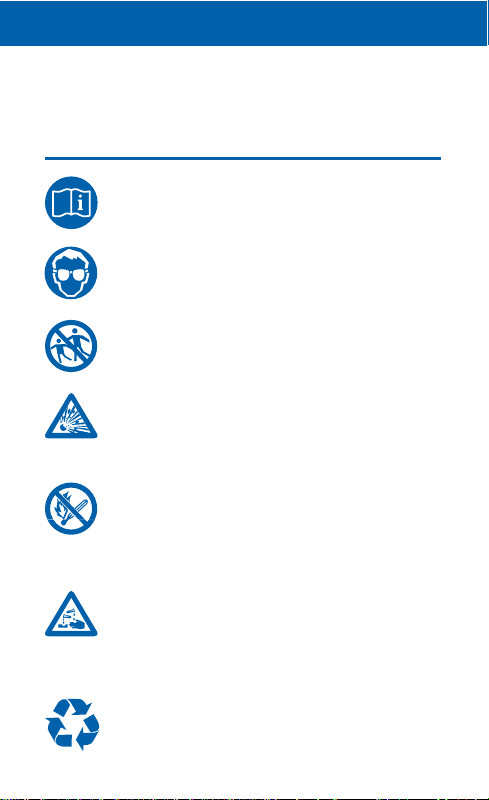
Explanation of warning symbols
19
Obey instructions on the battery and/or in the
instructions for use and in the vehicle operating
instructions
Wear eye protection
Keep children away from acids and batteries
Risk of explosion:
– A highly explosive mixture of hydrogen and
oxygen gases is evolved during battery char-
ging, therefore:
Fire, sparks, open flames and smoking are pro-
hibited:
– Avoid causing sparks when handling cables
and electrical equipments!
– Avoid short-circuits!
Danger of chemical burns: battery acid is extre-
mely corrosive, therefore:
– Wear protective gloves and eye protection
– Do not tilt batteries, acid can escape from
the gas vent openings
Disposal:
– Hand in old batteries at a collection depot.
Table of contents
Other Exide Camera Accessories manuals


Popular Camera Accessories manuals by other brands


Trojan
Trojan GC2 48V quick start guide

Calumet
Calumet 7100 Series CK7114 operating instructions

Ropox
Ropox 4Single Series User manual and installation instructions

Cambo
Cambo Wide DS Digital Series Main operating instructions

Samsung
Samsung SHG-120 Specification sheet

Ryobi
Ryobi BPL-1820 Owner's operating manual