Exide GNB Classis GroE User manual

Gebrauchsanweisung de 2–7
Instructions for use en 8–13
Notice d’utilisation fr 14–19
Manual de instrucciones es 21–25
Istruzioni per l’uso it 27–31
Gebruiksaanwijzing nl 32
Brugsanvisning da 32
Bruksanvisning no 32
Bruksanvisning sv 33
Instruções de utilização pt 33
Käyttöohje fi 33
Oδηγίες χρήσης el 34
Használati utasítás hu 34
Návod k použití cs 34
Návod na použitie sk 35
Инструкция по применению ru 35
Kasutamisjuhised et 35
Lietošanas instrukcija lv 36
Naudojimosi instrukcijos lt 36
Navodila za uporabo sl 36
Tagħrif ta Użu
mt
37
Notkunarleiðbeiningar fyrir
is 37
Упътване за употреба
bg 37
Instrucţiuni de utilizare
ro 38
Instrukcja eksploatacji pl 38
Kullanım Kılavuzu tr 38
Uputstvo za upotrebu sr 39
Uputa za uporabu hr 39
GroE
OPzS-LA
OCSM-LA
OGi-LA
Energy Bloc
GNB_Classic.indd 1 06.08.14 12:51

2
de
Nenndaten
Gebrauchsanweisung beachten und sichtbar in der Nähe der Batterie anbrin-
gen!
Arbeiten an Batterien nur nach Unterweisung durch Fachpersonal
Rauchen verboten!
Keine offene Flamme, Glut oder Funken in die Nähe der Batterie bringen, da
Explosions- und Brandgefahr!
Bei Arbeiten an Batterien Schutzbrille und Schutzkleidung tragen!
Die Unfallverhütungsvorschriften sowie DIN EN 50272-2, DIN EN 50110-1
beachten!
Säurespritzer im Auge oder auf der Haut mit viel klarem Wasser aus- bzw. ab-
spülen. Danach unverzüglich einen Arzt aufsuchen.
Kleidung mit Wasser auswaschen!
Explosions- und Brandgefahr, Kurzschlüsse vermeiden!
Elektrostatische Auf- und Entladungen/Funken sind zu vermeiden!
Blockbatterien/Zellen haben ein hohes Gewicht! Auf sichere Aufstellung achten!
Nur geeignete Transportmittel verwenden!
Block-/Zellengefäße sind empfindlich gegen mechanische Beschädigungen.
Vorsichtig behandeln!
Niemals Blockbatterien/Zellen an den Polen anheben oder hochziehen.
Achtung! Gefährliche elektrische Spannung.
Metallteile der Batteriezellen stehen immer unter Spannung, deshalb
keine fremden Gegenstände oder Werkzeug auf der Batterie ablegen!
Elektrolyt ist stark ätzend.
Bei Nichtbeachtung der Gebrauchsanweisung, bei Installation oder Reparatur mit nicht
originalen bzw. vom Batteriehersteller nicht empfohlenen Zubehör- bzw. Ersatzteilen,
eigenmächtigen Eingriffen, Anwendung von Zusätzen zum Elektrolyten (angebliche
Aufbesserungsmittel) erlischt der Garantieanspruch.
Pb
Gebrauchte Batterien müssen getrennt von Hausmüll gesammelt und recycelt werden
(EWC 160601). Der Umgang mit gebrauchten Batterien ist in der EU Batterie Richtlinie
(2006/66/EC) und den entsprechenden nationalen Umsetzungen geregelt
(hier: Batterie Verordnung).
Wenden Sie sich an den Hersteller ihrer Batterie, um Rücknahme und Entsorgung
der gebrauchten Batterie zu vereinbaren, oder beauftragen Sie einen lokalen
Entsorgungsfachbetrieb.
1. Inbetriebnahme
Die Inbetriebnahme sollte sobald als möglich
nach Erhalt der Batterie erfolgen. Ist dies nicht
möglich, so sind die Hinweise gem. Punkt 6. zu
beachten. Vor der Inbetriebnahme sind alle
Zellen auf mechanische Beschädigung, polrich-
tige Verschaltung und festen Sitz der Verbinder
zu prüfen. Für die Bauarten gelten folgende
Drehmomente:
ennsannung U: 2,0 V x Zellenzahl
ennkaaitt = C10 : 10 h Entladung (siehe Typschild und technische Daten dieser Anweisung)
ennentaestrom I= I10 : C/ 10 h
ntaeschusssannung US: siehe technische Daten dieser Anweisung
enntemeratur : 20 °C
Batterietyp: Anzahl Zellen/Blöcke:
Montage urch GB utragsnr. am
Inbetriebnahme durch: am:
Sicherheitskennzeichen angebracht durch: am:
GroE, OCSM-LA, Energy Bloc OGi-LA Zellen
OPzS-LA Zellen OPzS blocks ≤250 Ah ≥260 Ah
20 Nm 12 Nm 8 Nm 20 Nm
Tabelle 1: Drehmomente, alle mit einer Toleranz
von ± 1 Nm
Gegebenenfalls sind die Polabdeckkappen auf-
zubringen. Der Elektrolytstand aller Zellen ist zu
prüfen und falls erforderlich, auf maximalen
tan mit gereinigtem asser nach DI 3 530
ei u bringen. Batterie orichtig bei ausge-
schaltetem Ladegerät und abgeschalteten
Verbrauchern an das Ladegerät anschließen
(positiver Pol an positive Anschlussklemme).
Ladegerät einschalten und gemäß Punkt 2.2 la-
den.
Der Isolationswiderstand, gemessen bei abge-
trenntem Verbraucher und Stromversorgung,
muss ≥100 Ω ro Vot ennsannung betragen.
2. Betrieb
Für den Aufbau und Betrieb von ortsfesten Blei-
batterien git DI 50222.
Die Batterie ist so aufzustellen, dass zwischen
einzelnen Blöcken/Zellen eine umgebungsbe-
dingte Temperaturdifferenz von > 10 K nicht
auftreten kann. Der Zellen- bzw. Blockabstand
so 10 mm, bei chrankeinbau minestens 5
mm, betragen.
2.1 Entladen
Die dem Entladestrom zugeordnete Entlade-
schlussspannung der Batterie darf nicht unter-
schritten werden. Sofern keine besonderen An-
gaben des Herstellers vorliegen, darf nicht mehr
as ie ennkaaitt entnommen weren. ach
Entladungen, auch Teilentladungen, ist sofort zu
laden.
2.2 Laden
Anwendbar sind alle Ladeverfahren mit ihren
Grenzwerten gemäß
DI 13 IUenninie, Ikonst. 2,
Ukonst. 1
DI 1 enninie, 0,05 Vee
DI 16 Ienninie, Ikost. 2
Je nach Ladegeräteausführung und Ladegerä-
tekennlinie fließen während des Ladevorgangs
Wechselströme durch die Batterie, die dem
Ladegleichstrom überlagert sind. Diese überla-
gerten Wechselströme und die Rückwirkungen
von Verbrauchern führen zu einer zusätzlichen
Erwärmung der Batterie und Belastung der
Elektroden mit möglichen Folgeschäden (siehe
unkt 2.5. nagenbeingt kann bei ogenen
Betriebsarten gem. DI 50222 geaen
werden:
a) Bereitschaftsparallel- und Pufferbetrieb
Hierbei sind Verbraucher, die Gleichstromquelle
und die Batterie ständig parallel geschaltet.
Dabei ist die Ladespannung die Betriebsspan-
nung der Batterie und gleichzeitig die Anlagen-
spannung. Beim Bereitschaftsparallelbetrieb ist
die Gleichstromquelle jederzeit in der Lage, den
maximalen Verbraucherstrom und den Batterie-
ladestrom zu liefern. Die Batterie liefert nur dann
Strom, wenn die Gleichstromquelle ausfällt.
Siehe Tabelle 2 für die einzustellende Erhaltungs-
ladespannung, gemessen an den Endpolen der
Batterie. Zur Verkürzung der Wiederaufladezeit
kann eine Starkladestufe verwendet werden, bei
er ie aesannung 2,33 V 2, V nah er
Zellen beträgt (Bereitschaftsparallelbetrieb mit
Wiederaufladestufe). Es folgt eine automatische
Rückschaltung auf die Erhaltungsladespannung
gemäß Tabelle 2. Beim Pufferbetrieb ist die
Gleichstromquelle nicht in der Lage jederzeit den
maximalen Verbraucherstrom zu liefern. Der
Verbraucherstrom übersteigt zeitweilig den
ennstrom er Geich stromuee. hren ie-
ser Zeit liefert die Batterie den Strom. Die Batterie
Classic-Baureihe: GroE, OPzS-LA, OCSM-LA, OGi-LA, Energy Bloc
Gebrauchsanweisung
Ortsfeste geschlossene Bleibatterien
GNB_Classic.indd 2 06.08.14 12:51

3
de
ist nicht jederzeit voll geladen. Daher ist die
aesannung erbraucherabhngig au 2,25 V
2,30 V nah er een in bstim mung mit
dem Batteriehersteller einzustellen.
b) Umschaltbetrieb
Beim Laden ist die Batterie vom Verbraucher
getrennt. Die Ladespannung kann gegen Ende
er aung 2,6 V 2,5 V nah er een
betragen. Das Laden ist zu überwachen (siehe
kt. 2., 2.5 un 2.6 ach rreichen es Vo
ladezustandes ist die Ladung zu beenden oder
au rhatungsaen gem kt. 2.3 u scha
ten.
c) Batteriebetrieb (Lade- /Entladebetrieb)
Der Verbraucher wird nur aus der Batterie ge-
speist. Hierbei kann die Ladespannung der Bat-
terie gegen ne er aung 2,6 V 2,5 V
Anzahl der Zellen betragen. Das Laden ist zu
berwachen siehe kt. 2., 2.5 un 2.6 ach
Erreichen des Vollladezustandes ist die Ladung
abzuschalten. Die Batterie kann je nach Bedarf
auf den Verbraucher geschaltet werden.
2.3 Erhalten des Vollladezustandes
(Erhaltungsladen)
Es sollten Geräte mit den Festlegungen nach
DI 13 benutt weren. ie sin so einu
stellen, dass die mittlere Zellenspannung dem
Wert in Tabelle 2 entspricht. Die Elektrolytdichte
sollte über längere Zeit nicht sinken.
2.4 Ausgleichsladung
Wegen möglicher Überschreitungen der zuläs-
sigen Verbraucherspannungen sind entspre-
chende Maßnahmen zu treffen, z.B. Abschalten
der Verbraucher.
Eine Ausgleichsladung ist nach einer Tiefentla-
dung und/oder nach ungenügenden Ladungen
erforderlich. Sie können wie folgt durchgeführt
werden:
bstan konstanter annung on ma.
2, Vee bis u 2 tunen,
mit I oer enninie gem. kt. 2.6.
Bei berschreiten er ma. emeratur on 55
°C ist das Laden zu unterbrechen oder vorüber-
gehend auf Erhaltungsladen zu schalten, damit
die Temperatur absinkt. Das Ende der Aus-
gleichsladung ist erreicht, wenn die Elektrolyt-
dichten und die Zellenspannungen innerhalb von
2 Stunden nicht mehr ansteigen (2 h-Kriterium
gilt nur beim Laden mit I- bzw. W-Kennlinie).
2.5 Überlagerte Wechselströme
hren es ieerauaens bis 2, Vee
gemäß den Betriebsarten Punkt 2.2 darf der Ef-
fektivwert des Wechselstromes zeitweise max.
10 e 100 h ennkaaitt betragen. ach
dem Wiederaufl aden und dem Weiterladen
(Erhaltungsladen) im Bereitschaftsparallelbetrieb
oder Pufferbetrieb darf der Effektivwert des
echsestromes 5 e 100 h ennkaaitt
nicht überschreiten.
2.6 Ladeströme
Im Bereitschaftsparallelbetrieb oder Pufferbetrieb
IUaeerahren mit Spannungen bis zu
2, Vee sin ie ae ströme nicht begrenzt
ichtwerte 10 bis 35 e 100 h ennkaazi-
tät). Beim Ladeverfahren mit I- oder W-Kennlinie
weren 2, Vee berschritten, erbunen mit
höherer Wasserzersetzung. Die in der nachfol-
genden Tabelle angegebenen Ladeströme je
100 Ah ennkaaitt ren nicht berschritten
werden.
2.7 Temperatur
Der empfohlene Betriebstemperaturbereich für
Beibatterien betrgt 10 bis 30 . e techni
schen Daten geten r ie enntemeratur
20 °C. Der ideale Betriebstemperaturbereich
betrgt 20 5 . here emeraturen er
kr en ie Brauchbarkeitsauer. ierigere
Temperaturen verringern die verfügbare Kapazi-
tät. Das Überschreiten der Grenztemperatur von
55 ist unussig.
2.8 Temperaturabhängige Ladespannung
Innerhalb der Betriebstemperatur von 10 °C bis
30 ist eine temeraturabhngige nassung
der Ladespannung nicht erforderlich. Bei Tem-
e raturen keiner as 10 oer grer 30 so
eine temperaturabhängige Anpassung der Lade-
spannung erfolgen.
Der emeraturkorrekturaktor betrgt 0,00 V
ee e . Dabei ren 2, V nicht berschrit-
ten un 2,15 V OM 2,1 V nicht unter-
schritten werden.
2.9 Elektrolyt
Der Elektrolyt ist verdünnte Schwefelsäure. Die
enneektrotichte 0,01 kg gem techn.
Daten) bezieht sich auf 20 °C im vollgeladenen
Zustand und maximalem Elektrolytstand. Höhere
Temperaturen verringern die Elektrolytdichte, tie-
fere Temperaturen erhöhen die Elektrolytdichte.
Der zugehörige Korrekturfaktor beträgt
0,000 kg e .
Beisie ektrotichte on 1,23 kg bei 35
entsricht einer Dichte on 1,2 kg bei 20 .
bw. ektrotichte on 1,25 kg bei 5 ent
sricht einer Dichte on 1,2 kg bei 20 .
3. Batteriepflege und Kontrolle
Der Elektrolytstand ist regelmäßig zu prüfen. Ist
dieser auf die untere Elektrolytstandsmarke ab-
gesunken, muss gereinigtes asser gem. DI
3530 ei ma. eithigkeit 30 cm nach
gefüllt werden. Die Batterie ist sauber und tro-
cken zu halten, um Kriechströme zu vermeiden.
Die Reinigung der Batterie sollte gemäß ZVEI-
Merkblatt „Reinigung von Batterien“ durchge-
führt werden. Kunststoffteile der Batterie, insbe-
sondere Zellengefäße, dürfen nur mit Wasser
ohne Zusatz gereinigt werden.
Mindestens alle 6 Monate sind zu messen
und aufzuzeichnen:
Batteriesannung
annung einiger eenBockbatterien
ektrottemeratur einiger een
ektrotichte einiger ee
Weichen Zellenspannungen von der durchschnitt-
lichen Erhaltungsladespannung (s. Tabelle 2) um
mehr als + 0,1 V bzw. - 0,05 V ab Bcke s. Tabel-
e , unoer weichen ie ektrot ichten er
Zellen eines Batteriestranges um mehr als
- 0,01/+ 0,02 kg/l (Richtwerte) vom Mittelwert ab,
so ist der Kundendienst anzufordern.
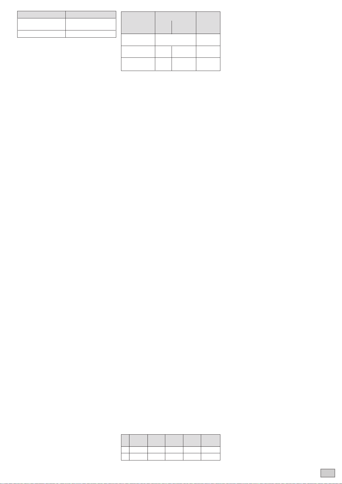
Lade- Baureihe Zellen-
verfahren GroE OGi, OPzS, span-
OCSM, nung
Energy Bloc
(OGi-LA Block)
IU-Kennlinie*)10 A bis 35 A bis 2,40 V
I-Kennlinie 6,5 A 5,0 A 2,60 V-
2,75 V
W-Kennlinie 9,0 A 7,0 A bei 2,40 V
4,5 A 3,5 A bei 2,65 V
Tabelle 3: Zulässige Ladeströme pro 100 Ah
Nennkapazität, *)= empfohlene Richtwerte
Tole- 4V- 6 V- 10 V- 12 V-
ranz Block Block Block Block
+ 0,14 V 0,17 V 0,22 V 0,24 V
- 0,07 V 0,09 V 0,11 V 0,12 V
Tabelle 4: Zulässige Abweichungen von der
durchschnittlichen Erhaltungsladespannung
für Blockbatterien
Jährlich sind zu messen und aufzuzeichnen:
annung aer eenBockbatterien
ektrottemeratur aer een
ektrotichte aer een
Jährliche Sichtkontrolle:
Der chrauberbinungen
Ungesicherte chrauberbinungen sin au
festen Sitz zu prüfen
Batterieausteung bw. unterbringung
Be un nttung es Batterieraumes
4. Prüfungen
rungen mssen gem DI 609611
durchgeführt werden. Sonder-Prüfanweisungen,
.B. nach DI VD 010 un DI 5012, sin
zusätzlich zu beachten.
Kapazitätstest
Um sicherusteen, ass ie Batterie or einem
Kapazitätstest (z.B. Abnahmetest in der Anlage)
o geaen ist, knnen ogene IUae
verfahren angewendet werden:
Möglichkeit 1: Ladespannung gem. Tabelle 2,
≥2 h.
Mgichkeit 2 2,0 V, ≥ 16 h ma. h, ge-
ogt on aen gem. unkt 2.3,
≥ h.
Der ergbare aestrom sote 10 bis 35
100 h ennkaaitt betragen.
5. Störungen
Werden Störungen an der Batterie oder der La-
deeinrichtung festgestellt, ist unverzüglich der
Kundendienst anzufordern. Messdaten gemäß
unkt 3 ereinachen ie ehersuche un ie
Störungsbeseitigung. Ein Servicevertrag, z.B.
mit Exide Technologies, erleichtert das rechtzei-
tige Erkennen von Fehlern.
6. Lagern und Außerbetriebnahme
Werden Zellen bzw. Batterien für längere Zeit
gelagert bzw. außer Betrieb genommen, so sind
diese vollgeladen in einem trockenen frostfreien
Raum unterzubringen.
Um chen u ermeien, knnen ogene
Ladebehandlungen gewählt werden:
1. Viertehriches achaen nach kt. 2..
Bei mittleren Raumtemperaturen von mehr
as er enntemeratur knnen krere
Abstände erforderlich sein.
2. rhatungsaen nach unkt 2.3.
7. Transport
Die Zellen/Blockbatterien müssen aufrecht
transportiert werden. Zellen/Blockbatterien, die
in keiner Weise Schäden aufweisen, werden
nach der Gefahrgutverordnung Straße (ADR)
bzw. Gefahrgutverordnung Eisenbahn (RID)
nicht als Gefahrgut befördert. Sie müssen gegen
urschuss, ut schen, Umaen oer Besch
digung gesichert sein. Blockbatterien können in
geeigneter Weise, gesichert auf Palette, gesta-
pelt werden (ADR bzw. RID, Sondervorschrift
59. aetten ren nicht gestaet weren. n
den Versandstücken dürfen sich von außen kei-
ne gefährlichen Spuren von Säure befinden.
Zellen/Blockbatterien, deren Gefäße undicht
bzw. beschädigt sind, müssen als Gefahrgut der
asse , Ur. 29, erackt un berert
werden.
Um as isiko irgeneines reignisses wie
Feuer etc. zu verhindern, müssen für Lufttransport
Batterien, die Teil irgendeines Gerätes sind, an
ihren Polen abgeklemmt und diese gegen
Kurzschluss geschützt werden.
8. Technische Daten
Die ennsannung, ie nah er een, ie
ennkaaitt 10 = C) und der Typ der Batte-
rie sind dem Typschild zu entnehmen. Andere
Kapazitäten (Cn) bei verschiedenen Entladeströ-
men (In) mit den entsprechenden Entladezeiten
(tn knnen anhan er abeen .1.1.1.5 ent-
nommen werden.
Baureihe Erhaltungs-
ladespannung/Zelle
GroE, OPzS-LA, Energy Bloc
OGi-LA Block/Zellen 2,23 V
OCSM-LA 2,25 V
Tabelle 2: Erhaltungsladespannung
GNB_Classic.indd 3 06.08.14 12:51

de
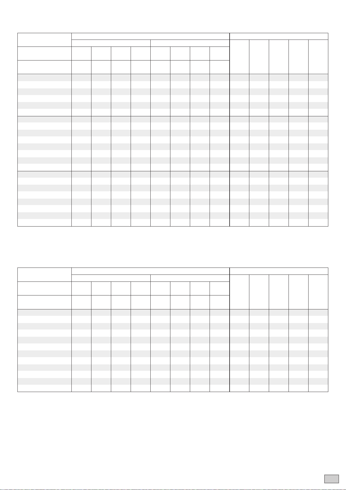
8.1 Abmessungen Gewichte und Kapazitäten bei verschiedenen Entladezeiten bis zur zulässigen Entladeschlussspannung
8.1.1 Ortsfeste Bleibatterie der Bauart OPzS (LA) DIN 40736 und Blockbatterie DIN 40737
mit os. aneratten un negatien Gitteratten, enneektrotichte 1,2 kg
Einzelzelle
2 OPzS 100 LA 128 113 102 71,8 12,8 22,6 34,3 71,8 105 208 395 13,7 5,2
3 OPzS 150 LA 168 147 134 91,7 16,8 29,5 44,9 91,7 105 208 395 15,2 5,0
4 OPzS 200 LA 214 188 171 118 21,4 37,6 57,1 118 105 208 395 16,6 4,6
5 OPzS 250 LA 265 231 210 145 26,5 46,3 70,0 145 126 208 395 20,0 5,8
6 OPzS 300 LA 316 274 247 171 31,6 54,9 82,6 171 147 208 395 23,3 6,9
5 OPzS 350 LA 380 325 291 211 38,0 65,0 97,3 211 126 208 511 26,7 8,1
6 OPzS 420 LA 455 389 348 246 45,5 77,8 116 246 147 208 511 31,0 9,3
7 OPzS 490 LA 530 453 408 280 53,0 90,6 136 280 168 208 511 35,4 10,8
6 OPzS 600 LA 680 560 501 364 68,0 112 167 364 147 208 686 43,9 13,0
7 OPzS 700 LA 750 615 552 401 75,0 123 184 401 147 208 686 47,2 12,8
8 OPzS 800 LA 910 760 678 502 91,0 152 226 502 212 193 686 59,9 17,1
9 OPzS 900 LA 980 820 729 541 98,0 164 243 541 212 193 686 63,4 16,8
10 OPzS 1000 LA 1140 945 843 620 114 189 281 620 212 235 686 73,2 21,7
12 OPzS 1200 LA 1370 1125 1008 733 137 225 336 733 212 277 686 86,4 26,1
12 OPzS 1500 LA 1700 1385 1239 853 170 277 413 853 212 277 836 108,0 33,7
14 OPzS 1750 LA 1800 1465 1311 904 180 293 437 904 212 277 836 114,0 32,7
16 OPzS 2000 LA 2250 1835 1641 1180 225 367 547 1180 215 400 812 151,0 50,0
18 OPzS 2250 LA 2450 1995 1785 1250 245 399 595 1250 215 400 812 158,0 48,0
20 OPzS 2500 LA 2800 2280 2040 1465 280 456 680 1465 215 490 812 184,0 60,0
22 OPzS 2750 LA 3000 2445 2187 1570 300 489 729 1570 215 490 812 191,0 58,0
24 OPzS 3000 LA 3350 2730 2442 1710 335 546 814 1710 215 580 812 217,0 71,0
1) Inklusive Verbinder, bei Verwendung von Spezialstopfen kann das Maß die angegebene Höhe übersteigen
Blockbatterie
Entladedaten Abmessungen und Gewichte
Kapazität [Ah] Entladestrom [A] Länge Breite Höhe
1) Gewicht Säure-
Entladezeit 10 5 3 1 10 5 3 1 max. max. max. mit gewicht
[h] Säure
Umin / Zelle 1,80 1,80 1,75 1,65 1,80 1,80 1,75 1,65 [mm] [mm] [mm] ca. [kg] ca. [kg]
[V]
12V 1 OPzS 50 LA 59,0 47,5 42,0 27,9 5,90 9,50 14,0 27,9 273 204 358 35 15
12V 2 OPzS 100 LA 101 85,5 77,7 55,5 10,1 17,1 25,9 55,5 273 204 358 45 14
12V 3 OPzS 150 LA 150 128 112 83,0 15,0 25,7 37,5 83,0 381 204 358 64 19
6V 4 OPzS 200 LA 203 174 150 113 20,3 34,9 50,0 113 273 204 358 41 13
6V 5 OPzS 250 LA 255 214 186 135 25,5 42,8 62,0 135 381 204 358 56 20
6V 6 OPzS 300 LA 303 255 223 165 30,3 51,0 74,5 165 381 204 358 63 20
GNB_Classic.indd 4 06.08.14 12:51
5
de
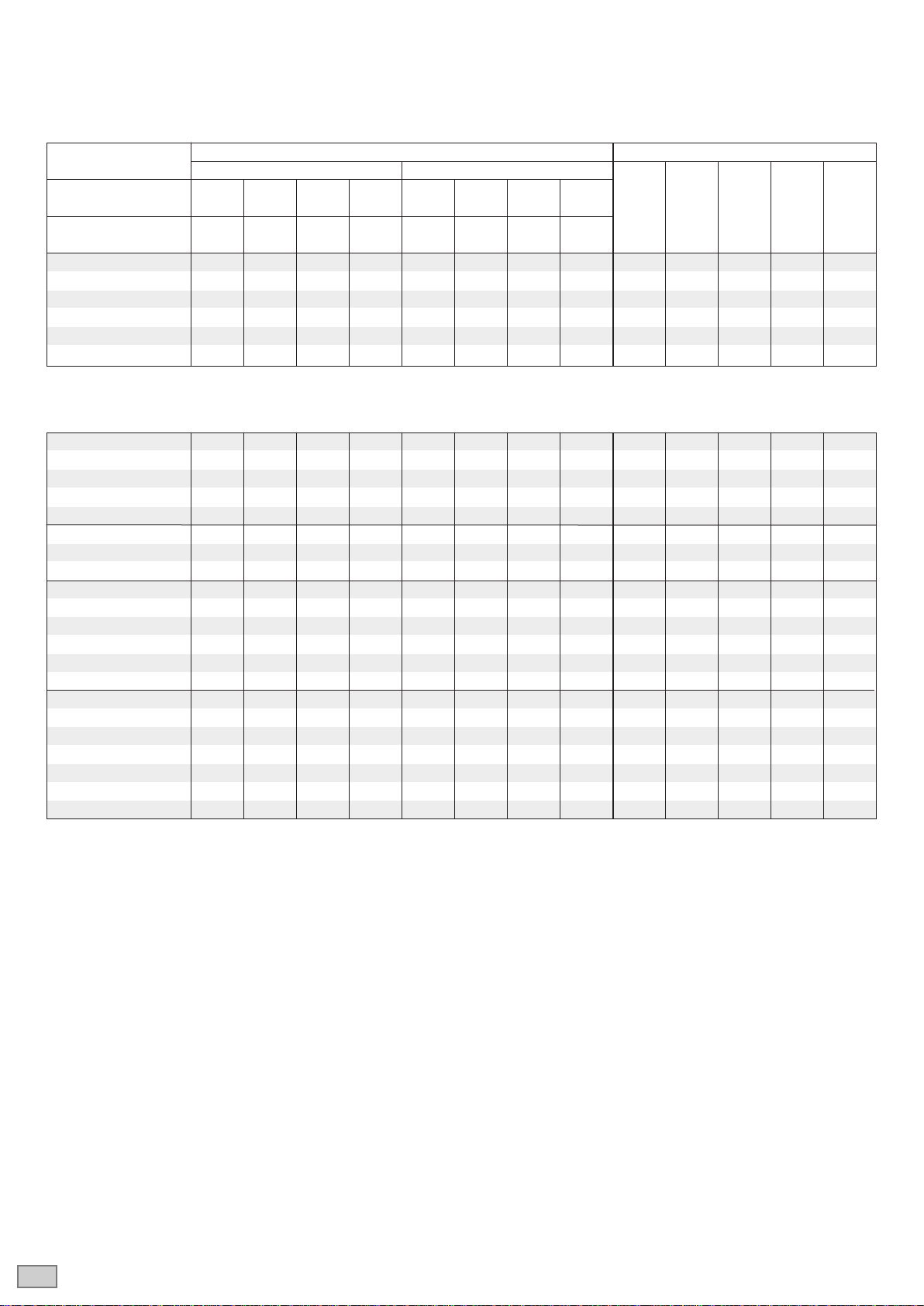
8.1.2 Ortsfeste Bleibatterie der Bauart OCSM (LA)
mit os. aneratten un negatien uerstreckmetaGitteratten, enneektrotichte 1,26 kg
Entladedaten Abmessungen und Gewichte
Kapazität [Ah] Entladestrom [A] Länge Breite Höhe
1) Gewicht Säure-
Entladezeit 10 5 3 1 10 5 3 1 max. max. max. mit gewicht
[h] Säure
Umin / Zelle 1,80 1,80 1,75 1,70 1,80 1,80 1,75 1,70 [mm] [mm] [mm] ca. [kg] ca. [kg]
[V]
2 OCSM 160 LA 170 144 129 91,2 17,0 28,8 43,2 91,2 126 208 522 19,8 8,4
3 OCSM 240 LA 255 216 194 137 25,5 43,2 64,7 137 126 208 522 22,6 8,2
4 OCSM 320 LA 340 288 259 182 34,0 57,5 86,3 182 126 208 522 25,1 7,9
5 OCSM 400 LA 425 360 324 228 42,5 71,9 108 228 126 208 522 28,3 8,2
6 OCSM 480 LA 510 432 388 274 51,0 86,3 129 274 147 208 522 33,1 9,7
7 OCSM 560 LA 595 503 453 319 59,5 101 151 319 168 208 522 37,9 11,1
5 OCSM 575 LA 591 514 467 338 59,1 103 156 338 147 208 698 41,8 13,4
6 OCSM 690 LA 709 616 560 406 70,9 123 187 406 147 208 698 45,4 13,3
7 OCSM 805 LA 827 719 653 474 82,7 144 218 474 215 193 698 58,3 17,3
8 OCSM 920 LA 946 822 747 541 94,6 164 249 541 215 193 698 61,9 17,7
9 OCSM 1035 LA 1064 925 840 609 106 185 280 609 215 235 698 71,6 21,6
10 OCSM 1150 LA 1182 1027 933 676 118 205 311 676 215 235 698 75,7 21,8
11 OCSM 1265 LA 1300 1130 1027 744 130 226 342 744 215 277 698 86,3 26,5
12 OCSM 1380 LA 1418 1233 1120 812 142 247 373 812 215 277 698 88,9 26,4
11 OCSM 1595 LA 1743 1468 1289 891 174 294 430 891 215 277 848 106 33,3
12 OCSM 1740 LA 1902 1602 1406 972 190 320 469 972 215 277 848 110 32,8
14 OCSM 2030 LA 2219 1869 1640 1134 222 374 547 1134 215 400 824 143 47,8
16 OCSM 2320 LA 2536 2136 1874 1296 254 427 625 1296 215 400 824 152 46,9
18 OCSM 2610 LA 2853 2403 2108 1458 285 481 703 1458 215 490 824 178 57,9
20 OCSM 2900 LA 3170 2670 2343 1620 317 534 781 1620 215 490 824 186 55,6
22 OCSM 3190 LA 3487 2937 2577 1782 349 587 859 1782 215 580 824 224 68,0
24 OCSM 3480 LA 3804 3204 2811 1944 380 641 937 1944 215 580 824 222 67,1
1) Bei Verwendung von Spezialstopfen kann das Maß die angegebene Höhe übersteigen
8.1.3 Ortsfeste Bleibatterie Energy Bloc (OGi-Blockbatterie)
mit ositien un negatien Gitteratten, enneektrotichte 1,2 kg
Entladedaten Abmessungen und Gewichte
Kapazität [Ah] Entladestrom [A] Länge Breite Höhe
1) Gewicht Säure-
Entladezeit 10 5 3 1 10 5 3 1 max. max. max. mit gewicht
[h] Säure
Umin / Zelle 1,80 1,80 1,80 1,75 1,80 1,80 1,80 1,75 [mm] [mm] [mm] ca. [kg] ca. [kg]
[V]
EB 1230 30,0 26,5 23,1 17,3 3,00 5,30 7,70 17,3 273 204 358 28,7 12,7
EB 1260 61,0 52,5 46,2 34,7 6,10 10,5 15,4 34,7 273 204 358 33,9 11,8
EB 1285 85,0 75,5 66,6 50,3 8,50 15,1 22,2 50,3 273 204 358 39,1 10,7
EB 12110 105 96,0 84,9 64,7 10,5 19,2 28,3 64,7 273 204 358 44,2 10,6
EB 12145 141 126 111 83,8 14,1 25,2 37,0 83,8 381 204 358 57,8 15,2
EB 12160 158 144 127 97,1 15,8 28,8 42,5 97,1 381 204 358 64,2 15,1
EB 6215 211 184 162 121 21,1 36,9 54,0 121 273 204 358 41,2 11,6
EB 6230 226 201 177 134 22,6 40,3 59,2 134 273 204 358 43,4 11,1
EB 6240 237 216 191 145 23,7 43,2 63,7 145 273 204 358 46,0 11,0
EB 6310 302 263 231 173 30,2 52,7 77,2 173 381 204 358 56,9 16,80
EB 6335 332 290 255 190 33,2 58,0 85,0 190 381 204 358 59,6 16,40
EB 6350 339 302 266 201 33,9 60,5 88,8 201 381 204 358 62,3 15,80
1) Inklusive Verbinder, bei Verwendung von Spezialstopfen kann das Maß die angegebene Höhe übersteigen
GNB_Classic.indd 5 06.08.14 12:51

6
de
8.1.4 Ortsfeste Bleibatterie der Bauart GroE gem. DIN 40 738
mit os. Grooberchenatten un negatien Gitteratten, enneektrotichte 1,22 kg
Entladedaten Abmessungen und Gewichte
Kapazität [Ah] Entladestrom [A] Länge Breite Höhe
1) Gewicht Säure-
Entladezeit 10 5 3 1 10 5 3 1 max. max. max. mit gewicht
[h] Säure
Umin / Zelle 1,80 1,80 1,775 1,75 1,80 1,80 1,775 1,75 [mm] [mm] [mm] ca. [kg] ca. [kg]
[V]
3 GroE 75 75 76,5 68,4 50,7 7,50 15,3 22,8 50,7 182 153 411 17,5 6,6
4 GroE 100 100 102 91,2 67,6 10,0 20,4 30,4 67,6 182 153 411 19,7 6,4
5 GroE 125 125 127 114 84,5 12,5 25,5 38,0 84,5 182 153 411 21,9 6,2
6 GroE 150 150 153 136 101 15,0 30,6 45,6 101 182 153 411 24,1 6,0
7 GroE 175 175 178 159 118 17,5 35,7 53,2 118 182 153 411 26,3 5,8
8 GroE 200 200 204 182 135 20,0 40,8 60,8 135 182 228 411 33,2 9,4
9 GroE 225 225 229 205 152 22,5 45,9 68,4 152 182 228 411 35,4 9,2
10 GroE 250 250 255 228 169 25,0 51,0 76,0 169 182 228 411 37,6 9,0
11 GroE 275 275 280 250 185 27,5 56,1 83,6 185 182 228 411 39,8 8,8
12 GroE 300 300 306 273 202 30,0 61,2 91,2 202 182 228 411 42,0 8,6
13 GroE 325 325 331 296 219 32,5 66,3 98,8 219 182 338 411 52,5 14,1
14 GroE 350 350 357 318 236 35,0 71,4 106 236 182 338 411 54,7 13,8
15 GroE 375 375 382 342 253 37,5 76,5 114 253 182 338 411 56,9 13,6
16 GroE 400 400 408 363 270 40,0 81,6 121 270 182 338 411 59,1 13,3
17 GroE 425 425 433 387 287 42,5 86,7 129 287 182 338 411 61,3 13,0
18 GroE 450 450 459 408 304 45,0 91,8 136 304 182 338 411 63,5 12,7
5 GroE 500 500 462 438 307 50,0 92,5 146 307 328 268 590 95 34
6 GroE 600 600 555 525 369 60,0 111 175 369 328 268 590 104 33
7 GroE 700 700 645 612 430 70,0 129 204 430 328 268 590 113 32
8 GroE 800 800 740 699 492 80,0 148 233 492 328 268 590 122 31
9 GroE 900 900 830 786 553 90,0 166 262 553 328 268 590 131 30
10 GroE 1000 1000 925 876 615 100 185 292 615 328 268 590 140 29
11 GroE 1100 1100 1015 963 676 110 203 321 676 328 268 590 149 28
12 GroE 1200 1200 1110 1050 738 120 222 350 738 328 348 590 170 39
13 GroE 1300 1300 1200 1137 799 130 240 379 799 328 348 590 179 38
14 GroE 1400 1400 1295 1224 861 140 259 408 861 328 348 590 188 37
15 GroE 1500 1500 1385 1314 922 150 277 438 922 328 348 590 197 36
16 GroE 1600 1600 1480 1401 984 160 296 467 984 328 438 590 222 49
17 GroE 1700 1700 1570 1488 1045 170 314 496 1045 328 438 590 231 48
18 GroE 1800 1800 1665 1575 1107 180 333 525 1107 328 438 590 240 47
19 GroE 1900 1900 1755 1662 1168 190 351 554 1168 328 438 590 249 46
20 GroE 2000 2000 1850 1752 1230 200 370 584 1230 328 438 590 258 45
21 GroE 2100 2100 1940 1839 1291 210 388 613 1291 328 528 590 285 58
22 GroE 2200 2200 2035 1926 1353 220 407 642 1353 328 528 590 294 57
23 GroE 2300 2300 2125 2013 1414 230 425 671 1414 328 528 590 303 56
24 GroE 2400 2400 2220 2100 1476 240 444 700 1476 328 528 590 312 55
25 GroE 2500 2500 2310 2190 1537 250 462 730 1537 328 573 590 325 60
26 GroE 2600 2600 2405 2277 1599 260 481 759 1599 328 573 590 334 59
1) Inklusive Verbinder, bei Verwendung von Spezialstopfen kann das Maß die angegebene Höhe übersteigen
GNB_Classic.indd 6 06.08.14 12:51

de
8.1.5 Ortsfeste Bleibatterie der Bauart OGi (LA)
mit ositien un negatien Gitteratten, enneektrotichte 1,26 kg
* enneektrotichte 1,2 kg
2 OGi 50 LA* 50 45,0 36,6 26 5,0 9,0 12,2 26 69 160 351 6,30 2,30
3 OGi 75 LA* 75 67,5 54,6 39 7,5 13,5 18,2 39 69 160 351 7,00 2,10
4 OGi 100 LA* 100 90,0 71,4 51 10,0 18,0 23,8 51 125 160 384 11,5 4,90
6 OGi 150 LA* 150 135,0 107,4 75 15,0 27,0 35,8 75 125 160 384 13,3 4,60
8 OGi 200 LA* 200 177,5 143,1 98 20,0 35,5 47,7 98 155 160 384 16,8 5,80
10 OGi 250 LA* 250 222,5 178,8 120 25,0 44,5 59,6 120 194 160 384 20,9 7,30
4 OGi 260 LA 260 224,5 186,3 129 26,0 44,9 62,1 129 124 206 511 20,8 8,20
5 OGi 325 LA 325 280,0 233,1 161 32,5 56,0 77,7 161 124 206 511 22,9 7,90
6 OGi 370 LA 370 312,5 268,2 192 37,0 62,5 89,4 192 124 206 511 24,7 7,50
7 OGi 410 LA 410 347,5 303,0 224 41,0 69,5 101,0 224 124 206 511 26,6 7,30
8 OGi 440 LA 440 382,5 339,0 255 44,0 76,5 113,0 255 124 206 511 28,5 7,10
9 OGi 470 LA 470 417,5 375,0 287 47,0 83,5 125,0 287 124 206 511 30,6 6,90
10 OGi 530 LA 530 465,0 420,0 316 53,0 93,0 140,0 316 145 206 511 34,0 8,10
11 OGi 580 LA 580 515,0 465,0 346 58,0 103,0 155,0 346 166 206 511 38,3 9,80
12 OGi 620 LA 620 562,5 513,0 375 62,0 112,5 171,0 375 166 206 511 40,0 9,40
12 OGi 730 LA 730 585,0 579,0 383 73,0 117,0 193,0 383 210 254 511 50,3 17,5
14 OGi 800 LA 800 715,0 636,0 482 80,0 143,0 212,0 482 210 254 511 52,6 15,9
16 OGi 880 LA 880 770,0 687,0 520 88,0 154,0 229,0 520 210 254 511 56,6 15,5
19 OGi 1000 LA 1000 857,5 762,0 578 100,0 171,5 254,0 578 210 254 511 62,5 14,9
16 OGi 1260 LA 1260 1117,5 1002,0 718 126,0 223,5 334,0 718 210 233 688 78,2 18,3
18 OGi 1340 LA 1340 1187,5 1065,0 763 134,0 237,5 355,0 763 210 233 688 85,2 19,7
20 OGi 1520 LA 1520 1347,5 1209,0 869 152,0 269,5 403,0 869 210 275 688 95,2 22,3
22 OGi 1600 LA 1600 1420,0 1272,0 915 160,0 284,0 424,0 915 210 275 688 103 23,3
1) Bei Verwendung von Spezialstopfen kann das Maß die angegebene Höhe übersteigen
Einzelzelle
Entladedaten Abmessungen und Gewichte
Kapazität [Ah] Entladestrom [A] Länge Breite Höhe
1) Gewicht Säure-
Entladezeit 10 5 3 1 10 5 3 1 max. max. max. mit gewicht
[h] Säure
Umin / Zelle 1,80 1,77 1,75 1,67 1,80 1,77 1,75 1,67 [mm] [mm] [mm] ca. [kg] ca. [kg]
[V]
GNB_Classic.indd 7 06.08.14 12:51

en
Observe these Instructions and keep them located near the battery for future
reference!
Work on the battery should only be carried out by qualified personnel.
Do not smoke!
Do not use any naked flame or other sources of ignition.
Risk of explosion and fire!
While working on batteries wear protective goggles and clothing!
Observe the accident prevention rules as well as EN 50272-2,
EN 50110-1!
Any acid splashes on the skin or in the eyes must be rinsed with plenty of
clean water immediately. Then seek medical assistance.
Spillages on clothing should be rinsed out with water!
Explosion and fire hazard, avoid short circuits.
Avoid electrostatic charges and discharges/sparks!
Blocks/cells are very heavy! Make sure they are installed securely! Only use
suitable means of transport!
Block/cell containers are sensitive to mechanical damage.
Handle with care!
Do not lift or pull up blocks/cells on the poles.
Caution! Dangerous voltage.
Metal parts of the battery are always alive, therefore do not place
items or tools on the battery!
Electolyte is strongly corrosive!
Non-compliance with operating instructions and installations or repairs made with other than
original accessories and spare parts or with accessories and spare parts not recommended
by the battery manufacturer or repairs made without authorization and use of additives for
the electrolytes (alleged enhancing agents) render the warranty void.
Spent batteries have to be collected and recycled separately from normal household
wastes (EWC 160601). The handling of spent batteries is described in the EU Battery
Directive (2006/66/EC) and their national transitions (UK: HS Regulation 1994 No. 232,
Ireland: Statory Instrument No. 73/2000). Contact your supplier to agree upon the
recollection and recycling of your spent batteries or contact a local and authorized
Waste Management Company.
Pb
1. Start Up
The commissioning should take place as soon
as possible after receipt of the battery. If this is
not possible, advises acc. to item 6. shall be
taken into account. Check all cells/blocks for
mechanical damage, correct polarity and firmly
seated connectors. The following torques apply
to the cell types:
Put covers on the terminals if necessary. Check
the electrolyte level in all cells and if necessary
top up to maximum level with purified water as
acc. to DI 3530 art . onnect the batter
with the correct polarity to the charger (pos. pole
to pos. terminal). The charger must not be
switched on during this process, and the load
must not be connected. Switch on charger and
start charging following item 2.2.
The insulation resistance measured at the dis-
connected loads and charger should be ≥100 Ω
per volt nominal voltage.
2. Operation
For the installation and operation of stationary
batteries 50 222 is manator.
The battery must be installed in a way which
prevents ambiance-dependent temperature
differences of > 10 K arising. The spacing
between the cells or blocks should be 10 mm
an at east 5 mm in rack mounting.
2.1 Discharge
Discharge must not be continued below the volt-
age recommended for the discharge time.
Deeper discharges must not be carried out
unless specifically agreed with the manufacturer.
Recharge immediately following complete or
partial discharge.
2.2 Charging
All charging characteristics with their specific
data, described in
DI 13 IUcharacteristic, Iconst. 2,
Uconst. 1
DI 1 characteristic, 0.05 Vc
DI 16 Icharacteristic, Iconst. 2
may be used. According to the charging equip-
ment, specification and characteristics alternat-
ing currents flow through the battery superim-
posing onto the direct current during charge
operation.
Alternating currents and the reaction of the loads
may lead to an additional temperature increase
of the battery, and strain the electrodes with
ossibe amage see oint 2.5, which can
shorten the battery life. Depending on the instal-
ation, charging acc. to 50222 ma be
carried out in following operations:
a) Standby Parallel Operation
Here the load, battery and battery charger are
continuously in parallel. Thereby, the charge
voltage is the operation voltage and at the same
time the battery installation voltage.
With the standby parallel operation, the battery
charger is capable, at any time, of supplying the
maximum load current and the battery charging
current. The battery only supplies current when
the battery charger fails. The float charge voltage
measured at the end terminals of the battery
should be set at the values in table 2. To reduce
the charging time, a boost-charging stage can be
aie in which the charge otage o 2.33 V
2.0 V number o ces can be auste stan-
by parallel operation with boost recharging
stage). Automatic changeover to float charging
voltage acc. to table 2.
With buffer operation, the battery charger is not
able to supply the maximum load current at all
times. The load current intermittently exceeds
the nominal current of the battery charger.
During this period the battery supplies power.
This results in the battery not being fully charged
at all times. Therefore, depending on the load
the charge otage must be set at 2.25 V 2.30
V x number of cells. This has to be carried out in
accordance with the manufacturers instructions.
Nominal data
omina otage U: 2.0 V x number of cells
omina caacit = C10 : 10 h discharge (see type plate on cells and technical data in these instructions)
omina ischarge current I= I10 : C/ 10 h
ina ischarge otage Uf: see technical data in these instructions
omina temerature t: 20° C
Batter te umber o cesbocks
ssemb b GB orer no. ate
Commissioned by: date:
Safety signs attached by: date:
GroE, OCSM-LA, Energy Bloc OGi-LA Cells
OPzS-LA Cells OPzS Block ≤250 Ah ≥260 Ah
20 Nm 12 Nm 8 Nm 20 Nm
Table 1: Torques with a tolerance of ± 1 Nm
Classic Range: GroE, OPzS-LA, OCSM-LA, OGi-LA, Energy Bloc
Operating Instructions
for stationary lead acid batteries
GNB_Classic.indd 8 06.08.14 12:51

9
en
Tolerance 4 V- 6 V- 10 V- 12 V-
Block Block Block Block
+ 0.14 V 0.17 V 0.22 V 0.24 V
- 0.07 V 0.09 V 0.11 V 0.12 V
Table 4: Permissible deviation from the average
charge retention for block batteries
b) Switch mode operation
When charging, the battery is separated from the
load. Towards the end of the charging process
the charge otage o the batter is 2.6 V 2.5
V times the number of cells. The charging pro-
cess must be monitore see oints 2., 2.5 an
2.6 On reaching a u charge state, the
charging process must be stopped or switched
to oat charge as in oint 2.3.
c) Battery Operation
(charge-/discharge operation)
The load is supplied by the battery only, whereby
the charge voltage of the battery towards the
en o the charging rocess can be 2.6 V 2.5 V
times the number of cells. The charging process
must be monitore see oints 2., 2.5 an 2.6
On reaching a fully charged state, the charging
process must be switched off. The battery can
be switched to the load as required.
2.3 Maintaining full charge
(float charging)
The devices used must comply with the stipula-
tions uner DI 13. he are to be set so that
the average cell voltage is see table 2 and the
electrolyte density should not decrease over a
lengthy period.
2.4 Equalizing charge
Because it is possible to exceed the permitted
load voltages, appropriate measures must be
taken, e.g. switch off the load.
Equalizing charges are required after deep dis-
charges and/or inadequate charges. They can
be carried out as follows:
at constant otage o ma. 2. Vc u to 2
hours
with I or characteristic as in oint 2.6.
The electrolyte temperature must never exceed
55 . I it oes, sto charging or reert to oat
charge to allow the temperature to drop.
The end of the equalizing charge is reached
when the electrolyte density and the cell volt-
ages no longer increase over a period of 2 hours.
(2 h -criterion only applies to I- and W-charac-
teristics).
2.5 Alternating currents
hen recharging u to 2. Vc uner oeration
modes 2.2 the value of the alternating current is
occasionally permitted to reach 10 A (RMS) per
100 Ah nominal capacity.
In a fully charged state during float charge or
standby parallel operation the actual value of the
aternating current must not ecee 5 M
per 100 Ah nominal capacity.
2.6 Charging currents
The charging currents are not limited during
standby parallel operation or buffer operation
IUcharge characteristic with otages u to
2. Vc reerence aues 10 u to 35 er
100 Ah nominal capacity).
Charging by I- or W-characteristic results in volt-
ages higher than 2. Vc an thereore increas
ed decomposition of water. The charging cur-
rents per 100 Ah nominal capacity shown in the
following table must not be exceeded.
2.7 Temperature
The recommended operating temperature range
or ea aci batteries is 10 to 30 . tech
nical data apply to the nominal temperature
20° C.
he iea oerating temerature is 20 5 .
Higher temperatures will seriously reduce ser-
vice life. Lower temperatures reduce the avail-
able capacity. The absolute maximum tempera-
ture is 55 .
2.8 Temperature-related charge voltage
A temperature related adjustment of the charge
voltage within the operating temperature of 10° C
to 30 is not necessar. I the oerating tem-
perature is constantly outside this range, the
charge voltage has to be adjusted.
he temerature correction actor is 0.00 Vc
er . hereb 2. Vc must not be eceee
an the otage must not come beow 2.15 Vc
OM 2.1 Vc.
2.9 Electrolyte
The electrolyte density is diluted sulphuric acid.
he nomina eectrote ensit 0.01 kg acc.
to technical data) is based on 20 °C when fully
charged and with the maximum electrolyte level.
Higher temperatures reduce electrolyte density,
lower temperatures increase electrolyte density.
he aroriate correction actor is 0.000 kg
per K.
ame eectrote ensit o 1.23 kg at 35
corresons to a ensit o 1.2 kg at 20 or
an eectrote ensit o 1.25 kg at 5 corre
sons to a ensit o 1.2 kg at 20 .
3. Battery maintenance and control
The electrolyte level must be checked regularly.
If it drops to the lower electrolyte level mark,
purified water must be added in accordance with
DI 3530 art maimum conuctiit
30 cm. ee the batter cean an r to
avoid leakage currents. Plastic parts of the bat-
tery, especially containers, must be cleaned with
pure water without additives.
At least every 6 months measure and record:
Batter otage
Votage o some cesbock batteries
ectrote temerature o some ces
Batterroom temerature
ectrote ensit o some ces
If the cell voltages deviate by more than + 0.1 V
or 0.05 V or bocks see tabe rom the aer-
age charge retention voltage (see table 2), and/
or if the electrolyte density of the cells of a bat-
tery string deviates from the average-value more
than - 0.01/+ 0.02 kg/l (reference values), call
customer service.
Annual measurement and recording:
Votage o a cesbock batteries
ectrote temerature o a ces
ectrote ensit o a ces
Annual visual check:
crew connections
crew connections without ocking eices
have to be checked for tightness
Batter instaation an arrangement
Ventiation
4. Tests
Tests have to be carried out according to
I 609611. ecia instructions ike DI VD
010 an DI 5012 hae to be obsere.
Capacity test, for instance, acceptance test
on site: In order to make sure the battery is fully
charge the oowing IUcharge methos must
be applied: Option 1: float charge (see table 2),
≥ 2 hours. Otion 2 2.0 Vc, ≥16 hours (max.
hours oowe b oat charge see item 2.3,
≥ hours. he current aaiabe to the batter
must be between 10 100 h an 35 100 h
of the C10-capacity.
5. Faults
Call the services agents immediately if faults in
the battery or charging unit are found. Recorded
ata as escribe in oint 3. simi the troube-
shooting and fault clearance. A service contract
for example with Exide Technologies facilitates
detecting faults in time.
6. Storage and taking out of operation
To store or decommission cells/blocks for a
longer period of time they should be fully charged
and stored in a dry and cold but frost-free room,
away from direct sunlight. To avoid damage the
following charging methods can be chosen:
To prevent damage, choose the following charg-
ing methods:
1. Refreshing charges every three months as
escribe uner oint 2..
At average ambient temperatures of more
than the nominal temperature shorter inter-
vals can be necessary.
2. oat charging as uner oint 2.3.
7. Transport
Cells/block batteries must be transported in an
upright position. Cells/block batteries without
any visible damage are not defined as hazardous
goods under the regulations for transport of
hazardous goods by road (ADR) or by railway
(RID). They must be protected against short cir-
cuits, slipping, upsetting or damaging. Block
batteries may be suitably stacked and secured
on aets D an ID, secia roision 59.
It is rohibite to stack aets. o angerous
traces of acid may be found on the exteriors of
the packing units. Cells/block batteries whose
cases leak or are damaged must be packed and
transorte as cass haarous goos uner
U no. 29.
In case of air transport, batteries which are part
of any equipment must be disconnected at their
terminals, and the terminals must be protected
against short-circuits. This is in order to avoid
the risk of any incidents like fire etc.
8. Technical data
The nominal voltage, the number of cells, the
nominal capacity (C10 = C) and the battery type
are described on the type plate. Other capacities
(Cn) at different discharge currents (In) with the
corresponding discharge times (tn) see table
.1.1 .1.5.
Range Float charge voltage per cell
GroE, OPzS-LA,
Energy Bloc, 2.23 V
OGi-LA block / cell
OCSM-LA 2.25 V
Table 2: Float charge voltage
Charging Range Cell
procedure GroE OGi-LA,
OPzS-LA, voltage
OCSM-LA,
Energy Bloc
(OGi-LA Block)
IU- 10 A to 35 A up to
characteristic*) 2.40 V
I- 6.5 A 5.0 A 2.60 V-
characteristic 2.75 V
W- 9.0 A 7.0 A at 2.40 V
characteristic 4.5 A 3.5 A at 2.65 V
Table 3: Permissible charging currents per 100 Ah
nominal capacity, *) = recommended values
GNB_Classic.indd 9 06.08.14 12:51
10
en
8.1 Measurements, weights and capacities at different discharge times and final discharge voltage
8.1.1 Stationary lead acid batteries type OPzS-LA acc. to DIN 40736 and DIN 40737
with ositie tubuar ates an negatie gri ates, omina eectrote ensit 1.2 kg
Blocks
Discharge data Measurements and weights
Capacity [Ah] discharge current [A] Length Width Height
1) Weight Weight
Discharge time 10 5 3 1 10 5 3 1 max. max. max. with acid
[h] acid
Final discharge voltage 1.80 1.80 1.75 1.65 1.80 1.80 1.75 1.65 approx. approx.
[Vpc] [mm] [mm] [mm] [kg] [kg]
12V 1 OPzS 50 LA 59.0 47.5 42.0 27.9 5.90 9.50 14.0 27.9 273 204 358 35 15
12V 2 OPzS 100 LA 101 85.5 77.7 55.5 10.1 17.1 25.9 55.5 273 204 358 45 14
12V 3 OPzS 150 LA 150 128 112 83.0 15.0 25.7 37.5 83.0 381 204 358 64 19
6V 4 OPzS 200 LA 203 174 150 113 20.3 34.9 50.0 113 273 204 358 41 13
6V 5 OPzS 250 LA 255 214 186 135 25.5 42.8 62.0 135 381 204 358 56 20
6V 6 OPzS 300 LA 303 255 223 165 30.3 51.0 74.5 165 381 204 358 63 20
Cells
2 OPzS 100 LA 128 113 102 71.8 12.8 22.6 34.3 71.8 105 208 395 13.7 5.2
3 OPzS 150 LA 168 147 134 91.7 16.8 29.5 44.9 91.7 105 208 395 15.2 5.0
4 OPzS 200 LA 214 188 171 118 21.4 37.6 57.1 118 105 208 395 16.6 4.6
5 OPzS 250 LA 265 231 210 145 26.5 46.3 70.0 145 126 208 395 20.0 5.8
6 OPzS 300 LA 316 274 247 171 31.6 54.9 82.6 171 147 208 395 23.3 6.9
5 OPzS 350 LA 380 325 291 211 38.0 65.0 97.3 211 126 208 511 26.7 8.1
6 OPzS 420 LA 455 389 348 246 45.5 77.8 116 246 147 208 511 31.0 9.3
7 OPzS 490 LA 530 453 408 280 53.0 90.6 136 280 168 208 511 35.4 10.8
6 OPzS 600 LA 680 560 501 364 68.0 112 167 364 147 208 686 43.9 13.0
7 OPzS 700 LA 750 615 552 401 75.0 123 184 401 147 208 686 47.2 12.8
8 OPzS 800 LA 910 760 678 502 91.0 152 226 502 212 193 686 59.9 17.1
9 OPzS 900 LA 980 820 729 541 98.0 164 243 541 212 193 686 63.4 16.8
10 OPzS 1000 LA 1140 945 843 620 114 189 281 620 212 235 686 73.2 21.7
12 OPzS 1200 LA 1370 1125 1008 733 137 225 336 733 212 277 686 86.4 26.1
12 OPzS 1500 LA 1700 1385 1239 853 170 277 413 853 212 277 836 108.0 33.7
14 OPzS 1750 LA 1800 1465 1311 904 180 293 437 904 212 277 836 114.0 32.7
16 OPzS 2000 LA 2250 1835 1641 1180 225 367 547 1180 215 400 812 151.0 50.0
18 OPzS 2250 LA 2450 1995 1785 1250 245 399 595 1250 215 400 812 158.0 48.0
20 OPzS 2500 LA 2800 2280 2040 1465 280 456 680 1465 215 490 812 184.0 60.0
22 OPzS 2750 LA 3000 2445 2187 1570 300 489 729 1570 215 490 812 191.0 58.0
24 OPzS 3000 LA 3350 2730 2442 1710 335 546 814 1710 215 580 812 217.0 71.0
1) Includes installed connector, the above mentioned height can differ depending on the used vent(s)
GNB_Classic.indd 10 06.08.14 12:51

11
en
8.1.2 Stationary lead acid cells type OCSM-LA
with ositie tubuar ates an negatie coer stretch meta gri ates, omina eectrote ensit 1.26 kg
Discharge data Measurements and weights
Capacity [Ah] discharge current [A] Length Width Height
1) Weight Weight
Discharge time 10 5 3 1 10 5 3 1 max. max. max. with acid
[h] acid
Final discharge voltage 1.80 1.80 1.75 1.70 1.80 1.80 1.75 1.70 approx. approx.
[Vpc] [mm] [mm] [mm] [kg] [kg]
2 OCSM 160 LA 170 144 129 91.2 17.0 28.8 43.2 91.2 126 208 522 19.8 8.4
3 OCSM 240 LA 255 216 194 137 25.5 43.2 64.7 137 126 208 522 22.6 8.2
4 OCSM 320 LA 340 288 259 182 34.0 57.5 86.3 182 126 208 522 25.1 7.9
5 OCSM 400 LA 425 360 324 228 42.5 71.9 108 228 126 208 522 28.3 8.2
6 OCSM 480 LA 510 432 388 274 51.0 86.3 129 274 147 208 522 33.1 9.7
7 OCSM 560 LA 595 503 453 319 59.5 101 151 319 168 208 522 37.9 11.1
5 OCSM 575 LA 591 514 467 338 59.1 103 156 338 147 208 698 41.8 13.4
6 OCSM 690 LA 709 616 560 406 70.9 123 187 406 147 208 698 45.4 13.3
7 OCSM 805 LA 827 719 653 474 82.7 144 218 474 215 193 698 58.3 17.3
8 OCSM 920 LA 946 822 747 541 94.6 164 249 541 215 193 698 61.9 17.7
9 OCSM 1035 LA 1064 925 840 609 106 185 280 609 215 235 698 71.6 21.6
10 OCSM 1150 LA 1182 1027 933 676 118 205 311 676 215 235 698 75.7 21.8
11 OCSM 1265 LA 1300 1130 1027 744 130 226 342 744 215 277 698 86.3 26.5
12 OCSM 1380 LA 1418 1233 1120 812 142 247 373 812 215 277 698 88.9 26.4
11 OCSM 1595 LA 1743 1468 1289 891 174 294 430 891 215 277 848 106 33.3
12 OCSM 1740 LA 1902 1602 1406 972 190 320 469 972 215 277 848 110 32.8
14 OCSM 2030 LA 2219 1869 1640 1134 222 374 547 1134 215 400 824 143 47.8
16 OCSM 2320 LA 2536 2136 1874 1296 254 427 625 1296 215 400 824 152 46.9
18 OCSM 2610 LA 2853 2403 2108 1458 285 481 703 1458 215 490 824 178 57.9
20 OCSM 2900 LA 3170 2670 2343 1620 317 534 781 1620 215 490 824 186 55.6
22 OCSM 3190 LA 3487 2937 2577 1782 349 587 859 1782 215 580 824 224 68.0
24 OCSM 3480 LA 3804 3204 2811 1944 380 641 937 1944 215 580 824 222 67.1
1) The above mentioned height can differ depending on the used vents
8.1.3 Stationary lead acid block batteries Energy Bloc (OGi-Block battery)
with ositie an negatie gri ates, omina eectrote ensit 1,2 kg
Discharge data Measurements and weights
Capacity [Ah] discharge current [A] Length Width Height
1) Weight Weight
Discharge time 10 5 3 1 10 5 3 1 max. max. max. including of acid
[h] acid
Final discharge voltage 1.80 1.80 1.80 1.75 1.80 1.80 1.80 1.75
approx. approx.
[Vpc] [mm] [mm] [mm] ca. [kg] ca. [kg]
EB 1230 30.0 26.5 23.1 17.3 3.00 5.30 7.70 17.3 273 204 358 28.7 12.7
EB 1260 61.0 52.5 46.2 34.7 6.10 10.5 15.4 34.7 273 204 358 33.9 11.8
EB 1285 85.0 75.5 66.6 50.3 8.50 15.1 22.2 50.3 273 204 358 39.1 10.7
EB 12110 105 96.0 84.9 64.7 10.5 19.2 28.3 64.7 273 204 358 44.2 10.6
EB 12145 141 126 111 83.8 14.1 25.2 37.0 83.8 381 204 358 57.8 15.2
EB 12160 158 144 127 97.1 15.8 28.8 42.5 97.1 381 204 358 64.2 15.1
EB 6215 211 184 162 121 21.1 36.9 54.0 121 273 204 358 41.2 11.6
EB 6230 226 201 177 134 22.6 40.3 59.2 134 273 204 358 43.4 11.1
EB 6240 237 216 191 145 23.7 43.2 63.7 145 273 204 358 46.0 11.0
EB 6310 302 263 231 173 30.2 52.7 77.2 173 381 204 358 56.9 16.80
EB 6335 332 290 255 190 33.2 58.0 85.0 190 381 204 358 59.6 16.40
EB 6350 339 302 266 201 33.9 60.5 88.,8 201 381 204 358 62.3 15.80
1) Includes installed connector, the above mentioned height can differ depending on the used vent(s)
GNB_Classic.indd 11 06.08.14 12:51

12
en
8.1.4 Stationary lead acid batteries type GroE acc. to DIN 40 738
with ositie ates an negatie gri ates, omina eectrote ensit 1.22 kg
Discharge data Measurements and weights
Capacity [Ah] discharge current [A] Length Width Height
1) Weight Weight
Discharge time 10 5 3 1 10 5 3 1 max. max. max. with acid
[h] acid
Final discharge voltage 1.80 1.80 1.775 1.75 1.80 1.80 1.775 1.75 approx. approx.
[Vpc] [mm] [mm] [mm] [kg] [kg]
3 GroE 75 75 76.5 68.4 50.7 7.50 15.3 22.8 50.7 182 153 411 17.5 6.6
4 GroE 100 100 102 91.2 67.6 10.0 20.4 30.4 67.6 182 153 411 19.7 6.4
5 GroE 125 125 127 114 84.5 12.5 25.5 38.0 84.5 182 153 411 21.9 6.2
6 GroE 150 150 153 136 101 15.0 30.6 45.6 101 182 153 411 24.1 6.0
7 GroE 175 175 178 159 118 17.5 35.7 53.2 118 182 153 411 26.3 5.8
8 GroE 200 200 204 182 135 20.0 40.8 60.8 135 182 228 411 33.2 9.4
9 GroE 225 225 229 205 152 22.5 45.9 68.4 152 182 228 411 35.4 9.2
10 GroE 250 250 255 228 169 25.0 51.0 76.0 169 182 228 411 37.6 9.0
11 GroE 275 275 280 250 185 27.5 56.1 83.6 185 182 228 411 39.8 8.8
12 GroE 300 300 306 273 202 30.0 61.2 91.2 202 182 228 411 42.0 8.6
13 GroE 325 325 331 296 219 32.5 66.3 98.8 219 182 338 411 52.5 14.1
14 GroE 350 350 357 318 236 35.0 71.4 106 236 182 338 411 54.7 13.8
15 GroE 375 375 382 342 253 37.5 76.5 114 253 182 338 411 56.9 13.6
16 GroE 400 400 408 363 270 40.0 81.6 121 270 182 338 411 59.1 13.3
17 GroE 425 425 433 387 287 42.5 86.7 129 287 182 338 411 61.3 13.0
18 GroE 450 450 459 408 304 45.0 91.8 136 304 182 338 411 63.5 12.7
5 GroE 500 500 462 438 307 50.0 92.5 146 307 328 268 590 95 34
6 GroE 600 600 555 525 369 60.0 111 175 369 328 268 590 104 33
7 GroE 700 700 645 612 430 70.0 129 204 430 328 268 590 113 32
8 GroE 800 800 740 699 492 80.0 148 233 492 328 268 590 122 31
9 GroE 900 900 830 786 553 90.0 166 262 553 328 268 590 131 30
10 GroE 1000 1000 925 876 615 100 185 292 615 328 268 590 140 29
11 GroE 1100 1100 1015 963 676 110 203 321 676 328 268 590 149 28
12 GroE 1200 1200 1110 1050 738 120 222 350 738 328 348 590 170 39
13 GroE 1300 1300 1200 1137 799 130 240 379 799 328 348 590 179 38
14 GroE 1400 1400 1295 1224 861 140 259 408 861 328 348 590 188 37
15 GroE 1500 1500 1385 1314 922 150 277 438 922 328 348 590 197 36
16 GroE 1600 1600 1480 1401 984 160 296 467 984 328 438 590 222 49
17 GroE 1700 1700 1570 1488 1045 170 314 496 1045 328 438 590 231 48
18 GroE 1800 1800 1665 1575 1107 180 333 525 1107 328 438 590 240 47
19 GroE 1900 1900 1755 1662 1168 190 351 554 1168 328 438 590 249 46
20 GroE 2000 2000 1850 1752 1230 200 370 584 1230 328 438 590 258 45
21 GroE 2100 2100 1940 1839 1291 210 388 613 1291 328 528 590 285 58
22 GroE 2200 2200 2035 1926 1353 220 407 642 1353 328 528 590 294 57
23 GroE 2300 2300 2125 2013 1414 230 425 671 1414 328 528 590 303 56
24 GroE 2400 2400 2220 2100 1476 240 444 700 1476 328 528 590 312 55
25 GroE 2500 2500 2310 2190 1537 250 462 730 1537 328 573 590 325 60
26 GroE 2600 2600 2405 2277 1599 260 481 759 1599 328 573 590 334 59
1) Includes installed connector, the above mentioned height can differ depending on the used vent(s)
GNB_Classic.indd 12 06.08.14 12:51

13
en
8.1.5 Stationary lead acid batteries type OGi (LA)
with ositie an negatie gri ates, omina eectrote ensit 1.26 kg,
* omina eectrote ensit 1.2 kg
2 OGi 50 LA* 50 45.0 36.6 26 5.0 9.0 12.2 26 69 160 351 6.30 2.30
3 OGi 75 LA* 75 67.5 54.6 39 7.5 13.5 18.2 39 69 160 351 7.00 2.10
4 OGi 100 LA* 100 90.0 71.4 51 10.0 18.0 23.8 51 125 160 384 11.5 4.90
6 OGi 150 LA* 150 135.0 107.4 75 15.0 27.0 35.8 75 125 160 384 13.3 4.60
8 OGi 200 LA* 200 177.5 143.1 98 20.0 35.5 47.7 98 155 160 384 16.8 5.80
10 OGi 250 LA* 250 222.5 178.8 120 25.0 44.5 59.6 120 194 160 384 20.9 7.30
4 OGi 260 LA 260 224.5 186.3 129 26.0 44.9 62.1 129 124 206 511 20.8 8.20
5 OGi 325 LA 325 280.0 233.1 161 32.5 56.0 77.7 161 124 206 511 22.9 7.90
6 OGi 370 LA 370 312.5 268.2 192 37.0 62.5 89.4 192 124 206 511 24.7 7.50
7 OGi 410 LA 410 347.5 303.0 224 41.0 69.5 101.0 224 124 206 511 26.6 7.30
8 OGi 440 LA 440 382.5 339.0 255 44.0 76.5 113.0 255 124 206 511 28.5 7.10
9 OGi 470 LA 470 417.5 375.0 287 47.0 83.5 125.0 287 124 206 511 30.6 6.90
10 OGi 530 LA 530 465.0 420.0 316 53.0 93.0 140.0 316 145 206 511 34.0 8.10
11 OGi 580 LA 580 515.0 465.0 346 58.0 103.0 155.0 346 166 206 511 38.3 9.80
12 OGi 620 LA 620 562.5 513.0 375 62.0 112.5 171.0 375 166 206 511 40.0 9.40
12 OGi 730 LA 730 585.0 579.0 383 73.0 117.0 193.0 383 210 254 511 50.3 17.5
14 OGi 800 LA 800 715.0 636.0 482 80.0 143.0 212.0 482 210 254 511 52.6 15.9
16 OGi 880 LA 880 770.0 687.0 520 88.0 154.0 229.0 520 210 254 511 56.6 15.5
19 OGi 1000 LA 1000 857.5 762.0 578 100.0 171.5 254.0 578 210 254 511 62.5 14.9
16 OGi 1260 LA 1260 1117.5 1002.0 718 126.0 223.5 334.0 718 210 233 688 78.2 18.3
18 OGi 1340 LA 1340 1187.5 1065.0 763 134.0 237.5 355.0 763 210 233 688 85.2 19.7
20 OGi 1520 LA 1520 1347.5 1209.0 869 152.0 269.5 403.0 869 210 275 688 95.2 22.3
22 OGi 1600 LA 1600 1420.0 1272.0 915 160.0 284.0 424.0 915 210 275 688 103 23.3
1) The above mentioned height can differ depending on the used vent(s)
Single cell
Discharge data Measurements and weights
Capacity [Ah] discharge current [A] Length Width Height
1) Weight Weight
Discharge time 10 5 3 1 10 5 3 1 max. max. max. with acid
[h] acid
Final discharge voltage 1.80 1.77 1.75 1.67 1.80 1.77 1.75 1.67 approx. approx.
[Vpc] [mm] [mm] [mm] [kg] [kg]
GNB_Classic.indd 13 06.08.14 12:51
1
fr
otice utiisation
Accumulateurs au plomb ouverts stationnaires:
GroE, OPzS-LA, OCSM-LA, OGi-LA, Energy Bloc
Caractéristiques nominales
Risque d’explosion et d’incendie, éviter les courts-circuits!
Eviter les étincelles, les charges et déchargesélectrostatiques!
Suivez ces instructions et conservez-les à proximité de la batterie pour
consultation ultérieure. Seul du personnel qualifié pourra intervenir sur
la batterie.
Interdiction de fumer.
Ne pas utiliser de flamme nue
, ni d’autres sources d’inflammation.
Risque d’explosion et d’incendie.
Lors d'interventions sur les batteries, porter des lunettes et des vêtements de protection.
En cas de connexions et déconnexions d'accumulateurs, respecter les procédures
définies par l'UTE C 18-510 (port écran facial). Respecter les règles de prévention des
accidents ainsi que les normes NF EN 50272-2, NF EN 50110-1 et NF C15-100.
Toute projection d’acide sur la peau ou les yeux doit être aussitôt abondamment
rincée à l’eau claire.
Consulter immédiatement un médecin. Laver les
vêtementsàl’eau.
L’électrolyte est fortement corrosif. Dans des conditions normales de
fonctionnement, le contact direct avec l’électrolyte est impossible. Si le
monobloc est endommagé, ne pas toucher l’électrolyte qui est très corrosif.
Les batteries ou les éléments sont lourds ! Toujours utiliser un matériel de
manutention adéquat pour le transport. Manipuler avec précaution car les
monoblocs sont sensibles aux chocs mécaniques.
Port des chaussures de sécurité obligatoire.
Ne pas soulever ou tirer les éléments/blocs par les bornes
Attention : Les parties métalliques de la batterie sont toujours actives, en
conséquence ne pas poser de pièce ou d’outil non isolés sur la batterie.
Garder les accumulateurs hors de portée des enfants.
Le non-respect des instructions d’utilisation, les installations ou les réparations
effectuées avec des pièces autres que celles d’origine ou avec des pièces non
recommandées par le fabricant, ou des réparations faites sans autorisation pourront
entraîner l’annulation de la garantie.
Les batteries usagées doivent être recueillies et recyclées à l'écart des ordures
ménagères usuelles (EWC 160601).
Le maniement des batteries usagées est décrit dans la Directive des batteries de
l'Union Européenne (2006/66/EC) et dans ses dispositions transitoires nationales
(France : décret n 99-374 modifié par le décret n 99-1171).
Veuillez contacter votre fournisseur pour la collecte et le recyclage de vos batteries
usagées."
b
1. Mise en service
La charge de mise en service doit se faire le plus
rapidement possible après livraison de la batterie.
Si ce n‘est pas possible, suivre les recommenda-
tions indiquées au paragraphe 6. Avant la mise en
service, il faut vérifier tous les éléments et tous les
accumuateurs au omb our constater sis r-
sentent des dommages mécaniques, si les pôles
sont branchés correctement et si les connecteurs
sont bien en place. Les couples de serrage sui-
vants sont valables pour les différents modèles:
ension nominae U 2,0 V e nombre ments
aacit nominae = C10 : 10h de décharge (
voir la plaque signalétique et les données techniques dans la présente notice
)
ourant e charge nomina I=I10 : C/10h
ension nae e charge Uf: voir les données techniques dans la présente notice
emrature nominae : 20° C
Montage par: no O GB e
Mise en service par: le:
Estampille de sécurité apposée par: le:
Le cas échéant, utiliser des caches bornes. Le
nieau ectrote e tous es ments oit
tre ri, si ncessaire, comter usuau
nieau maima aec e eau istie, conor-
mment a norme DI 3530 me artie.
Connecter la batterie au chargeur (celuici est en
position éteinte/off) en en vous assurant que les
polarités sont respectées, le + au + et le - au -.
Mettre ensuite le chargeur en marche.
2. Fonctionnement
a norme 50222 est aicabe. our a
mise en place et le fonctionnement des accumu-
lateurs stationnaires. Il ne doit pas y avoir plus
de 10°C de différence entres les éléments
individuels.
La distance des blocs ou des éléments doit être
au minimum de 10 mm pour un montage sur
chantier et au moins 15 mm our un montage.
2.1 Décharge
La décharge ne doit pas se poursuivre en des-
sous de la tension recommandée pour la durée
de décharge. Les décharges plus profondes
doivent être évitées sauf accord spécifique du
abricant. e as stocker es batteries sans es
aoir recharges au raabe. eci saiue
également aux batteries partiellement déchar-
gées.
2.2 Recharge
I est ossibe aiuer tous es rocs e
recharge avec leurs valeurs limites conformé-
ment à la norme:
DI 13 courbe caractristiue U
DI 1 courbe caractristiue
DI 16 courbe caractristiue I
Selon les spécifications et les caractéristiques
du chargeur, des courants alternatifs traversent
la batterie en surimposition du courant continu
enant oration e charge. es courants
alternatifs et la réaction des charges résistives
peuvent provoquer une augmentation de la tem-
pérature de la batterie et créer des contraintes
sur les électrodes qui peuvent entraîner des
ommages oir aragrahe 2.5 et raccourcir a
ure e ie e a batterie. eon e te insta-
lation, la charge peut être réalisée en conformité
aec a norme 50 222 seon es moa-
lités suivantes:
a) Fonctionnement en mode parallèle
continu (marche flottante)
Ici, la charge, la source de courant continu et la
batterie sont montées en parallèle de façon per-
manente. La tension de charge est aussi bien la
tension de fonctionnement que la tension batte-
rie. Dans le mode parallèle continu, la source de
courant continu peut à tout moment fournir le
courant de débit maximum plus le courant de
charge de la batterie. La batterie ne fournit du
courant que lorsque la source de courant conti-
nu est défaillante. La tension de charge, mesu-
rée aux bornes de la batterie, devra être réglée
suivant les données du tableau 2 en armoire.
Tension de charge recommandée:
Avec le mode tampon, la source de courant
continu ne peut pas fournir en permanence le
courant de débit maximum. Le courant de débit
dépasse par intermittence le courant nominal du
chargeur de batterie. Pendant cette période, la
batterie ournit u courant. a batterie nest as
à pleine charge en permanence. De ce fait, en
fonction de la charge en sortie, la tension de
charge doit être réglée de 2.25 à 2.30 V/Elt, et
suivant les instructions du fabricant.
GroE, OCSM-
LA, OPzS-LA Energy Bloc Eléments OGi-LA
Eléments OPzS blocks ≤250Ah ≥260Ah
20 Nm 12 Nm 8 Nm 20 Nm
Tableau 1 : Couples de serrages
GNB_Classic.indd 14 06.08.14 12:51
15
fr
b) Mode de commutation
Pendant la charge, la batterie est débranchée du
circuit de décharge. La tension de charge de la
batterie doit être ajustée de 2.6 à 2.75 V/Elt Le
processus de charge doit être surveillé (voir
2., 2.5 2.6. Ds ue tat e n e
charge est atteint, un basculement automatique
en charge entretien oating conormment
au aragrahe 2.3 oit tre mis en oeure ou a
charge arrêtée.
c) Mode batterie (mode de charge / décharge)
La charge de débit est fournie uniquement par la
batterie. La procédure de charge dépend de
aication et era tre eectue suiant es
indications du mode de commutation ci-dessus.
eon es besoins, accumuateur ourra tre
connect utiisation.
2.3 Maintien de la pleine charge (charge
floating)
Il faut utiliser des appareils en conformité avec la
norme DI 13. Is oient tre rgs our
que la tension moyenne des éléments corres-
ponde aux valeurs figurant dans le tableau 2. La
ensit e ectrote oit rester constante.
2.4 Charge d’égalisation
Dans le cas de tension de charge excessive, il
convient de prendre des mesures appropriées,
ar eeme arrt e a charge. Une charge
gaisation est ncessaire ars une charge
totale et / ou après des recharges insuffisantes.
Elle peut être exécutée comme suit:
aec une tension constante e 2, Vt
enant une ure maimae e 2 heures
aec a courbe caractristiue I ou ,
conformément au paragraphe 2.6.
i a temrature maimae e 55 est as-
sée, il faut interrompre la recharge ou commuter
temporairement sur la charge de maintien pour
que la température baisse. La fin de la charge
gaisation est atteinte si es ensits ec-
trotes et es tensions es ments naugmen-
tent plus pendant deux heures consécutives.
2.5 Courants alternatifs superposés
enant a recharge usu 2, V ar ment,
conformément aux modes de service figurant au
paragraphe 2.2, la valeur effective du courant
alternatif peut atteindre temporairement au
maximum 20 A pour 100 Ah de la capacité nomi-
nae. ue e 2, V ar ment, i est interit
de dépasser 10 Aeff par tranche de 100 Ah de la
capacité nominale. Si la batterie est complète-
ment chargée ou en fonctionnement en mode
parallèle continu, la valeur effective du courant
aternati ne era as asser 5 eff / 100 Ah
de capacité nominale.
2.6 Courants de charge
Les courants de charge ne sont pas limités dans
e moe aimentation arae continu et ans
le mode de service tampon avec des tensions
atteignant usu 2, V ar ment aeurs e
rrence e 10 35 our 100 h e caa-
cité nominale). La recharge avec les courbes I ou
rouit es tensions surieures 2, V ar
ment et onc une consommation eau us
importante. Les courants de charge pour 100 Ah
de la capacité nominale, indiqués dans le tableau
3, ne oient as tre asss.
2.7 Température
La plage de température de service recomman-
dée pour les accumulateurs au plomb est com-
rise entre 10 et 30 . outes es onnes
techniques sont valables pour la température
nominale de 20° C. La plage de température de
serice iae est 20 5 . Des temra-
tures plus élevées diminuent la durée de vie. Des
températures plus basses diminuent la capacité
disponible. Il est interdit de dépasser la tempé-
rature imite e 55 .
2.8 Tension de charge en fonction de la
température
Une correction e a tension e charge en onc-
tion de la température dans la plage de tempéra-
ture e serice e 10 30 nest as
strictement obligatoire. Si la limite inférieure de
a age e temrature natteint as 10 ou si
la limite supérieure de la plage de température
asse 30, i aura obigatoirement corriger
la tension de charge en fonction de la tempéra-
ture. Le facteur de correction à appliquer est de
0, 00 Vt et ar . insi, a aeur e 2, V
él. ne doit pas être dépassée et la tension ne doit
as escenre en essous e 2,15 V. 2,1 V
él. pour OCSM).
2.9 Électrolyte
ectrote est e acie suuriue iu. a
ensit nominae e ectrote 0,01 se
rre 20 , tat totaement charg et au
niveau maximal. La correction de densité à
aiuer est e 0,000 ar retrancher a
lecture en dessous de 20 °C, et à ajouter au-
dessus de 20 °C.
eme une ensit ectrote e 1,23 35
correson une ensit e 1,2 20 ou
une ensit ectrote e 1,25 5 corres-
on une ensit e 1,2 20 .
3. Entretien de l’accumulateur et contrôle
e nieau ectrote oit tre contr rgui-
rement. i atteint e rere e nieau inrieur,
i aut comter aec e eau istie, conor-
mment a norme DI 3530 me artie
conuctibiit maimae 30 cm. a batterie
doit être gardée propre et sèche pour éviter les
courants de fuite. Si nécessaire la nettoyer sui-
vant la fiche technique ZVEI «Nettoyage des
batteries et des accumulateurs». Les parties
e accumuateur se comosant e matire
plastique, en particulier les bacs des blocs et
des éléments, doivent être nettoyées unique-
ment eau rore sans aitis.
Les paramètres suivants doivent être mesu-
rés et enregistrés au moins tous les 6 mois:
tension e a batterie
tension e usieurs monobocs ou
éléments
temrature e ectrote e usieurs
monoblocs ou éléments
temrature ambiante roimit e a
batterie
Densit e ectrote e usieurs
éléments
i a tension e ment ire e a tension e
charge plus que les valeurs indiquées dans le
tableau 4 et/ou si la densité d‘électrolyte des
ments une branche scartent e us e
- 0,01/+ 0,02 kg/l (valeurs de référence) par rap-
port à la valeur moyenne, contacter le service
après-vente.
Les paramètres suivants doivent être mesurés
et enregistrés une fois par an:
tension e tous es monobocs et ments
temrature e surace e tous es mono
blocs et éléments
temrature ambiante roimit e a
batterie
rsistance isoement conormment a
norme DIN 43539 1ère partie
Contrôle visuel annuel:
conneions is
le serrage des connexions à vis dépourvues
de système de blocage devra être vérifié
es suorts chantiers ou armoires
e onctionnement e entiation e a sae
de charge
4. Tests et essais de capacités
Les contrôles doivent être exécutés conformé-
ment au normes I 60961, DI 3539 ar-
ties 1 et 100 roet. n outre, i conient ob-
server les instructions de contrôle spéciales, par
eeme, seon es normes DI VD 010 et
5012.
Par exemple : essai de capacité ou recette sur
site. n e sassurer ue a batterie est com-
tement chargée, utiliser les méthodes de charge
courbe IU suiantes
Option 1 : Charge en floating (Tableau 2)
une ure minimae e 2 heures
Option 2 harge 2,0 Vt, comrise
entre 16 et heures maimum, suiie
une charge oating (Tableau 2) une
ure minimae e heures.
Dans les 2 cas, le courant de charge doit être
imit entre 10 et 35 our 100h e a caa-
cité nominale C10.
5. Défauts
Contacter immédiatement le service après vente
si des défauts sont constatés sur la batterie ou
sur le système de charge.
Les données mesurées conformément au
paragraphe 3 doivent être mises à la disposition
du service après-vente.
ous ous recommanons e souscrire un
contrat entretien aurs e notre serice ars
vente.
6. Stockage et mise hors service
Si des monoblocs et des éléments sont stockés
ou mis hors service pendant une période prolon-
gée, ceux-ci doivent être complètement rechar-
gés, puis être rangés dans des locaux secs et à
abri u ge, sans eosition au raons soaires
directs.
Les deux méthodes de charge suivantes pour-
ront être appliquées, sans dommage pour les
batteries:
1. harges gaisation tous es trois mois,
conformément au paragraphe 2.4. A des
températures ambiantes moyennes
surieures 25 , es interaes us
courts peuvent être nécessaires.
2. Charge de maintien (floating) conformé-
ment au paragraphe 2.3.
Procédé de Série d’éléments Tension
recharge GroE OGi, OPzS, d’éléments
OCSM,
Energy Bloc
Courbe 10A-35,0A à 2,40V
caractéristique IU*
Courbe 6,5A 5,0A 2,60V-
caractéristique I 2,75V
Courbe 9,0A 7,0A pour 2,40V
caractéristique W 4,5A 3,5A pour 2,65V
Tableau 3 : Courants de charge autorisés, pour 100 Ah
de capacité nominale,
* valeurs recommandées
2 V 4 V 6 V 10 V 12 V
Bloc Bloc Bloc Bloc Bloc
+ 0,1 V 0,14 V 0,17 V 0,22 V 0,24 V
- 0,05 V 0,07 V 0,09 V 0,11 V 0,12 V
Tableau 4
Série Tension de Floating
GroE, OPzS-LA, OGi-LA,
Energy Bloc 2,23V
OCSM-LA 2,25V
Tableau 2 : Tension de Floating
GNB_Classic.indd 15 06.08.14 12:51

16
fr
8.1 Dimensions, poids et capacités pour des temps de décharge différents jusqu’à la tension finale de décharge admissible
8.1.1 Accumulateur au plomb stationnaire du type OPzS (LA) norme DIN 40736 et accumulateur monobloc norme DIN 40737
aues osities tubuaires et aues ngaties anes, ensit nominae e ectrote 1,2 kg
Elément individuel
2 OPzS 100 LA 128 113 102 71,8 12,8 22,6 34,3 71,8 105 208 395 13,7 5,2
3 OPzS 150 LA 168 147 134 91,7 16,8 29,5 44,9 91,7 105 208 395 15,2 5,0
4 OPzS 200 LA 214 188 171 118 21,4 37,6 57,1 118 105 208 395 16,6 4,6
5 OPzS 250 LA 265 231 210 145 26,5 46,3 70,0 145 126 208 395 20,0 5,8
6 OPzS 300 LA 316 274 247 171 31,6 54,9 82,6 171 147 208 395 23,3 6,9
5 OPzS 350 LA 380 325 291 211 38,0 65,0 97,3 211 126 208 511 26,7 8,1
6 OPzS 420 LA 455 389 348 246 45,5 77,8 116 246 147 208 511 31,0 9,3
7 OPzS 490 LA 530 453 408 280 53,0 90,6 136 280 168 208 511 35,4 10,8
6 OPzS 600 LA 680 560 501 364 68,0 112 167 364 147 208 686 43,9 13,0
7 OPzS 700 LA 750 615 552 401 75,0 123 184 401 147 208 686 47,2 12,8
8 OPzS 800 LA 910 760 678 502 91,0 152 226 502 212 193 686 59,9 17,1
9 OPzS 900 LA 980 820 729 541 98,0 164 243 541 212 193 686 63,4 16,8
10 OPzS 1000 LA 1140 945 843 620 114 189 281 620 212 235 686 73,2 21,7
12 OPzS 1200 LA 1370 1125 1008 733 137 225 336 733 212 277 686 86,4 26,1
12 OPzS 1500 LA 1700 1385 1239 853 170 277 413 853 212 277 836 108,0 33,7
14 OPzS 1750 LA 1800 1465 1311 904 180 293 437 904 212 277 836 114,0 32,7
16 OPzS 2000 LA 2250 1835 1641 1180 225 367 547 1180 215 400 812 151,0 50,0
18 OPzS 2250 LA 2450 1995 1785 1250 245 399 595 1250 215 400 812 158,0 48,0
20 OPzS 2500 LA 2800 2280 2040 1465 280 456 680 1465 215 490 812 184,0 60,0
22 OPzS 2750 LA 3000 2445 2187 1570 300 489 729 1570 215 490 812 191,0 58,0
24 OPzS 3000 LA 3350 2730 2442 1710 335 546 814 1710 215 580 812 217,0 71,0
1) a mesure eut asser a hauteur iniue ors e utiisation e bouchons sciau
Accumulateur monobloc
Données de décharge Dimensions et poids
Capacité [Ah] Courant de décharge [A] Longueur Largeur Hauteur
1) Poids Poids de
Temps de décharge 10 5 3 1 10 5 3 1 max. max. max. avec l’acide
[h] acide
Umin / élément 1,80 1,80 1,75 1,65 1,80 1,80 1,75 1,65 [mm] [mm] [mm] env. [kg] env. [kg]
[V]
12V 1 OPzS 50 LA 59,0 47,5 42,0 27,9 5,90 9,50 14,0 27,9 273 204 358 35 15
12V 2 OPzS 100 LA 101 85,5 77,7 55,5 10,1 17,1 25,9 55,5 273 204 358 45 14
12V 3 OPzS 150 LA 150 128 112 83,0 15,0 25,7 37,5 83,0 381 204 358 64 19
6V 4 OPzS 200 LA 203 174 150 113 20,3 34,9 50,0 113 273 204 358 41 13
6V 5 OPzS 250 LA 255 214 186 135 25,5 42,8 62,0 135 381 204 358 56 20
6V 6 OPzS 300 LA 303 255 223 165 30,3 51,0 74,5 165 381 204 358 63 20
7. Transport
Les monoblocs et éléments doivent être trans-
portés en position verticale. Les batteries sans
dommages apparents ne sont pas considérées
comme produit dangereux selon les règles de
transport de matériel dangereux par route (ADR)
ou par fer (RID). Pour éviter les courts-circuits,
les bornes doivent être correctement isolées.
n iter ue es rouits ne gissent,
tombent ou soient endommagés, ils doivent être
correctement fixés sur des palettes (ADR ou
ID, consigne sciae 59.
Les palettes ne doivent pas être empilées.
ucune trace angereuse acie ne oit se
trouer etrieur es auets eier. es
monoblocs ou éléments dont les bacs pré-
sentent es auts tanchit ou sont
endommagés, doivent être emballés et transpor-
tés comme marchandises dangereuses de la
classe 8, UN n° 2794.
En cas de transport aérien, les bornes des bat-
teries oient tre connectes e uie-
ment et isolées pour éviter les courts-circuits.
ette oration est ncessaire an iter tout
incient, te ue e risue incenie, etc.
8. Données techniques
Les tableaux 8.1.1 – 8.1.5 contiennent les
valeurs des capacités (Cn) ou des taux de
décharge (courant constant ou puissance
constante) à des temps de décharge différents
(tn) et à des tensions finales différentes (Uf).
Toutes les données techniques se réfèrent à une
temrature e 25 . a tension nominae, e
nombre ments, a caacit nominae C10 =
CN et e te accumuateur sont inius sur
la plaque signalétique.
GNB_Classic.indd 16 06.08.14 12:51

1
fr
8.1.2 Accumulateur au plomb stationnaire du type OCSM (LA)
aues osities tubuaires et aues ngaties anes en cuire tir, ensit nominae e ectrote 1,26 kg
Données de décharge Dimensions et poids
Capacité [Ah] Courant de décharge [A] Longueur Largeur Hauteur
1) Poids Poids de
Temps de décharge 10 5 3 1 10 5 3 1 max. max. max. avec l’acide
[h] acide
Umin / élément 1,80 1,80 1,75 1,70 1,80 1,80 1,75 1,70 [mm] [mm] [mm] env. [kg] env. [kg]
[V]
2 OCSM 160 LA 170 144 129 91,2 17,0 28,8 43,2 91,2 126 208 522 19,8 8,4
3 OCSM 240 LA 255 216 194 137 25,5 43,2 64,7 137 126 208 522 22,6 8,2
4 OCSM 320 LA 340 288 259 182 34,0 57,5 86,3 182 126 208 522 25,1 7,9
5 OCSM 400 LA 425 360 324 228 42,5 71,9 108 228 126 208 522 28,3 8,2
6 OCSM 480 LA 510 432 388 274 51,0 86,3 129 274 147 208 522 33,1 9,7
7 OCSM 560 LA 595 503 453 319 59,5 101 151 319 168 208 522 37,9 11,1
5 OCSM 575 LA 591 514 467 338 59,1 103 156 338 147 208 698 41,8 13,4
6 OCSM 690 LA 709 616 560 406 70,9 123 187 406 147 208 698 45,4 13,3
7 OCSM 805 LA 827 719 653 474 82,7 144 218 474 215 193 698 58,3 17,3
8 OCSM 920 LA 946 822 747 541 94,6 164 249 541 215 193 698 61,9 17,7
9 OCSM 1035 LA 1064 925 840 609 106 185 280 609 215 235 698 71,6 21,6
10 OCSM 1150 LA 1182 1027 933 676 118 205 311 676 215 235 698 75,7 21,8
11 OCSM 1265 LA 1300 1130 1027 744 130 226 342 744 215 277 698 86,3 26,5
12 OCSM 1380 LA 1418 1233 1120 812 142 247 373 812 215 277 698 88,9 26,4
11 OCSM 1595 LA 1743 1468 1289 891 174 294 430 891 215 277 848 106 33,3
12 OCSM 1740 LA 1902 1602 1406 972 190 320 469 972 215 277 848 110 32,8
14 OCSM 2030 LA 2219 1869 1640 1134 222 374 547 1134 215 400 824 143 47,8
16 OCSM 2320 LA 2536 2136 1874 1296 254 427 625 1296 215 400 824 152 46,9
18 OCSM 2610 LA 2853 2403 2108 1458 285 481 703 1458 215 490 824 178 57,9
20 OCSM 2900 LA 3170 2670 2343 1620 317 534 781 1620 215 490 824 186 55,6
22 OCSM 3190 LA 3487 2937 2577 1782 349 587 859 1782 215 580 824 224 68,0
24 OCSM 3480 LA 3804 3204 2811 1944 380 641 937 1944 215 580 824 222 67,1
1) a mesure eut asser a hauteur iniue ors e utiisation e bouchons sciau
8.1.3 Accumulateur au plomb stationnaire du type Energy Bloc
Densit nominae e ectrote 1,2 kg
aibe tau antimone 3 50222
Données de décharge Dimensions et poids
Capacité [Ah] Courant de décharge [A] Longueur Largeur Hauteur
1) Poids Poids de
Temps de décharge 10 5 3 1 10 5 3 1 max. max. max. avec l’acide
[h] acide
Umin / élément 1,80 1,80 1,80 1,75 1,80 1,80 1,80 1,75 [mm] [mm] [mm] env. [kg] env. [kg]
[V]
EB 1230 30,0 26,5 23,1 17,3 3,00 5,30 7,70 17,3 273 204 358 28,7 12,7
EB 1260 61,0 52,5 46,2 34,7 6,10 10,5 15,4 34,7 273 204 358 33,9 11,8
EB 1285 85,0 75,5 66,6 50,3 8,50 15,1 22,2 50,3 273 204 358 39,1 10,7
EB 12110 105 96,0 84,9 64,7 10,5 19,2 28,3 64,7 273 204 358 44,2 10,6
EB 12145 141 126 111 83,8 14,1 25,2 37,0 83,8 381 204 358 57,8 15,2
EB 12160 158 144 127 97,1 15,8 28,8 42,5 97,1 381 204 358 64,2 15,1
EB 6215 211 184 162 121 21,1 36,9 54,0 121 273 204 358 41,2 11,6
EB 6230 226 201 177 134 22,6 40,3 59,2 134 273 204 358 43,4 11,1
EB 6240 237 216 191 145 23,7 43,2 63,7 145 273 204 358 46,0 11,0
EB 6310 302 263 231 173 30,2 52,7 77,2 173 381 204 358 56,9 16,80
EB 6335 332 290 255 190 33,2 58,0 85,0 190 381 204 358 59,6 16,40
EB 6350 339 302 266 201 33,9 60,5 88,8 201 381 204 358 62,3 15,80
1) a mesure eut asser a hauteur iniue ors e utiisation e bouchons sciau
GNB_Classic.indd 17 06.08.14 12:51

1
fr
8.1.4 Accumulateur au plomb stationnaire du type GroE, conformément à la norme DIN 40738
aec aues ant, ensit nominae e ectrote 1,22 kg
Données de décharge Dimensions et poids
Capacité [Ah] Courant de décharge [A] Longueur Largeur Hauteur
1) Poids Poids de
Temps de décharge 10 5 3 1 10 5 3 1 max. max. max. avec l’acide
[h] acide
Umin / élément 1,80 1,80 1,775 1,75 1,80 1,80 1,775 1,75 [mm] [mm] [mm] env. [kg] env. [kg]
[V]
3 GroE 75 75 76,5 68,4 50,7 7,50 15,3 22,8 50,7 182 153 411 17,5 6,6
4 GroE 100 100 102 91,2 67,6 10,0 20,4 30,4 67,6 182 153 411 19,7 6,4
5 GroE 125 125 127 114 84,5 12,5 25,5 38,0 84,5 182 153 411 21,9 6,2
6 GroE 150 150 153 136 101 15,0 30,6 45,6 101 182 153 411 24,1 6,0
7 GroE 175 175 178 159 118 17,5 35,7 53,2 118 182 153 411 26,3 5,8
8 GroE 200 200 204 182 135 20,0 40,8 60,8 135 182 228 411 33,2 9,4
9 GroE 225 225 229 205 152 22,5 45,9 68,4 152 182 228 411 35,4 9,2
10 GroE 250 250 255 228 169 25,0 51,0 76,0 169 182 228 411 37,6 9,0
11 GroE 275 275 280 250 185 27,5 56,1 83,6 185 182 228 411 39,8 8,8
12 GroE 300 300 306 273 202 30,0 61,2 91,2 202 182 228 411 42,0 8,6
13 GroE 325 325 331 296 219 32,5 66,3 98,8 219 182 338 411 52,5 14,1
14 GroE 350 350 357 318 236 35,0 71,4 106 236 182 338 411 54,7 13,8
15 GroE 375 375 382 342 253 37,5 76,5 114 253 182 338 411 56,9 13,6
16 GroE 400 400 408 363 270 40,0 81,6 121 270 182 338 411 59,1 13,3
17 GroE 425 425 433 387 287 42,5 86,7 129 287 182 338 411 61,3 13,0
18 GroE 450 450 459 408 304 45,0 91,8 136 304 182 338 411 63,5 12,7
5 GroE 500 500 462 438 307 50,0 92,5 146 307 328 268 590 95 34
6 GroE 600 600 555 525 369 60,0 111 175 369 328 268 590 104 33
7 GroE 700 700 645 612 430 70,0 129 204 430 328 268 590 113 32
8 GroE 800 800 740 699 492 80,0 148 233 492 328 268 590 122 31
9 GroE 900 900 830 786 553 90,0 166 262 553 328 268 590 131 30
10 GroE 1000 1000 925 876 615 100 185 292 615 328 268 590 140 29
11 GroE 1100 1100 1015 963 676 110 203 321 676 328 268 590 149 28
12 GroE 1200 1200 1110 1050 738 120 222 350 738 328 348 590 170 39
13 GroE 1300 1300 1200 1137 799 130 240 379 799 328 348 590 179 38
14 GroE 1400 1400 1295 1224 861 140 259 408 861 328 348 590 188 37
15 GroE 1500 1500 1385 1314 922 150 277 438 922 328 348 590 197 36
16 GroE 1600 1600 1480 1401 984 160 296 467 984 328 438 590 222 49
17 GroE 1700 1700 1570 1488 1045 170 314 496 1045 328 438 590 231 48
18 GroE 1800 1800 1665 1575 1107 180 333 525 1107 328 438 590 240 47
19 GroE 1900 1900 1755 1662 1168 190 351 554 1168 328 438 590 249 46
20 GroE 2000 2000 1850 1752 1230 200 370 584 1230 328 438 590 258 45
21 GroE 2100 2100 1940 1839 1291 210 388 613 1291 328 528 590 285 58
22 GroE 2200 2200 2035 1926 1353 220 407 642 1353 328 528 590 294 57
23 GroE 2300 2300 2125 2013 1414 230 425 671 1414 328 528 590 303 56
24 GroE 2400 2400 2220 2100 1476 240 444 700 1476 328 528 590 312 55
25 GroE 2500 2500 2310 2190 1537 250 462 730 1537 328 573 590 325 60
26 GroE 2600 2600 2405 2277 1599 260 481 759 1599 328 573 590 334 59
1) a mesure eut asser a hauteur iniue ors e utiisation e bouchons sciau
GNB_Classic.indd 18 06.08.14 12:51

19
fr
8.1.5 Accumulateur au plomb stationnaire du type OGi (LA)
aec aues anes osities et ngaties, ensit nominae e ectrote 1,26 kg
* ensit nominae e ectrote 1,2 kg
2 OGi 50 LA* 50 45,0 36,6 26 5,0 9,0 12,2 26 69 160 351 6,30 2,30
3 OGi 75 LA* 75 67,5 54,6 39 7,5 13,5 18,2 39 69 160 351 7,00 2,10
4 OGi 100 LA* 100 90,0 71,4 51 10,0 18,0 23,8 51 125 160 384 11,5 4,90
6 OGi 150 LA* 150 135,0 107,4 75 15,0 27,0 35,8 75 125 160 384 13,3 4,60
8 OGi 200 LA* 200 177,5 143,1 98 20,0 35,5 47,7 98 155 160 384 16,8 5,80
10 OGi 250 LA* 250 222,5 178,8 120 25,0 44,5 59,6 120 194 160 384 20,9 7,30
4 OGi 260 LA 260 224,5 186,3 129 26,0 44,9 62,1 129 124 206 511 20,8 8,20
5 OGi 325 LA 325 280,0 233,1 161 32,5 56,0 77,7 161 124 206 511 22,9 7,90
6 OGi 370 LA 370 312,5 268,2 192 37,0 62,5 89,4 192 124 206 511 24,7 7,50
7 OGi 410 LA 410 347,5 303,0 224 41,0 69,5 101,0 224 124 206 511 26,6 7,30
8 OGi 440 LA 440 382,5 339,0 255 44,0 76,5 113,0 255 124 206 511 28,5 7,10
9 OGi 470 LA 470 417,5 375,0 287 47,0 83,5 125,0 287 124 206 511 30,6 6,90
10 OGi 530 LA 530 465,0 420,0 316 53,0 93,0 140,0 316 145 206 511 34,0 8,10
11 OGi 580 LA 580 515,0 465,0 346 58,0 103,0 155,0 346 166 206 511 38,3 9,80
12 OGi 620 LA 620 562,5 513,0 375 62,0 112,5 171,0 375 166 206 511 40,0 9,40
12 OGi 730 LA 730 585,0 579,0 383 73,0 117,0 193,0 383 210 254 511 50,3 17,5
14 OGi 800 LA 800 715,0 636,0 482 80,0 143,0 212,0 482 210 254 511 52,6 15,9
16 OGi 880 LA 880 770,0 687,0 520 88,0 154,0 229,0 520 210 254 511 56,6 15,5
19 OGi 1000 LA 1000 857,5 762,0 578 100,0 171,5 254,0 578 210 254 511 62,5 14,9
16 OGi 1260 LA 1260 1117,5 1002,0 718 126,0 223,5 334,0 718 210 233 688 78,2 18,3
18 OGi 1340 LA 1340 1187,5 1065,0 763 134,0 237,5 355,0 763 210 233 688 85,2 19,7
20 OGi 1520 LA 1520 1347,5 1209,0 869 152,0 269,5 403,0 869 210 275 688 95,2 22,3
22 OGi 1600 LA 1600 1420,0 1272,0 915 160,0 284,0 424,0 915 210 275 688 103 23,3
1) a mesure eut asser a hauteur iniue ors e utiisation e bouchons sciau
Elément individuel
Données de décharge Dimension et Poids
Capacité [Ah] Courant de décharge [A] Longueur Largeur Hauteur
1) Poids Poids de
Temps de décharge 10 5 3 1 10 5 3 1 max. max. max. avec l’acide
[h] acide
Umin / élément 1,80 1,77 1,75 1,67 1,80 1,77 1,75 1,67 [mm] [mm] [mm] env. [kg] env. [kg]
[V]
GNB_Classic.indd 19 06.08.14 12:51

20
es
Gebrauchsanweisung beachten und sichtbar in der Nähe der Batterie anbrin-
gen!
Arbeiten an Batterien nur nach Unterweisung durch Fachpersonal
Rauchen verboten!
Keine offene Flamme, Glut oder Funken in die Nähe der Batterie bringen, da
Explosions- und Brandgefahr!
Bei Arbeiten an Batterien Schutzbrille und Schutzkleidung tragen!
Die Unfallverhütungsvorschriften sowie DIN EN 50272-2, DIN EN 50110-1
beachten!
Säurespritzer im Auge oder auf der Haut mit viel klarem Wasser aus- bzw. ab-
spülen. Danach unverzüglich einen Arzt aufsuchen.
Kleidung mit Wasser auswaschen!
Explosions- und Brandgefahr, Kurzschlüsse vermeiden!
Elektrostatische Auf- und Entladungen/Funken sind zu vermeiden!
Blockbatterien/Zellen haben ein hohes Gewicht! Auf sichere Aufstellung achten!
Nur geeignete Transportmittel verwenden!
Block-/Zellengefäße sind empfindlich gegen mechanische Beschädigungen.
Vorsichtig behandeln!
Niemals Blockbatterien/Zellen an den Polen anheben oder hochziehen.
Achtung! Gefährliche elektrische Spannung.
Metallteile der Batteriezellen stehen immer unter Spannung, deshalb
keine fremden Gegenstände oder Werkzeug auf der Batterie ablegen!
Elektrolyt ist stark ätzend.
Bei Nichtbeachtung der Gebrauchsanweisung, bei Installation oder Reparatur mit nicht
originalen bzw. vom Batteriehersteller nicht empfohlenen Zubehör- bzw. Ersatzteilen,
eigenmächtigen Eingriffen, Anwendung von Zusätzen zum Elektrolyten (angebliche
Aufbesserungsmittel) erlischt der Garantieanspruch.
Pb
Gebrauchte Batterien müssen getrennt von Hausmüll gesammelt und recycelt werden
(EWC 160601). Der Umgang mit gebrauchten Batterien ist in der EU Batterie Richtlinie
(2006/66/EC) und den entsprechenden nationalen Umsetzungen geregelt
(hier: Batterie Verordnung).
Wenden Sie sich an den Hersteller ihrer Batterie, um Rücknahme und Entsorgung
der gebrauchten Batterie zu vereinbaren, oder beauftragen Sie einen lokalen
Entsorgungsfachbetrieb.
1. Puesta en servicio
La puesta en marcha se debe realizar tan pronto
sea posible tras recibir las baterías. Si no es
posible, seguir las indicaciones del punto 6.
Compruebe que los elementos/monoblocs no
presenten daños mecánicos, que la polaridad
sea correcta y que los elementos de unión estén
erectamente aretaos. Use os siguientes
pares de apriete:
ensin nomina U: 2,0 V x número de elementos
aacia nomina = C10 : Descarga de 10 h (ver placa de características y datos técnicos de estas
instrucciones)
Intensia nomina e escarga I= I10 : C/ 10 h
ensin na e escarga Uf: ver datos técnicos de estas instrucciones
emeratura nomina : 20 °C
io e batera mero e eementosbocs
Montao or m. eio GB echa
Puesta en servicio por: Fecha:
Señalización seguridad efectuada por: Fecha:
Valores Nominales:
GroE, OCSM-LA, Energy Bloc Elementos OGi-LA
Elementos OPzS-LA
OPzS Block ≤250 Ah ≥260 Ah
20 Nm 12 Nm 8 Nm 20 Nm
Tabla 1: Pares de apriete con una tolerancia de ± 1 Nm
Si procede, instale las cubre conexiones.
Compruebe el nivel de electrolito de todos los
elementos y rellene al máximo nivel con agua
esioniaa si uese necesario DI 23530
arte . onecte a batera a cargaor con a
polaridad correcta (el polo positivo al terminal
positivo), siempre con el cargador y consumo
desconectados durante este proceso. Conecte
el cargador e inicie la carga siguiendo el punto
2.2.
La resistencia de aislamiento medida con el
consumo y el cargador desconectado deberá
ser ≥100 Ωde tensión nominal por elemento.
2. Funcionamiento
Para la instalación y el funcionamiento de las
baterías estacionarias es obligatorio aplicar la
norma 50 222.
La instalación de la batería debe realizarse de
forma que la diferencia de temperatura entre
elementos no exceda los 10º. La separación
entre los elementos o blocs debe ser de 10 mm
a menos e 5mm en montaes en rack.
2.1 Descarga
o se ebe roongar a escarga or ebao e
la tensión recomendada para el tiempo de des-
carga. Deben evitarse las descargas más pro-
fundas salvo previo acuerdo con el fabricante.
Recargue inmediatamente después de cada
descarga total o parcial.
2.2 Carga
Se pueden usar todas las características de
carga, con sus datos específicos, según:
DI 13 caracterstica IU, Iconst. 2,
Uconst. 1
DI 1 caracterstica , 0.05 Ve
DI 16 caracterstica I, Iconst. 2
De acuerdo con las especificaciones y caracte-
rísticas del equipo de carga, las corrientes alter-
nas fluyen a través de la batería superpuesta a la
corriente continua durante la operación de carga.
Las corrientes alternas y la reacción del consumo
pueden llevar a un aumento adicional de la tem-
peratura de la batería y tensionar los electrodos
con osibes aos er unto 2.5, reucieno a
vida de la batería. En función de la instalación, la
carga segn a norma 50222 uee ear-
se a cabo de las siguientes formas:
a) Funcionamiento en paralelo
En este caso, la carga, la batería y el cargador
están continuamente en paralelo. Así, la tensión
de carga es la tensión de funcionamiento y al
mismo tiempo la tensión de instalación de la
batería. Con el funcionamiento en paralelo, el
cargador de la batería es capaz de proporcionar
la máxima intensidad de carga y la intensidad de
consumo de la batería en cualquier momento. La
batería proporciona intensidad sólo en caso que
el cargador falle. La intensidad de la carga de
flotación medida en los terminales finales de la
batería deben ajustarse según los valores de la
tabla 2. Para reducir el tiempo de carga se puede
aplicar una fase de carga rápida pudiéndose
austar a tensin e carga e 2.33 V2.0 V
número de elementos (funcionamiento en parale-
lo con fase de recarga rápida). Cambio automá-
tico a carga de flotación según la tabla 2.
Con funcionamiento en modo tampón, el carga-
dor de la batería no es capaz de suministrar la
intensidad de carga máxima en cualquier mo-
mento. La intensidad requerida por el consumo
supera de manera intermitente la intensidad no-
minal del cargador de la batería faltante. Durante
Gama Classic: GroE, OPzS-LA, OCSM-LA, OGi-LA, Energy Bloc
Instrucciones de uso
Baterías estacionarias abiertas de plomo-ácido
iga atentamente estas instrucciones mantngaas euestas cerca e a batera
para futuras referencias.
a maniuacin e as bateras ebe so earse a cabo or ersona cuaicao.
rohibio umar
o ebe roucirse ningn tio e ama o chisa en as roimiaes.
eigro e incenio eosin
uauier maniuacin ue se eecte en a batera ebe reaiarse roisto e gaas
roa e seguria
Obsere atentamente as normatias e seguria as como 50222, 501101
n caso e contacto e cio con os oos o a ie, imiar inmeiatamente con
abundante agua limpia. A continuación, acuda a un médico. En caso de salpicadu-
ras de ácido en la ropa, lavar con agua.
eigro e incenio eosin, eite corto circuitos.
ite as cargas escargas eectroestticas as chisas
eectroito es uertemente corrosio
os eementosmonobocs tienen un eso mu eeao. segurar ue uean
Instaaos e orma segura. mee siemre os meios aroiaos ara su transorte
os reciientes e os eementosmonobocs ueen surir aos mecnicos.
ratar con cuiao
o eante o tire e os oos e os eementosmonobocs.
tencin ensin eigrosa.
as artes meticas e a batera tienen tensin constantemente, or tanto, no
deposite herramientas u otros objetos sobre la batería.
El incumplimiento de las instrucciones de uso, instalaciones o reparaciones empleando
accesorios o piezas de repuesto no originales o no recomendadas por el fabricante, las
reparaciones hechas sin autorización y el uso de aditivos para los electrolitos (supuestos
agentes potenciadores) invalidarán la garantía.
Los residuos de las baterías se deben recoger y reciclar de forma separada al resto de
los residuos (EWC 160601). El proceso a aseguir se describe en la directiva sobre
bateras e a U 200666 en sus aicaciones nacionaes saa .D.
106200.
Contacte con su proveedor para realizar la recogida y reciclaje de forma adecuada o
con una empresa autorizada de gestión de residuos.
GNB_Classic.indd 20 06.08.14 12:51
This manual suits for next models
110
Table of contents
Languages:
Other Exide Camera Accessories manuals


