Exide Sonnenschein SOLAR User manual

•
•
•
•
•
•
•
•
•
•
•
Observe these Instructions and keep them located near the battery for future
reference.
Work on the battery should be carried out by qualified personnel only.
Do not smoke.
Do not use any naked flame or other sources of ignition.
Risk of explosion and fire.
While working on batteries wear protective eye-glasses and clothing.
Observe the accident prevention rules as well as EN 50272-2,
EN 50110-1.
Any acid splashes on the skin or in the eyes must be flushed with plenty of
clean water immediately. Then seek for medical assistance. Spillages on
clothing should be rinsed out of water!
Explosion and fire hazard, avoid short circuits.
Cells are heavy! Always use suitable handling equipment for transportation!
Handle with care because cells are sensitive to mechanical shock.
Caution! Metal parts of the battery are always alive, therefore do not place
items or tools on the battery.
Electrolyte is very corrosive. In normal working conditions the contact with the
electolyte is impossible. If the cell/bloc container is damaged do not touch
the exposed electrolyte because it is corrosive.
Non-compliance with operating instructions, installations or repairs made with other than
original accessories and spare parts or with accessories and spare parts not recommended
by the battery manufacturer or repairs made without authorization (e. g. opening of valves)
render the warranty void.
Spent batteries have to be collected and recycled separately from normal household
wastes (EWC 160601). The handling of spent batteries is described in the EU Battery
Directive (2006/66/EC) and their national transitions (UK: HS Regulation 1994 No. 232,
Ireland: Statory Instrument No. 73/2000). Contact your supplier to agree upon the
recollection and recycling of your spent batteries or contact a local and authorized
Waste Management Company.
Pb
G 5 G 6 A M 8
5 ± 1 Nm 6 ± 1 Nm 8 ± 1 Nm 20 ± 1 Nm
Stationary valve regulated lead acid batteries do
not require topping-up water. Pressure valves
are used for sealing and can not be opened with-
out destruction.
1. Start Up
Check all cells/blocs for mechanical damage,
correct polarity and firmly seated connectors.
Apply the following torques for screw connec-
tors:
56029045
Rubber covers shall be fitted to both ends of the
connector cables (pole covers) before installa-
tion.
Sonnenschein SOLAR, SOLAR BLOCK, A 600 SOLAR
Operating Instruction
Stationary valve regulated lead acid batteries
Nominal data
• Nominal voltage UN: 2.0 V x number of cells
• Nominal capacity CN= C100 : 100h discharge (see type plate on cells/blocs and technical data in these instructions)
• Nominal discharge current IN = I100 : I100 = C100 / 100h
• Final discharge voltage Uf: see technical data in these instructions
• Nominal temperature TN: 20° C
Assembly by: EXIDE Technologies order no.: date:
Commissioned by: date:
Security signs attached by: date:
Control of insulation resistance:
New batteries: > 1M Ω
Used batteries: > 100 Ω/Volt.
Connect the battery with the correct polarity to
the charger (pos. pole to pos. terminal). The
charger must not be switched on during this pro-
cess, and the load must not be connected.
Switch on charger and start charging following
item 2.2.
2. Operation
For the installation and operation of stationary
batteries EN 50 272-2 is mandatory.
Battery installation should be made such that
temperature differences between individual cells/
blocs do not exceed 3 degrees Celsius (Kelvin).
2.1 Discharge
Discharge must not be continued below the vol-
tage recommended for the discharge time.
Deeper discharges must not be carried out
unless specifically agreed with the manufacturer.
Recharge immediately following complete or
partial discharge.
2.2 Charging
All charging must be carried out acc. to DIN
41773 (IU-characteristic).
Recommended charge voltages for cyclical
application: See fig. 1 and item 2.8.
According to the charging equipment, specifica-
tion and characteristics alternating currents flow
through the battery superimposing onto the
direct current during charge operation.
Alternating currents and the reaction from the
loads may lead to an additional temperature
increase of the battery, and strain the electrodes
with possible damages (see 2.5), which can
shorten the battery life.
2.3 Maintaining the full charge (float charge)
Devices complying with the stipulations under
DIN 41773 must be used. They are to be set so
that the average cell voltage is as follows
(within temperature range 15 to 35° C):
SOLAR, SOLAR BLOCK: 2.30 Vpc ± 1%
A 600 SOLAR: 2.25 Vpc ± 1%
2.4 Equalizing charge
Because it is possible to exceed the permitted
load voltages, appropriate measures must be
taken, e.g. switch off the load. Equalizing char-
ges are required after deep discharges and/or
inadequate charges. They can be carried out as
follows: Up to 48 hours at max. 2.40 Vpc and
with unlimited current. The cell/bloc temperature
must never exceed 45° C. If it does, stop char-
ging or revert to float charge to allow the tempe-
rature to drop.
For system voltages ≥48 V every one to three
months:
Method 1: IUI
I-phase = up to voltage acc. to fig.1 at 20° C
U-phase = until switching at a current of
1.2 A/100Ah to the second
I-phase
I-phase = 1.2 A/100Ah for 4 hours
Method 2: IUI pulse
I-phase = up to voltage acc. to fig. 1 at 20° C
U-phase = until switching at a current of
1.2 A/100 Ah to the second
I-phase (pulsed)
I-phase = charging of 2 A/100 Ah for 4-6
hours where the pulses are 15
min. 2 A/100 Ah and 15 min.
0 A/100 Ah.
2.5 Alternating currents
When recharging acc. to fig.1 the actual value of
the alternating current is occasionally permitted
to reach 10 A (RMS)/ 100 Ah nominal capacity. In
a fully charged state during float charge the
actual value of the alternating current must not
exceed 5 A (RMS)/ 100 Ah nominal capacity.
2.6 Charging currents
The charging current should range between 10 A
to 35 A / 100Ah nominal capacity (guide values).
2.7 Temperature
The recommended operation temperature range
for lead acid batteries is 10° C to 30° C (best 20° C
± 5 K). Higher temperatures will seriously reduce
service life. Lower temperatures reduce the avai-
lable capacity. The absolute maximum tempera-
ture is 55° C and should not exceed 45° C in ser-
vice.
2.8 Temperature-related charge voltage
The temperature related adjustment has to be
carried out acc. to fig. 1. An adjustment of the
charge voltage must not be applied within a
temperature range 15° C to 35° C.
2.9 Electrolyte
The electrolyte is diluted sulphuric acid and fixed
in a gel.
3. Battery maintenance and control
Keep the battery clean and dry to avoid leakage
currents. Plastic parts of the battery, especially
containers, must be cleaned with pure water
without additives.
At least every 6 months measure and record:
– Battery voltage
– Voltage of several blocs/cells
– Surface temperature of several blocs/cells
– Battery-room temperature
If the bloc/cell voltages differ from the average
float charge voltage by values more than speci-
fied in the following table or if the surface tem-
perature difference between blocs/cells exceeds
5 K, the service agent should be contacted.
In addition, annual measurements and recor-
ding:
– Voltage of all blocs/cells
– Surface temperature of all blocs/cells
– Battery-room temperature
Annual visual checks:
– Screw connections
– Screw connections without locking device
have to be checked for tightness.
– Battery installation and arrangement
– Ventilation
4. Tests
Tests have to be carried out according to
IEC 60896-21, DIN 43539 part 1 and 100 (draft).
Capacity test, for instance, acceptance test
on site: In order to make sure the battery is fully
charged the following IU-charge methods must
be applied: Option 1: float charge (see item 2.3),
≥72 hours. Option 2: 2.40 Vpc, ≥16 hours (max.
48 hours) followed by float charge (see item 2.3),
≥8 hours. The current available to the battery
must be between 10 A/100 Ah and 35 A/100Ah
of the nominal capacity
5. Faults
Call the service agents immediately if faults in
the battery or the charging unit are found.
Recorded data as described in item 3. must be
made available to the service agent. It is recom-
mended that a service contract is taken out with
your agent.
6. Storage and taking out of operation
To store or decommission cells for a longer
Period of time they should be fully charged and
stored in a dry and cold but frost-free room,
away from direct sun light. To avoid damage the
following charging methods can be chosen:
Type Upper value Lower value
2 V cells +0.2 -0.1
6 V blocs +0.35 -0.17
12 V-blocs +0.48 -0.24
1. Maximum storage time is 17 months at
≤20° C. Equalizing charges will be required
at higher temperatures, for instance, after
8.5 months at 30° C.
2. Float charging as detailed in 2.3.
7. Transport
Cells/bloc batteries must be transported in an
upright position. Batteries without any visible
damage are not defined as dangerous goods
under the regulations for transport of dangerous
goods by road (ADR) or by railway (RID). They
must be protected against short circuits, slip-
ping, upsetting or damaging. Cells/bloc batteries
may be suitable stacked and secured on pallets
(ADR and RID, special provision 598). It is prohi-
bited to staple pallets.
No dangerous traces of acid shall be found on
the exteriors of the packing unit.
Cells/bloc batteries whose containers leak or are
damaged must be packed and transported as
class 8 dangerous goods under UN no. 2794.
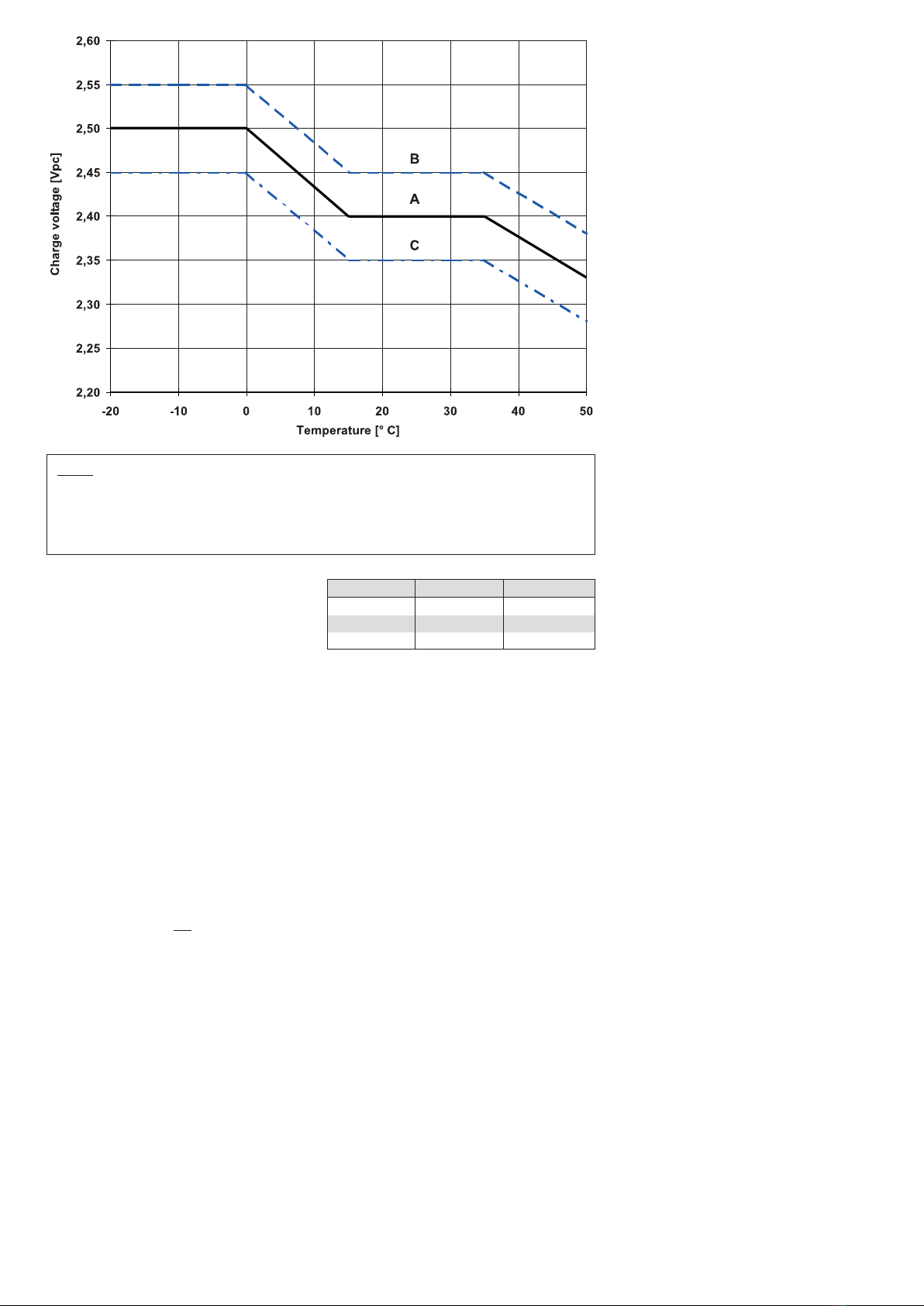
Fig. 1: Charge voltage vs. temperature for solar mode. Charge modes:
1) With switch regulator (two-step controller): Charge on curve B (max. charge voltage)
for max. 2hrs per day, then switch over to continuous charge – Curve C
2) Standard charge (without switching) – Curve A
3) Boost charge (Equalizing charge with external generator): Charge on curve B for max.
5hrs per month, then switch over to curve C.

Discharge time 1 h 5 h 10 h 20 h 100 h
Capacity C1[Ah] C5[Ah] C10 [Ah] C20 [Ah] C100 [Ah]
S 12 / 6.6 S 2.9 4.6 5.1 5.7 6.6
S 12 / 17 G5 9.3 12.6 14.3 15 17
S 12 / 27 G5 15 22.1 23.5 24 27
S 12 / 32 G6 16.9 24.4 27 28 32
S 12 / 41 A 21 30.6 34 38 41
S 12 / 60 A 30 42.5 47.5 50 60
S 12 / 85 A 55 68.5 74 76 85
S 12 / 90 A 50.5 72 78 84 90
S 12 / 130 A 66 93.5 104.5 110 130
S 12 / 230 A 120 170 190 200 230
Uf(cell) 1.7 Vpc 1.7 Vpc 1.7 Vpc 1.75 Vpc 1.80 Vpc
8. Technical data:
Capacities at different discharge times and final discharge voltage.
All technical data refer to 20° C.
8.1 Sonnenschein SOLAR
8.2 Sonnenschein SOLAR BLOCK
Discharge time 1 h 5 h 10 h 20 h 100 h
Capacity C1[Ah] C5[Ah] C10 [Ah] C20 [Ah] C100 [Ah]
SB 12 / 60 34 45 52 56 60
SB 12 / 75 48 60 66 70 75
SB 12 / 100 57 84 89 90 100
SB 12 / 130 78 101 105 116 130
SB 12 / 185 103 150 155 165 185
SB 06 / 200 104 153 162 180 200
SB 06 / 330 150 235 260 280 330
Uf(cell) 1.7 Vpc 1.7 Vpc 1.7 Vpc 1.75 Vpc 1.80 Vpc
8.3 Sonnenschein A 600 SOLAR
Discharge time 1 h 3 h 5 h 10 h 100 h
Capacity C1[Ah] C3[Ah] C5[Ah] C10 [Ah] C100 [Ah]
4 OPzV 240 123.6 167.4 193.5 218.0 290.0
5 OPzV 300 154.5 209.4 241.5 272.0 360.0
6 OPzV 360 185.4 251.4 290.0 326.0 430.0
5 OPzV 400 229.5 307.8 342.0 380.0 510.0
6 OPzV 500 275.4 369.6 410.5 456.0 610.0
7 OPzV 600 321.3 431.1 479.0 532.0 710.0
6 OPzV 720 367.3 513.6 626.0 681.0 830.0
8 OPzV 960 489.8 684.6 834.5 908.0 1110
10 OPzV 1200 612.2 855.9 1043 1135 1380
12 OPzV 1400 734.7 1026 1252 1363 1660
12 OpzV 1700 785.7 1161 1336 1519 1910
16 OPzV 2300 1047 1548 1782 2025 2550
20 OPzV 2900 1309 1935 2228 2532 3180
24 OPzV 3500 1571 2322 2673 3038 3820
Uf(cell) 1.67 Vpc 1.75 Vpc 1.77 Vpc 1.80 Vpc 1.85 Vpc

NXSSOOE5PDF00809 · Druckhaus Bechstein · Printed in Germany · Subject to change
56029045 5,0 IX.07
Exide Technologies GmbH
Im Thiergarten
63654 Büdingen – Germany
Tel.: +49 (0) 60 42 / 81 544
Fax: +49 (0) 60 42 / 81 398
www.industrialenergy.exide.com
This manual suits for next models
2
Other Exide Camera Accessories manuals


Popular Camera Accessories manuals by other brands


Trojan
Trojan GC2 48V quick start guide

Calumet
Calumet 7100 Series CK7114 operating instructions

Ropox
Ropox 4Single Series User manual and installation instructions

Cambo
Cambo Wide DS Digital Series Main operating instructions

Samsung
Samsung SHG-120 Specification sheet

Ryobi
Ryobi BPL-1820 Owner's operating manual