Exmark ULTRAVAC Manual

ULTRAVAC®
LazerZ®
SetupInstructions
ForUltraVacSerialNos.790,000&Higher
(totLazerZ(LZ),LazerZAS(LAS),andLazerZXPUnits352,000–789,999)
(totLazerZXSUnits352,000&Higher)
LooseParts
Usethechartbelowtoverifythatallpartshavebeenshipped.Partnumbersnotshownareavailableonthedealer
extranet.
DealerPack
Part#DescriptionQty.Use
116-0128Diverter,MuferW/Screw1Installingthemuferdiverter
3296-2Nut,Nyloc#10-24inch3
3256-61Washer3
32105-13Screw,HWH#10-24x3/4inch3
Assemblingthetubes.
—WarrantyRegistrationReminderFillouttheonlinewarrantyregistration
form.
LiteraturePack
Part#DescriptionQty.Use
—Manual,Operator’s1
—Manual,Parts1Readbeforeoperatingthemachine.
ModelNumbers
LZUV52–FitsLazerZ(LZ)andLazerZAS(LAS)with52inchdeck.
UV60–FitsLazerZ(LZ),LazerZAS(LAS),andLazerZXPUnits352,000–789,999andLazerZXSUnits352,000
andHigherwith60inchdeck.
UV6672–FitsLazerZ(LZ),LazerZAS(LAS),andLazerZXPUnits352,000–789,999andLazerZXSUnits
352,000andHigherwith66inchor72inchdeck.
©2008—ExmarkMfg.Co.,Inc.
P .O.Box808
Beatrice,NE68310
PartNo.4500-410Rev.A
PrintedintheUSA
AllRightsReserved

ModelsandRequiredCompletingKits
Note:UsethefollowingchartstoverifythekitsrequiredfortheunityouareinstallingtheUltraVacon.
UNITSERIALNUMBERREQ’DTOMOUNTULTRAVAC
LazerZ524(IncludesAS)510,000to789,999103-7416DriveKitand
103-5633FrontWeightKit
LazerZ524(IncludesAS)352,000to509,999103-2997DriveKit*
LazerZ604(IncludesAS)510,000to789,999109-1179DriveKitand
103-5633FrontWeightKit
LazerZ604(IncludesAS)352,000to509,999109-1189DriveKit*
LazerZXS604440,000to599,999109-1193DriveKitand
103-5633FrontWeightKit
LazerZXP604352,000to599,999109-1193DriveKit*
LazerZ724(IncludesAS)510,000to789,999109-1194DriveKitand
103-5633FrontWeightKit
LazerZ724352,000to509,999109-1191DriveKit*
LazerZXS724440,000to599,999109-1194DriveKitand
103-5633FrontWeightKit
LazerZXP724352,000to599,999109-1194DriveKit*
LazerZ605Triton600,000to789,999109-1167DriveKit
LazerZXSAir-Cooled605Triton600,000&Higher109-1167DriveKit
LazerZXSLiquid-Cooled
605Triton600,000&Higher109-1167DriveKitand
109-2203FloorPanWeight
LazerZ665Triton600,000to789,999109-1168DriveKit
LazerZXSAir-Cooled665Triton600,000&Higher109-1168DriveKit
LazerZXSLiquid-Cooled665Triton600,000&Higher109-1168DriveKitand
109-2203FloorPanWeight
LazerZ725Triton600,000to789,999109-1169DriveKit
LazerZXSAir-Cooled725Triton600,000&Higher109-1169DriveKit
LazerZXSLiquid-Cooled725Triton600,000&Higher
109-1169DriveKitand
109-2203FloorPanWeight
*Unitswitha2-postfoldableROPSinstalledwillalsorequiretheuseof103-5633FrontWeightKit.
2

AssemblyDiagrams
52LZandAS
352,000-509,999
52LZandAS
510,000-789,999
60&72LZ
andAS
352,000-509,999
AllXS,XP
Below600,000
&60AS
510,000-789,999
60&72LZ
510,000-599,999
AllLZ
600,000-789,999
withTriton
deck
AllXSAir
Cooled600,000
&Higher
AllXSLiq.
Cooled600,000
&Higher
ItemDescriptionQuantity
1BagAssembly2233333
2UpperTube1111111
3LowerTube1111111
4#10-24CRPH
Screw
3333333
5#10-24Nyloc
Nut
3333333
6#10FlatWasher3333333
7HoodAssembly1111111
8Blower
Assembly
1111111
9BaggerMount
Weldment
1111111
10BeltCover1111111
11CasterWeight2222222
12Jackshaft1111111
13BlowerDrive
Belt
1111111
14FrameBracket
RH
11
15FrameBracket
LH
11
16FrameBracket22222
17MountSpacer22244
18MountPin
Weldment
11111
19ClevisPin4444444
20HairPin(large)4444444
21ChutePivotPin1111111
22HairPin(small)1111111
233/8-16x11/4
HexScrew
88814141414
243/8Whizlock
Nut
881113131313
253/8SpringDisc
Washer
12121214141414
26BlockerPlate
(small)*
11
27BeltShieldStud11111
283/8-16x.75
HexScrew
33333
29BeltCover
Spacer
1-60only1-60only1-60only1-60only1-60only
307/16Spring
DiscWasher
2-60only2-60only2-60only2-60only2-60only
31WeightBracket2222222
3

52LZandAS
352,000-509,999
52LZandAS
510,000-789,999
60&72LZ
andAS
352,000-509,999
AllXS,XP
Below600,000
&60AS
510,000-789,999
60&72LZ
510,000-599,999
AllLZ
600,000-789,999
withTriton
deck
AllXSAir
Cooled600,000
&Higher
AllXSLiq.
Cooled600,000
&Higher
ItemDescriptionQuantity
323/8-16Square
HeadBolt
4444444
33WeightPlate44445
345/16-18x1.75
HexScrew
44444
5/16-18x1.5
HexScrew
44444
355/16Flat
Washer
44444
365/16-18
Whizlocknut
66444
37BeltCover
Support
22
38Knob11
395/16-18x.75
HexScrew
22
40Plug1111111
41WeightPlate
Weldment
1111
42Weight
MountingPlate
2222
43Hairpin2222
44DrillTemplate11111
45Spacer666
46Nut,NylocThin222
47Washer111
48DeectorPlate111
49Diverter,
Mufer
W/Screw
1
Items21,22,26,29,30,37,38,39,44,46,48,&49
notshown.
*OnlyrequiredforunitswithSerialNumbers351,999
andbelow.
SeeFigure15forinstallationofitems29&30.
SeeFigure13forinstallationofitem48.
SeeFigure7foritem46.
SeeSteps4and5intheInstallationoftheBlower
Assembly–52inchUnitsOnlysectionforinstallationof
37,38,and39.
4

Figure1
AllLazerZXP&LazerZXSandLazerZSerialNumber510,000&Higher
(ShownwithoutROPSforclarity)
*LazerZXSLiquid-CooledUnitsSerialNumber600,000andHigher
requireanadditionalweight(item33)onthefrontpanel.
Figure2
LazerZSerialNumber352,000–509,000AssemblyDiagram
(ShownwithoutROPSforclarity)
5

Safety
SafetyAlertSymbol
ThisSafetyAlertSymbol(Figure3)isusedbothin
thissetupinstructionsandonthemachinetoidentify
importantsafetymessageswhichmustbefollowedto
avoidaccidents
Thissymbolmeans:ATTENTION!BECOME
ALERT!YOURSAFETYISINVOLVED!
Figure3
1.Safetyalertsymbol
Thesafetyalertsymbolappearsaboveinformation
whichalertsyoutounsafeactionsorsituationsandwill
befollowedbythewordDANGER,WARNING,or
CAUTION.
DANGER:Whitelettering/Redbackground.Indicates
animminentlyhazardoussituationwhich,ifnotavoided,
Willresultindeathorseriousinjury.
WARNING:Blacklettering/Orangebackground.
Indicatesapotentiallyhazardoussituationwhich,ifnot
avoided,Couldresultindeathorseriousinjury.
CAUTION:Blacklettering/Yellowbackground.
Indicatesapotentiallyhazardoussituationwhich,ifnot
avoided,Mayresultinminorormoderateinjury.
Thismanualusestwootherwordstohighlight
information.Importantcallsattentiontospecial
mechanicalinformationandNoteemphasizesgeneral
informationworthyofspecialattention.
InstallingtheHoodAssemblyand
theBags
ForLazerZUnitsSerialNumber
510,000–789,999:
Note:ReferenceFigure1andFigure2fortheitem
numberscalledoutintheinstallationinstructions.
1.TemporarilyremovetheROPStoallowfor
installationoftheUltraVac.Retainthehardware
forreuse.
2.WheninstallingtheUltraVacontoaliquid-cooled
LazerZ,therearbumperplatemustberemoved.
Removerearbumperplate.Reattachthelowerside
bumperbarstothevertical“HOT”engineguard
shieldusingtwooftheoriginalscrews,washersand
whizlocknutsremovedfromthebumperplate.
3.Removethelowertwoscrewsholdingtheclutch
guardplate(“HOT”engineguardonliquid-cooled
units)totherearframeoftheLazerZunit.
4.Installthemountweldment(item9)looselytothe
rearofthemachineusingthetwoboltsandnuts
removedinstep2.
5.Installtheframebrackets(item16)andspacers
(item17)looselytothemountweldment(item9)
asshown.Secureusingfour3/8-16x11/4inch
screws(item23),four3/8springdiscwashers(item
25)andfour3/8-16inchwhizlocknuts(item24).
Makesurethattheraisedportionofthespringdisc
washerfacestheheadofthescrew(seeFigure4).
Figure4
6.Installtheframebrackets(item16),andROPSlower
rollbartubeslooselytothemountingpadsonboth
sidesoftheLazerframe.Usethehardwaresupplied
inthepartsbag:eight3/8-16x11/4inchscrews,
eight3/8springdiscwashersandeight3/8-16inch
whizlocknuts.Makesurethattheraisedportionof
thespringdiscwasherfacestheheadofthescrew
(seeFigure5).
6

Figure5
1.3/8-16x11/4inch
capscrews
3.3/8-16inchwhizlocknuts
2.Springdiscwashers
LazerZUnitswithSerialNumber
352,000–509,999:
Note:ForunitswithROPSinstalled,temporarily
removetheROPStoallowforinstallationoftheUltra
Vac.Retainthehardwareforre-use.
1.WheninstallingtheUltraVacontoaliquid-cooled
LazerZ,therearbumperplatemustberemoved.
Removerearbumperplate.Reattachthelowerside
bumperbarstothevertical“HOT”engineguard
shieldusingtwooftheoriginalscrews,washersand
whizlocknutsremovedfromthebumperplate.
2.Removethelowertwoscrewsholdingtheclutch
guardplate(“HOT”engineguardonliquid–cooled
units)totherearframeoftheLazerZunit.
3.Installthemountweldment(item9)looselytothe
rearofthemachineusingthetwoboltsandnuts
removedinstep2.
4.Jacktherearoftheunitupandsafelysupportiton
jackstands.Removetherearwheels.
CAUTION
Raisingthemowerforserviceormaintenance
relyingsolelyonmechanicalorhydraulic
jackscouldbedangerous.Themechanicalor
hydraulicjacksmaynotbeenoughsupportor
maymalfunctionallowingtheunittofall,which
couldcauseinjury.
DoNotrelysolelyonmechanicalorhydraulic
jacksforsupport.Useadequatejackstandsor
equivalentsupport.
5.Installtherightandlefthandframebrackets(items
14and15)looselytothemountweldmentandwheel
channelsonbothsidesoftheLazerZframe.The
angesonthesideplatesshouldfaceintowardsthe
unittoprovidethemaximumtireclearance.
6.Secureusingeight3/8-16x11/4inchbolts(item
23),eight3/8springdiscwashers(item25)andeight
3/8-16inchwhizlocknuts(item24).Makesurethat
theraisedportionofthespringdiscwasherfaces
theheadofthebolt.
G007237
1
Figure6
ForUnitswithaROPS
1.DoNotinstallthisscrewatthistime.
Note:OnunitswithaROPSinstalled,thelower
frontscrewthatattachestothewheelmotorchannel
mustbeleftuninstalled.UnitswithSerialNumber
440,000through509,999willhaveacapturedboltin
thisposition(seeFigure6).
Note:On52inchand60inchunits,thelowerbolt
onthewheelchannelisbestinstalledbypositioning
thenutbehindtheholeusingadeepsocketand
turningtheboltthroughtheholeintothenut.
7.ForUnitswithROPS:alignthreespacers(item45)
oneachsideandtapewithmaskingtapetotherear
frameasshowninFigure7.
7

UnitswithoutROPSskiptothe“AllUnits”section
tocontinueinstructions.
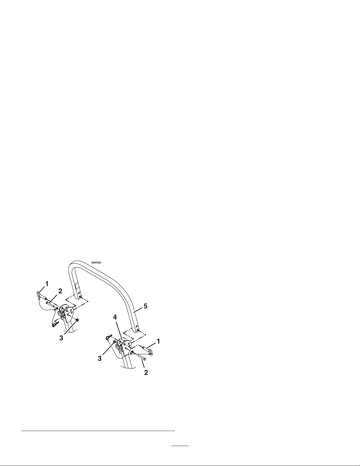
Figure7
1.Lowerrollbartubes5.3/8-16inchthinnylocnut
(item46)
2.Alignspacersandtapeto
frame.
6.3/8-16x41/2inch
capscrew
3.Raiserearofunithereand
supportwithjackstands.
7.3/8-16x11/2inch
capscrew
4.Wheelnuts
8.Alignlowerrollbartubesalongwheelmotor
channelsasshowninFigure7.
9.Looselyinstallthelowerrollbarhardwaretothe
tubesinthefollowingorder(referenceFigure7for
alignmentandinstallationinstructionsbelow).
10.Discardthe3/8-16inchregularnylocnutprovided
withtheLazerZunitorROPSkitandreplacewith
the3/8-16inchthinnylocnut(item46)provided
withthisUltraVac.
11.Installthe3/8-16inchthinnylocnut(item46)anda
springdiscwashertotheboltprotrudingfromthe
wheelmotorchannelasshown.
Note:Besurethespringdiscwasherconeis
installedtowardsthenylocnut.
UnitswithSerialNumber399,999andlowerrequire
useofa3/8-16x11/2inchscrew,springdisc
washerandwhizlocknut.Theseitemsareincluded
withROPSkitnumberFRPSLZ.
Note:On60inchunits,thelowerboltonthe
wheelchannelisbestinstalledbypositioningthenut
behindtheholeusingadeepsocketandturningthe
boltthroughtheholeintothenut.
12.Installone3/8-16x11/2inchhexcapscrew,spring
discwasherand3/8-16inchwhizlocknuttothetop
frontholeasshown(itwillbenecessarytopushthe
capscrewthroughthemaskingtapeappliedinstep
7).
13.Installone3/8-16x11/2hexcapscrew,springdisc
washerand3/8-16inchwhizlocknuttothetop
rearholeasshown(itwillbenecessarytopushthe
capscrewthroughthemaskingtapeappliedinstep
7).
Installone3/8-16x41/2hexcapscrew,springdisc
washerand3/8-16inchwhizlocknutthroughthe
toptubeasshown(itwillbenecessarytopushthe
capscrewthroughthemaskingtapeappliedinstep
7).
Note:Besurethespringdiscwasherconeis
installedtowardstheheadofallcapscrews.
AllLazerZXPandLazerZXSUnits:
1.TemporarilyremovetheROPStoallowfor
installationoftheUltraVac.Retainthehardware
forreuse.
2.Installmountweldment(item9)looselytotherear
bumperusingthetwoholesprovided.Secureusing
four3/8-16x11/4inchscrews(item23),four3/8
springdiscwashers(item25)andfour3/8-16inch
whizlocknuts(item24).
3.Installtheframebrackets(item16)andspacers
(item17)looselytothemountweldment(item9)
asshown.Secureusingtwo3/8-16x11/4inch
screws(item23),two3/8springdiscwashers(item
25)andtwo3/8-16inchwhizlocknuts(item24).
Makesurethattheraisedportionofthespringdisc
washerfacestheheadofthescrew .
•ForLazerZXPUnitsseeFigure4.
•ForLazerZXSUnitsseeFigure8.
Figure8
4.Installtheframebrackets(item16),andROPSlower
rollbartubeslooselytothemountingpadsonboth
sidesoftheLazerframe.UsetheROPSmounting
hardware,eight3/8-16x11/2inchscrews,eight
3/8springdiscwashersandeight3/8-16inch
whizlocknuts.Makesurethattheraisedportionof
thespringdiscwasherfacestheheadofthescrew
(seeFigure5).
8

ForAllUnitswithaROPSinstalled:
1.Installtheupperu-shapedsectionoftherollbar.
(ReferenceFigure9foralignmentandinstallation
instructionsbelow):
2.Locatethelatchpinassemblies(pinandhairpin
connectedwithalanyard).
3.Installa1/2-13x31/4inchcapscrewinthewasher
onthelanyardofeachpinassembly.
Note:Makesurethebenttabinthewasherpoints
towardtheheadofthecapscrew .
4.Lightlyoiltheinsidesurfacesoftheear-shaped
platesattheupperendofthelowerrollbartubes.
5.Locatetheupperu-shapedsectionoftherollbar.
Installtheupperrollbarsectionusingone1/2-13x
31/4inchcapscrew(fromstep3)andone1/2-13
inchhexangelocknutoneachside.DoNotover
tighten.Makesureupperrollbarcanpivotfreely.
Note:Makesurethecapscrewandnutsareinstalled
withthenuttotheinsideoftherollbar.
Note:Makesurethetabonthelanyardwasheris
installedasshownandpointstowardthefrontof
theunit.
6.Raisetherollbarintotheuprightpositionandsecure
withthelatchpinassembliesoneachside.Install
latchpinfromoutersurfaceofrollbarassemblyand
securewiththehairpintotheinside.
7.Tightenthefrontknobsagainsttheupperrollbar
ends.
Figure9
1.Latchpinassembly4.Applyoiltoinsidesurface
ofearshapedplates.
2.1/2-13x31/4inch
capscrew
5.Upperrollbartube
3.1/2-13inchhexangelock
nuts
AllUnits:
TightenallhardwarethatattachestheUltraVacmount
tothemachineframe.Startwiththescrewsthathold
themountweldmenttotherearoftheunitandwork
forward.
AllUnitswithaROPSinstalled:
Torquealllowerrollbarhardwareattachedtothe
machineframeto30-35ft-lb(41-47N-m).
LazerZUnitswithSerialNumber
352,000–509,999:
Reinstalltherearwheelsandlowertheunitfromthe
jackstands.
AllUnits:
Applyalightcoatofgreasetothefrontandrearof
theuppertubeofthemountweldment.Installthe
hoodassembly(item7)ontothemountbyslippingthe
hookportionoverthetopmountingtubeofthemount
weldment.Securetheassemblytothemountusingthe
clevispins(item19)andhairpins(item20).
Installthebagassemblies(item1)byinsertingthehook
portionintotheslotsinthecrossbarofthehood
assembly.
InstallingtheBlowerAssembly
UnitsSerialNumber352,000–509,999
withoutSplinedBladeDriver:
1.Stoptheengine,removethekey,andwaitforall
movingpartstostop.
2.Lowerthedeckfully.Removetherighthandbelt
cover.Removethebeltcovermountingstudthat
protrudesfromthedeck.
3.Removethedeckdrivebeltfromaroundtheright
handspindlesheave.
4.Supporttherightmowerbladeandshaftsothatit
willnotfalloutofthedeckwhentherightsheave
nutisremoved.
5.Removetherightsheavenut,springdiscwasher,and
sheavefromthespindleshaft.
Blockthebladerotationwithablockofwood
betweenthebladeandbafesasindicatedin
thebladeservicesectionoftheunitsOperator’s
manual.DoNotusethebladebolttoprevent
rotation.
9

6.ApplyalightcoatofMobilHTSgrease(orfood
gradeantisieze)tothetopportionofthespindle
shaftwherethesheavemounts.
7.Installthedoublesheave(item12)ontotheright
spindleshaft.Installthespringdiscwasherand
nut.Makesurethatthespringdiscwasherconeis
installedtowardsnut(seeFigure10).Torquethe
sheavenutto140-145ft-lb(190–197N-m).
Blockthebladerotationwithablockofwood
betweenthebladeandbafesasindicatedinthe
bladeservicesectionoftheLazerZOperator’s
manual.DoNotusethebladebolttoprevent
rotation.
Figure10
1.Torquesheavenutto
140-145ft-lb(190–197
N-m).
2.Installwithconetowards
nut.
Checkbladebolttorqueaftercompletingthis
installation.
Forunitswitha5/8-18x23/4inchbladebolt,
torqueto115-120ft-lb(156-163N-m).
8.Re-installthedeckdrivebeltinthelowergrooveof
thedoublesheave.Installtheplug(item40)intothe
boreofthedoublesheave.
9.Removethedischargechutefromthedeck.Discard
themountinghardware,butsavethedischargechute
foruseduringsidedischargeoperation.Thechute
pivotpin(item21)andhairpin(item22)maybe
storedinthepivotholesonthedischargechute
duringbaggingoperation.
UnitsSerialNumber599,999andLower
WithSplinedBladeDriver:
1.Stoptheengine,removethekey,andwaitforall
movingpartstostop.
2.Lowerthedeckfully.Removetherighthandbelt
cover.Removethebeltcovermountingstudthat
protrudesfromthedeck.
3.Removetherightsidebeltshieldandthe5/16x3
1/4inchboltthatsecurestheshieldtothedeck.
4.Removethebladefromtherightspindle.
5.Insertspecialtool109-2979intosplinedendof
spindleshaft.
6.Removetherightsheavenut,springdiscwasher,and
drivesheavefromthespindleshaft–keephardware
forre-use.
Usespecialtool109-2979toholdspindlefrom
rotating.DoNotusethebladebolttoprevent
rotation.
7.ApplyalightcoatofMobilHTSgrease(orfood
gradeantiseize)tothetopportionofthespindle
shaftwherethesheavemounts.
8.Installthedoublesheave(item12)ontotheright
spindleshaft.Installthespringdiscwasherand
nut.Makesurethatthespringdiscwasherconeis
installedtowardsnut(seeFigure11).Torquethe
sheavenutto140-145ft-lb(190-197N-m).
Usespecialtool109-2979toholdspindlefrom
rotating.DoNotusethebladebolttoprevent
rotation.
Figure11
1.Sheavenut-torqueto140-145ft-lb(190-197N-m)
2.Springdiscwasher(conetowardsnut)
3.Doublesheave(item12)
4.Specialtool109-2979
9.Reinstallthebladeandtorqueboltto:
Forunitswitha1/2-20x2inchbladebolt,
torqueto50-60ft-lb(75-81N-m).
10

10.Reinstallthedeckdrivebeltinthelowergrooveof
thedoublesheave.Installplug(item40)intoboreof
doublesheave.
11.Removethedischargechutefromthedeck.Discard
themountinghardware,butsavethedischargechute
foruseduringsidedischargeoperation.Thechute
pivotpin(item21)andhairpin(item22)maybe
storedinthepivotholesonthedischargechute
duringbaggingoperation.
UnitsSerialNumber600,000and
Higher:
1.Stoptheengine,removethekey,andwaitforall
movingpartstostop.
2.Lowerthedeckfully.Removetherighthandbelt
cover.Removethebeltcovermountingstudthat
protrudesfromthedeck.Savetheknobforlateruse.
3.Removethebladefromtherightspindle.
4.Insertthespecialtool109-2979intosplinedendof
thespindleshaft.
5.Removetherightsheavenylocnut,washer,and
splinedwasherfromthespindleshaft.DoNot
removethebladedrivesheave.Retainthenutfor
lateruse.
Usespecialtool109-2979toholdspindlefrom
rotating.DoNotusethebladebolttoprevent
rotation.
6.InstalltheUltraVacdrivesheaveontotheright
spindleshaft.Installthewasherthatissuppliedwith
theUltraVacdrivekit(item47)andthenutremoved
instep5.Torquethesheavenutto:5/8-18inchnut
(15/16Hex)to90-110ft-lb(122-149N-m).
Usespecialtool109-2979toholdspindlefrom
rotating(seeFigure12).DoNotusetheblade
bolttopreventrotation.
Figure12
1.5/8-18inchSheave
nut-torqueto90-110ft-lb
(122-149N-m)
3.UltraVacdrivesheave
(item12)
2.Washer(item38)4.Specialtool109-2979
7.Reinstallbladeandtorqueboltto:
Forunitswitha1/2-20x2inchbladebolt,
torqueto50-60ft-lb(75-81N-m).
8.Reinstallthedeckdrivebeltinthelowergroveof
thedoublesheave.Installplug(item40)intobore
oftopsheave.
9.Removethedischargechutefromthedeck.Discard
themountinghardware,butsavethedischargechute
foruseduringsidedischargeoperation.Thechute
pivotpin(item21)andhairpin(item22)maybe
storedinthepivotholesonthedischargechute
duringbaggingoperation.
10.Installdeector(item48)atthefrontrightcornerof
deckasshowninFigure13.Usecarriagebolt,nut
andwasherthatretainsrightcornerofadjustable
frontbafe.
11

Figure13
52InchUnitsOnly:
1.Removethebeltguideontheblower(Figure14).
2.Installthebelt(Item13)includedinthecompleting
kitontotheblowerassemblyasshown.
3.Reinstallthebeltguideremovedinstep1.
Figure14
ViewFromT opofBlower
1.Springloadedidler4.Beltguide
2.Impellersheave5.Decksheave(ref)
3.Fixedidler
4.Usingtheknobthatwasremovedwiththeoriginal
beltcoverstudandtheknobincludedwiththe
completingkit(item38),mountthetwobeltcover
supports(item37)totheplasticbeltcover(item
10).Positionthebeltcoveronthemowerdeck.
Thelowerendsofthebeltcoversupportsshould
restontheoutsideofthedeckstiffeners.Markthe
locationofthebeltcoversupportholesonthedeck
stiffeners.Removethebeltcover.Centerpunchand
drill3/8inchholes.
5.Removethebeltcoversupportsfromthebeltcover
andmountthemtothedeckusingthe5/16-18x3/4
inchscrews(item39)andwhizlocknuts(item36)
60,66,and72InchUnitsOnly:
1.Installthebeltcovermountingstud(item27).
For60inchunitsonly,installthespacer(item29),
two7/16springdiscwashers(item30)andthe
plasticknob(seeFigure15).Theknobdoesnot
needtobetightenedagainstthewashersatthistime.
Figure15
1.Knob3.Mountingstud(item27)
2.Springdiscwashers(item
30)
4.Spacer(item29)
2.Installthemountingpinweldment(item18)tothe
blowerassemblyusingthe3/8-16x3/4inchbolts
(item28)andwhizlocknuts(item24).Maximum
deckclearancewillbeprovidediftheboltsare
installedfrombelowthemountingpin.Themount
pincanbeinstalledintwopositions.For60inch
decks,SerialNumber599,999andLower,thepin
shouldbeinstalledasfarawayfromthebumperend
aspossible.Forall72inchdecksand60inchand66
inchdecksSerialNumber600,000andHigher,the
pinshouldbeinstalledclosetothebumperend(see
Figure16).
12

Figure16
1.Positionfor60inchUnits
SerialNumber599,999
andLower
2.Positionforall72inch
Unitsand60inchand66
inchUnitsSerialNumber
600,000andHigher
3.Installthebelt(item13)ontotheblowerbyworking
itaroundtheimpellersheave.
Figure17
BlowerLatchPosition
1.AllUnitsSerialNumber
600,000andHigherwith
Tritondecks.
2.LazerZ,LazerZXP ,and
LazerZXSUnitsSerial
Number599,999and
LowerandallLazerAS
Units.
4.Mountthebloweronthedeckbyslidingthe
mountingpinintothetubeattherearrightcorner
ofthedeck.Swingtheblowerclosed.Adjustthe
positionofthefrontpintoengagetheslotinthe
frontofthedeck.Usethelatchtolocktheblower
inthisposition.Adjustthetensiononthelatchto
holdthebloweruptothedeck,yetallowforrelease
byhand.
5.Pullthespringloadedidlerbackandslipthebelt
overthetopdeckspindlesheave.
6.Installtheplasticbeltcover(item10).On60inch
and66inchunitstheoutsideendofthecover
isslottedandcanslipbetweenthetwowashers
assembledinstep1intheUnitsSerialNumber
600,000andHighersection.Theplasticknobdoes
notneedtoberemoved.On72inchunitsthecover
hasahole,andtheplasticknobmustbeinstalled
afterthecoverhasbeenpositioned.
OnUnitsSerialNumber600,000and
HigherwithTritonDecks:
AdjustdoglegbafetomatchUltraVacblowerintake
opening.Adjustingtoowidemayallowobjectstobe
thrownfromunderthemowerdeckathighspeed.
Adjustingtoonarrowmaycausepluggingissues.
WARNING
Ifthedeckdischargeopeningandtheblower
intakeopeningdonotmatchcorrectly,it
willallowobjectstobethrowninoperator’s
orbystander’sdirection.Also,contactwith
bladecouldoccur.Thrownobjectsorblade
contactcancauseseriousinjuryorkillyouor
bystanders.
Adjustdoglegbafetomatchintakeopening.
InstallingtheMuferDiverterfor
LZUV52
ForLAS28KA524UnitsSerialNumber
670,000–789,999Only:
1.LocatethemuferdiverterintheDealerPack.
2.Removeanddiscardthescrewthatsecuresspark
arrestorinthemuferoutlettube.
3.Installthediverteroverthemuferoutlettubeand
securewiththenewlongerscrewprovided.Ensure
thatthesparkarrestorremainsinplaceinsidethe
outlettube.
InstallingtheWeightAssembly
AllUnitsSerialNumber599,999and
LowerandLiquidCooledXSUnits
SerialNumber600,000andHigher
Only:
Note:WeightplatesarenotrequiredonAir-Cooled
TritonUnitsSerialNumber600,000andHigher.
Thefourweightplates(item33)mustbeinstalledunder
thefrontpaneloftheoorpan.Theseweightsgive
properbalancetothemachinewhentheremovable
portionsofthebaggerareremoved.
UnitsbelowSerialNumber600,000withthe2post
foldableROPSinstalledrequireadditionalmounting
13

plates(item42)andafrontweight(item41)tobe
installed.Thefrontweightisremovableandretained
byusinghairpins(item43).
UnitsSerialNumber439,999and
Lower:
1.Locatethepositionofthemountingholes.Clamp
aweightplatetothefrontoftheoorpan(see
Figure18).Theearsontheweightplateshouldbe
towardsthebottom(upsidedownfromtheactual
mountedposition).Alignthebottomedgeofthe
weightplatewiththebottomedgeoftheoorpan
frontpanel.Centertheweightplatesidetoside.
Markthepositionofallfourholesusingacenter
punch.
2.Drill3/8inchholesatthepointsmarked.
Figure18
1.Positionearsonweightas
shown.
2.Alignplatestothisedge
tolocateanddrillholes
(Notethepositionofears).
ForUnitsSerialNumber439,999and
LowerwithoutaROPSInstalled:
Installthefourweightplatesbehindthefrontpanel
usingthe5/16-18x13/4inchscrews,5/16inch
washersand5/16-18inchwhizlocknuts(items34,35,
and36).Theweightplateswillonlytwiththeears
locatednearthebendintheoorpan(seeFigure19).
Thedecalontheoutsideoftheoorpanwillstillbe
visiblewiththeweightplatesmounted.
Figure19
ForUnitsSerialNumber439,999and
LowerwithaROPS:
1.Installfourweightplatesbehindthefrontpanel
andtwoweightmountingplates(items33and39)
asshowninFigure20usingfour5/16-18x2inch
screws,four5/16inchatwashers,andfour5/16-18
inchwhizlocknuts(items34,35,and36).
Figure20
2.Hookweightplateassembly(item40)overthetop
oftheweightmountingplatesandsecurewithtwo
hairpins(item42)asshowninFigure20.
Note:Theremovableweightisheavy.Usecare
whenlifting.Makesurethatyoucanholdthe
weightsecurelybeforelifting.Usecautionwhen
positioningyourhandssothatyouDoNotset
theweightdownonyourhandsorngers.
ForUnitsSerialNumber
440,000–599,999:
1.Locatethepositionofthemountingholesbyaligning
thetemplate(P/N103-5865)onthefrontfaceofthe
oorpanasshowninFigure21.Clampthetemplate
inplace.Usingacenterpunch,markthepositions
oftheholesontheoorpan.Flipthetemplateover
andrepeatontheotherendoftheoorpanface.
14

Figure21
1.Aligntemplatealongthesethreeedges.
2.Drill3/8inchholesatthepointsmarked.
3.Installfourweightplatesbehindthefrontpanel
andtwoweightmountingplates(items33and39)
asshowninFigure22usingfour5/16-18x2inch
screws,four5/16inchatwashers,andfour5/16-18
inchwhizlocknuts(items34,35,and36).
Figure22
4.Hookweightplateassembly(item40)overthetop
oftheweightmountingplatesandsecurewithtwo
hairpins(item42)asshowninFigure22.
Note:Theremovableweightisheavy.Usecare
whenlifting.Makesurethatyoucanholdthe
weightsecurelybeforelifting.Usecautionwhen
positioningyourhandssothatyouDoNotset
theweightdownonyourhandsorngers.
ForLazerZXSLiquid-CooledUnits
SerialNumber600,000andHigher:
1.Locatethepositionofthemountingholesbyaligning
thetemplate(P/N103-5865)onthefrontfaceofthe
oorpanasshowninFigure21.Clampthetemplate
inplace.Usingacenterpunch,markthepositions
oftheholesontheoorpan.Flipthetemplateover
andrepeatontheotherendoftheoorpanface.
2.Drill3/8inchholesatthepointsmarked.
3.Installthefourweightplatesbehindthefrontpanel
andoneweightplateonthefrontusingthe5/16-18
x13/4inchscrews,5/16inchwashers,and5/16-18
inchwhizlocknuts(items34,35,and36).The
weightplateswillonlytwiththeearslocatednear
thebendintheoorpan(seeFigure19).Thedecal
ontheoutsideoftheoorpanwillstillbevisible
withtheweightplatesmounted.
InstallingtheRemovableWeights:
Note:Theremovableweightsareheavy.Usecare
whenliftingthem.Makesurethatyoucanhold
themsecurelybeforeliftingthem.Usecaution
whenpositioningyourhandssothatyouDoNot
setthemdownonyourhandsorngers.
1.Assembletheweightbrackets(item31)tothe
removableweights(item11)usingthe3/8-16inch
squareheadbolts(item32)and3/8inchwhizlock
nuts(item24).
Unit11/2inch
Bracket
2inchBracket
LazerZ52inch
Units,All
11
LazerZAS60
inchUnits,All
1*1
LazerZ60inch
Units-NonTriton1*
1
LazerZ60inch
Units-Triton2
LazerZ66inch
Units2
LazerZAS72
inchUnits
2
LazerZ72inch
Units
2
LazerZXP60
inchUnits
2
LazerZXP72
inchUnits
2
LazerZXS60
inchUnits
2
LazerZXS66
inchUnits
2
LazerZXS72
inchUnits
2
*11/2inchbracketisincludedinUltraVac
completionkit109-1179or109-1189.
2.Installtheremovableweightassembliesoverthe
casterarms.Onall52inchunitsandsome60inch
unitsoneweighthasawidemountingbracketand
onehasanarrowbracket.Theywillonlytthe
machineoneway.Weightsforallotherunitsare
interchangeableleftandright.
3.Installaclevispin(item19)andhairpin(item20)on
eachcasterweighttoretainthem.
4.Tightenknobonweightassemblyuntiltheweightis
clampedsecurelytothecasterarm.
15

Figure23
AssemblingtheTubes
1.Sliptheupperandthelowertubestogether.
2.Inserttheuppertubeintothehopperseal–pushin
thenpulloutsothatthesealisextendedoutward.
3.Aligndimpleonuppertubewithendofhopperseal
andpositionverticallybetweenthetwoscrewsas
showninFigure24andFigure25.
Figure24
52InchUnit
1.Dimple
Figure25
60,66,and72InchUnits
1.Dimple
4.Setthedeckinlowestcuttingposition.
5.Slidelowertubeontoblowerandlatch(makesure
thatuppertubedoesnotmoveoutofalignment).
6.Drill7/32inchholesinlowertubeusinguppertube
holesasreference(seeFigure26).
7.Removethetubesfromunitandassembletheupper
(item2)andthelowertubes(item3)usingthree
#10-24x3/4inchhexwasherheadscrews(item4),
three#10washers(item6),andthree#10-24nyloc
nuts(item5).Thescrewheadshouldbeinstalled
totheinsideofthetubetoprovideminimum
obstructiontoow .Makesurethattheupperand
thelowerendsareorientedproperlyasthetubesare
assembled.(Partinglinesshouldroughlybelinedup.)
Figure26
1.Drilltheholeshere
8.Sliptheupperendofthetubeassemblyintothe
hoodopening.Slidethelowerendofthetube
assemblyoverthebloweroutletandalignthenotch
withthetubelatch.Latchthetubetotheblower.
16

Operation
Pre-Start:
1.ReadtheOperator’smanualforthemowerand
UltraVactofamiliarizeyourselfwithallcontrols
beforeoperatingthemachine.Makesurethat
youunderstandthecontrols,theirlocations,their
functions,andtheirsafetyrequirements.
2.Ensuretheblower,beltcover,bags,tubeandhood
areingoodcondition,properlyattached,andlatched.
RunIn
1.Verifythattheblowerdriveoperatescorrectlyprior
todeliverytocustomer.
2.TheUltraVacbloweroperateswhendeckdriveis
engaged.Besurethatallpersonsareclearofthe
mowerdeckandblowerbeforeengagingthecutting
blades.Setthethrottleto“midway”position.Pull
outwardonthePTOswitchtothe“ROTATE”
position.
3.Todisengagethedeckdriveandblower,setthe
throttleto“midway”position.PushinonthePTO
switchtothe“STOP”positiontostopthecutting
bladesandblower.Thecuttingbladeswillrequirea
slightlylongeramountoftimetocometoacomplete
stopwhentheblowerisinstalledonthedeck.
52InchUnitsOnly
1.Runtheunitwiththebladesandblowerengagedfor
twominutes.Disengagetheblades,stopengine,wait
forallmovingpartstostopandremovekey.Engage
parkingbrake.
2.Removethebeltcoverandchecktomakesurethat
thebeltisridingnearthecenteroftheatidleron
theidlerarm.Ifthebeltisnotridingnearthecenter
oftheidler,removetheblower,andbendtheidler
armslightly.
3.Reinstalltheblowerandbeltcoverandperform
steps1and2againtoverifybeltposition.
FillOutWarrantyRegistration
Form
Fillouttheonlinewarrantyregistrationform.
17
Other manuals for ULTRAVAC
1
Table of contents
Other Exmark Industrial Equipment manuals
Popular Industrial Equipment manuals by other brands

Bacci
Bacci MASTER Use and maintenance instruction manual

MCS
MCS DHP 20 instruction manual

FRIEDHELM LOH
FRIEDHELM LOH Rittal SK 3363 Series Assembly and operating instructions

Rohde
Rohde TE Series operating instructions

Rockwell Automation
Rockwell Automation 194R-SC1 Operating

Dover
Dover DESTACO ROBOHAND CH Series Service manual