Expert Electronics ColibriNANO User manual

Expert Electronics
2017
ColibriNANO
Direct Sampling HF/6M receiver
User Manual
V1.0

2
Expert Electronics
2017
1. Introduction ......................................................................................................................4
2. Technical characteristics..................................................................................................5
3. Hardware description .......................................................................................................6
4. Connect the ColibriNANO to a PC ...................................................................................8
5. Local operation ................................................................................................................9
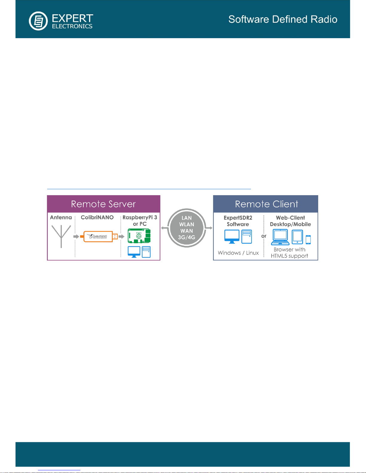
6. Remote operation ..........................................................................................................10
7. ExpertSDR2 Software Description .................................................................................11
7.1. Global controls panel ..................................................................................................11
7.2. Software receiver settings...........................................................................................13
7.2.1. Receiver control panel .............................................................................................13
7.2.2. Frequency and S-meter indicators ...........................................................................16
7.2.3. DSP control panel ....................................................................................................18
7.2.4. Panorama description ..............................................................................................21
7.2.4.1. Spectrum Scope ...................................................................................................21
7.2.4.1.1. Spectrum Scope scaling ....................................................................................22
7.2.4.1.2. Frequency tuning ...............................................................................................23
7.2.4.2. Waterfall................................................................................................................24
7.3. Status bar....................................................................................................................25
8. ExpertSDR2 software fine tuning ...................................................................................26
8.1. Device menu ...............................................................................................................27
8.1.1. Device settings.........................................................................................................27
8.1.2. VAC tab....................................................................................................................27
8.1.3. DSP tab....................................................................................................................28
8.1.4. Expert tab.................................................................................................................30
8.2. Sound card menu........................................................................................................31
8.2.1. Sound card...............................................................................................................32
8.2.2. Line output ...............................................................................................................32
8.3. Display menu ..............................................................................................................33
8.3.1. Main window tab ......................................................................................................34
8.3.2. Spectrum tab............................................................................................................35
8.3.3. Waterfall tab.............................................................................................................37
8.3.4. Grid tab ....................................................................................................................38
8.3.5. Filter tab...................................................................................................................38
8.3.6. Background tab........................................................................................................39
8.3.7. Indicators tab ...........................................................................................................40
8.4. САТ menu...................................................................................................................40
8.5. Panel menu.................................................................................................................42
8.6. Features menu............................................................................................................47

3
Expert Electronics
2017
8.7. Manager menu............................................................................................................48
8.8. CW Skimmer menu.....................................................................................................49
8.9. Shortcuts menu...........................................................................................................50

4
Expert Electronics
2017
1. Introduction
If you’ll spend just 30 - 45 minutes to read this manual, you will be able to easily begin
operating the ColibriNANO receiver and enjoy a modern way of listening the air. This manual
will answer most of your questions.
Quick and efficient mastering of the ColibriNANO receiver requires a basic PC knowledge.
We hope that the Windows terms, which are used in this guide are familiar to the user and
won’t cause any difficulties. To make this manual more user-friendly, we used screenshots
of dialogue windows; necessary functions are highlighted with colored contour.
Since the ColibriNANO is an SDR, it means that you will need a PC or laptop to use the
receiver. You can control your receiver with the ExpertSDR2, HDSDR or SDRSharp software
installed on your PC. The main features of this receiver are the 14-bit ADC @ 122.88 MHz,
Blocking Dynamic Range (BDR): 110 dB and sensitivity: 0.35 uV.
There is no signal processing path, in its classical meaning, in this receiver. The signal is
digitized from the antenna and all the other signal processing happens in the software.

5
Expert Electronics
2017
2. Technical characteristics
Modes
LSB/USB/DSB/CW/AM/SAM/NFM/WFM
Receiving bandwidth, MHz
0.01 - 55
Receiving bandwidth in the undersampling mode,
MHz
0.01–500
Noise floor, dBm
1.9 MHz (160M) - 131
7.1 MHz (40M) - 130
52.5 MHz (6M) - 127
Sample rate with IQ stream resolution 24-bit, kHz
48, 96, 192, 384, 768
Sample rate with IQ stream resolution 16-bit, kHz
1536, 1920, 2560, 3072
Amount of software receivers
1 (+1 SubRX)
Sensitivity, uV
0.35
Blocking Dynamic Range (BDR), dB
110
IMD3 Dynamic Range, dB
95
Supply voltage range, V
4.5...5.5
Maximum antenna input voltage, without ADC
overload, mV (ATT=0 dB)
74 (Pk-Pk); 32.7 (RMS)
Maximum current consumption, A
0.41
Input impedance, Ohm
50
ADC clock frequency, MHz
122.88
ADC resolution, bit
14
Local oscillator stability, ppm
+/- 0.5
Local attenuator with 0.5 dB step, dB
from -31.5 up to +6
RF input with up to 15 kV ESD protection
SMA connector
Dimensions L x W x H, mm (inches)
90х25х17 (3 1/2" x 1" x 5/8")
Operating temperature, °C (°F)
from -10 up to +60 (14…140)
Weight, gram (ounces)
43 (1.52)

6
Expert Electronics
2017
3. Hardware description
ColibriNANO block diagram
Architecture description
Receive path consists of the following functional units:
Ant –antenna connector.
LPF –Low Pass Filter with 55 MHz bandwidth. This filter allows you to receive signals
in the first Nyquist zone and eliminates signals from the second Nyquist zone. It switches
ON/OFF automatically according to the panorama center, ON - inside the 0-55 MHz range
and OFF –above 55 MHz.
ATT - attenuator -31.5…0 dB with 0.5 dB step, it allows to “weaken” signals to eliminate
the receiver overload while receiving strong signals.
Driver –it’s purpose is to amplify the signal and transfer it to the ADC.
Preamp –preamplifier 0…+6 dB, it can additionally amplify signals.
TCXO –Temperature-Compensated Crystal Oscillator with 122.88 MHz frequency.
This is a high-stability oscillator with temperature instability 0.5 ppm.
ADC –high-speed Analog-to-Digital Converter with 14-bit resolution and 122.88 MHz
sample rate. ADC is the heart of the receiver; it is responsible for direct sampling of all signals
in the 55 MHz bandwidth.
FPGA –Field Programmable Gate Array. It makes all high-speed processing
operations. Inside the FPGA happens the first down conversion of signals. It is similar with
the first converter in a classic super-heterodyne, but all operations processed in a
mathematic order with binary logic.

7
Expert Electronics
2017
Controller –It controls all ColibriNANO systems and performs the data exchange
between the receiver and the USB controller.
USB FT232H –It performs the data exchange between the Controller and a PC.

8
Expert Electronics
2017
4. Connect the ColibriNANO to a PC
To operate the ColibriNANO receiver you’ll need:
Personal computer. Recommended characteristics:
2х or 4х core CPU - Intel Core i3, i5, i7 or equal AMD processor; software can work on
“weaker” CPU like Core2Duo or Dual-Core, but it may lead to an exceeding CPU load.
4 GB RAM;
40 GB free space on your HDD/SSD;
15…27 inch display;
Video card which supports OpenGL 1.5 or higher.
Antenna, tuned on the HAM bands, has to have impedance around 50 Ohm for those
bands, where you plan to operate.
Supported operating system: Windows 7-10 32/64 bit.
Check your version of the Microsoft Visual C++ (click the right mouse button on the Windows
Start button-> Programs and Features), before installation of the ExpertSDR2 software, if
your installed version is above the one offered during installation, select "cancel".
When you plug the ColibriNANO in your PC, Windows will automatically download required
USB driver (ensure PC is connected to the internet before connecting the ColibriNANO).
Then receiver will be detected by Windows as new device, that’s all, you may use the
ColibriNANO.
If Windows will not automatically download required USB driver, download drivers from one
of the links below and manually assign them to the undetected device in the Device Manager
menu. Dismiss Windows warning regarding unsigned software and proceed with the
installation.
CDM v2.12.26 WHQL Certified x64 for 64-bit PC
CDM v2.12.26 WHQL Certified x86 for 32-bit PC

9
Expert Electronics
2017
5. Local operation
Local operation is a standard way to use the ColibriNANO receiver. Make the following
connections as described below:
1. Plug the ColibriNANO in your PC;
2. Connect HF-antenna to the receiver antenna connector;
3. Open "Options”menu and ensure "device connected" is displayed. If not, get correct
driver.
4. Start the ExpertSDR2 software with the red Start button (left top corner of the software
window);
5. Open Options→Sound Card menu
and make sure that the Enable checkbox in
the Sound card block is set. See picture;
6. Click OK. If everything is done correctly, you will see the air noise on the panorama and
hear the sound in the headphones.

10
Expert Electronics
2017
6. Remote operation
To control the ColibriNANO via Internet we created the ExpertRemote system, based on the
client-server connection. This system allows you to place the receiver and server in the
remote location with low air noise and Internet connection. This might be some remote
village or place with no electrical interference and 3G/4G Internet (or any other connection
type). Using the ExpertRemote system you can enjoy clear air from your phone, tablet,
notebook or PC. Even simple antennas, placed in a "quiet" place, allows you to listen to the
far stations with low level.
Another feature of this system is that the receiver's software can be synchronized with
transceivers and be used as the panorama adapter with high resolution. Use the transceiver
to transmit signals, receive on your remotely located receiver via the ExpertRemote system.
Distant stations, rare (DX) stations or expeditions from now on will be a reality for you with
our ExpertRemote system!
More information about the ExpertRemote system you can find here.
ExpertRemote system block-diagram

11
Expert Electronics
2017
7. ExpertSDR2 Software Description
Software settings which won't be mentioned or addressed in this manual, are set by default
or provided to the user's self-study and experiments. All the unmentioned settings cannot
cause the fatal damage of the ColibriNANO receiver hardware, so you can safely experiment
with them. You're dealing with the software-defined radio –SDR, the main settings and signal
processing is held in the software.
7.1. Global controls panel
This panel consists of the following buttons:
-the Start button switches on/off the ExpertSDR2 software.
Attenuator level can be set in the drop down menu with a slider (0.5
dB step) or by successive presses of the indicator button, which
cycles upwards the attenuation coefficient with 5 db step, from -30dB
up to +5 dB.
- enable/disable button of the sound output from the PC's sound card.
- enable/disable button of the frequency memory panel.

12
Expert Electronics
2017
- Volume slider. This setting affects the LF output on the
receiver’s front panel and PC's sound card output. Speaker icon has the mute function.
- in the Profile manager menu you can:
add a new profile, by entering the name of the profile in the “Profile name” field and
pressing Add button.
set the settings of the whole program to the default state, by the Default button.
Update the settings of the certain profile from the list to the current settings.
Remove the certain profile from the list.
Note! All new profiles will be stacked up to the drop-down menu as a new line.
- Options menu will be fully described later in the Paragraph#9 of the manual.
- About button opens the new window with the info about current version of the
ExpertSDR2 software:
- pressing the Fullscreen mode button will unfold the software window on the whole
screen.

13
Expert Electronics
2017
7.2. Software receiver settings
These settings are divided in four logical parts:
7.2.1. Receiver control panel
- volume and balance control menu for the first and second receivers separately.
- button opens an 18-band equalizer menu.

14
Expert Electronics
2017
Equalizer has an indicator below the VFO A frequency
tab (enabled on the picture).
- button enables the VAC (data exchange via virtual audio cables).
- button enables the squelch. Displayed as the vertical yellow needle on the S-meter.
If the air signal –green needle, surpasses the SQL trigger threshold –yellow needle, then
you'll hear the sound of the received station on the receiver's LF output. If the signal level is
lower than the trigger threshold, you'll hear nothing.
- button mutes LF signal.
- show the HF stations markers on the panorama from the EiBi data base. Hover with
the mouse pointer on the station frequency
and you’ll see its name.
-IQ-files recording is required for storing the RX bandwidth panorama. The file is
saved to the "C\Users\User\ExpertSDR2\wave”.
- turn on the CW Skimmer.
- bigger S-meter button. The S-meter window can be separated from the software
window and moved to any place on the screen.
When you enable the NFM mode, one additional buttons appear:
- Continuous Tone-Coded Squelch System button. In some cases, it's required to
activate the squelch with the help of the CTCSS tones. You set the CTCSS level relatively
to your voice signal.
To operate in the CTCSS mode:
1. Set the NFM mode.

15
Expert Electronics
2017
2. Set the receiver's tone frequency in the RX Tone input-box.
3. Press the CTCSS button to activate the CTCSS mode.
4. Receive signals with CTCSS tone.
When you enable the WFM mode, one additional button appears:
- when enabled, this function allows the software to automatically detect whether the
station is strong or not and lets you to listen to it in stereo mode.
-
AGC sensitivity control slider (Automatic Gain Control on classic
transceiver).
Panel of mode buttons:
-Amplitude Modulation.
- Synchronous Amplitude Modulation.
- Double Side Band.
- Lower Side Band.
- Upper Side Band.
- CW mode.
- Narrow FM.
- Wide FM, supports receiving of the stereo signals.
- Spectrum mode. Receive the pure signal without any demodulation (panadapter
bandwidth). The idea is to receive pure signal then pass it out via VAC or PC’s soundcard.
- Digital Lower Side Band. Connect a third-party software (is not supplied) to the
receiver software for operating in digital modes.
- Digital Upper Side Band. Connect a third-party software (is not supplied) to the
receiver software for operating in digital modes.
- Digital Radio Mondiale, 10 kHz filter with 5 kHz IF to work with external decoder of
the DRM signals. Connect third-party software (is not supplied) to the receiver software for
decoding of the DRM signals.

16
Expert Electronics
2017
160M –2M –amateur bands.
GEN –if out of the amateur bands.
7.2.2. Frequency and S-meter indicators
Mainly, this panel consists of the visual indicators, like the VFO A/B frequencies, signal level
on the antenna's input (S-meter) and several control buttons.
Displaying elements:
Frequency indicator of the VFO B (sub-receiver).
Note! You won’t hear the audio from the VFO B if it is out of the panorama bandwidth.
Frequency indicator of the VFO A (main
receiver).
S-meter - by default this scale displays the
power level of the signals in the RX filter
bandwidth. The scale has two grade types: in
S-units and in dBm. The signal strength displayed in dBm to mW (yellow figure) in the top
left corner of the S-Meter.
Note! S-Meter in the ExpertSDR2 has two different calibrations for HF (0-30 MHz) and VHF
(30-300 MHz). HF and VHF signals with the same dBm level has different S-scale values.
For example: HF S9 = -73 dBm = 50 uV (50 Ohm), VHF S9 = -93 dBm = 5 uV (50 Ohm).
S-Meter in the ExpertSDR2 corresponds to the IARU recommendations, each device is
calibrated at the manufacturing.
ADC type displays the power in each
quadrature channel (double scale) in RX mode.
Sub-receiver control unit:
SubRX –enable sub-receiver. If you want to listen to the VFO A and VFO B frequencies
simultaneously, use the Sub-receiver.
1. Activate the Sub-receiver by pressing the button.
2. Set the required VFO B frequency.

17
Expert Electronics
2017
3. Listen to the VFO A and VFO B frequencies simultaneously.
Note! You can switch the point and click control on the panorama between VFO A and VFO
B receivers, by pressing the middle mouse button. You’ll control the RX with the same color
to the mouse cursor.
When you change the band the SubRX is disabled.
B>A –assign the VFO B frequency to VFO A
A>B –assign the VFO A frequency to VFO B
B<>A –swap frequencies between the VFO A and VFO B
Main receiver control unit:
LOCK –lock the VFO A frequency tuning.
SAVE –save the current VFO A frequency and mode type in the memory panel.
SET –manual input of the frequency to VFO A or VFO B.
Band Stacking Memories indicator (VFO A
only). Each memory slot has a frequency,
mode, and filter settings. Each band has three
memory slots associated with it. Successive presses on a band button will cycle through the
stored memory slots. It might be useful for quick frequency and mode changes within a band.
To replace one memory slot:
1. click the required band button you would like to modify.
2. change the frequency (within a selected band), mode, and filter to the required settings.
3. click the band button again to save the values.

18
Expert Electronics
2017
Navigation buttons. The quick memory cells are
automatically stored with the frequencies if the receiver
stands still over a second. Then those frequencies can
be selected in order back and forth, as in an internet
browser. Total stack contains 16 cells.
7.2.3. DSP control panel
- Receive Incremental Tuning.
RIT offset means that signal receiving will be
held on a frequency + Rit offset. Offset is
displayed as a translucent band on the
spectrum scope. Tuned frequency displayed
as the red line. RX frequency displayed as the
green line with the filter band (on the picture
you can see USB mode).
In the drop-down menu you can set the frequency offset in Hz. Reset
-resets the offset value to zero.
You may enter the frequency offset value in the input box via keypad, or by clicking on the
required frequency on the spectrum scope. At the same time the following values will be
displayed below the main receiver's frequency indicator:

19
Expert Electronics
2017
R IT: - the frequency offset.
L: and H: - low and high filter's edges
frequencies.
O: - mouse cursor frequency inside the filter.
To change the filter bandwidth: move the
mouse cursor over the filter edge, it will be
highlighted, then drag the edge with the left
mouse button.
When the RIT is enabled, frequency tuning changes a bit:
Press and hold the left mouse button inside the RX filer to move it over the panorama.
Press and hold the left right button inside the RX filer to move the whole panorama with the
filter.
Press and hold the middle mouse button inside the RX filer then move the mouse cursor out
of the filter bandwidth, the O: indicator will show the frequency difference between the mouse
cursor and the RX filter.
Note! If the RIT offset wasn't reset, when you disable the RIT it's state will be saved. When
you activate the RIT next time, the offset will equal the previous value.
-AGC presets menu.
In the drop-down menu you can select the receiver's AGC preset:
OFF - AGC is off.
LONG - preset with long AGC reaction (approximately 750 ms). Recommended
for phone modes.
SLOW - preset with slow AGC reaction (approximately 500 ms). Recommended
for phone, digital modes.
MED - preset with medium AGC reaction (approximately 250 ms). Recommended for CW,
digital modes.
FAST - preset with fast AGC reaction (approximately 100 ms). Recommended for CW, digital
modes.
USER - preset with custom AGC reaction (by default the slowest 1000 ms).
Note! AGC settings influence the quality of the received signal. Be careful selecting the AGC
preset or tuning your own preset.

20
Expert Electronics
2017
Step list allows to change the step in range from 0.1 Hz to 100 kHz.
DSP functions:
- enable the RX equalizer (enabled on the picture).
- binaural audio mode (in one of the headphone channels, the signal will be shifted in
phase on 90 degrees).
- enable the adaptive Noise Reduction to clean the signal from noise interferences.
- enable the First Noise Blanker for impulse interference.
- enable the Second Noise Blanker for impulse interference.
Note! The NB1 and NB2 algorithms are different. Try each of them to reach the best impulse
interference reduction. NB1 and NB2 Noise Blankers can be used simultaneously.
- enable Automatic Notch Filter for adaptive rejection of the narrowband interference
in the receiving band (interference, carrier signals, CW signals, etc.).
Note! If there are no interference, ANF could slightly affect the reception quality of the
desired signal. Disable ANF, if you don't need it.
- enable Analog Pick Filter, it creates the triangle filter's AFC (amplitude-frequency
characteristic) in the filter bandpass.
- enable Digital Surround Effect for CW signals, it provides a space orientation in stereo
phones.
Note! This algorithm provides panorama acoustic of the CW signals in the filter bandwidth,
depending on their position in the filter:
- if the received CW signal is in the receive filter bandwidth and lower the tuned frequency,
it will be louder in the left phone;
- if the received CW signal is in the receive filter bandwidth and higher the tuned frequency,
Other manuals for ColibriNANO
1
Table of contents
Other Expert Electronics Receiver manuals