5 of 13
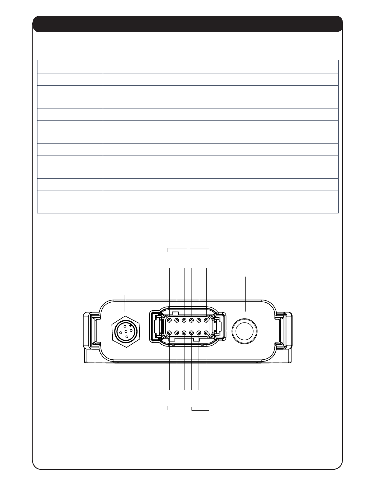
2.4 UNIT SWITCH SETTINGS
During initial installation, the unit needs to be opened and switches set to match the units
interface connection.
If the unit is to be used with a xed source address style CAN bus interface, then the xed
address mode switch needs to be set to the ON position and the xed source address set in
the Hi and Lo order rotary switches. If the unit is to be used as an NMEA2000® sensor then the
Device Instance should be set in the two small rotary switches. These would normally both be
set to “0”
Modbus
It is possible to select Modbus baud rate and parity using SW1 ; please refer to the table 1
below. Note: Modbus is only available in NMEA2000®mode.
The 5801 MODBUS frame consists of 8 data bits, 1 parity bit, and 1 stop bit. Please refer to
Modbus specication for further information.
Modbus Commands
The 5801 Trim Tab Adaptor identies as slave 48 (0x30) and supports one command (0x3) [Read
Holding Registers].
Any request for registers not implemented will result in error code (0x2) [Illegal Address] to be
returned.
Any request for a command that is not implemented will result in error code (0x1) [Illegal
Instruction] to be returned.
Please refer to table 2 for memory locations.
Recommended Usage
We recommend that the device is polled at a maximum of once per second. Ideally this request
should handle all 3 registers; however, the ability to poll individual registers is implemented as
per MODBUS specication.
SW1 Baud Rate Parity
09600 Even
19600 Odd
219200 Even
319200 Odd
438400 Even
538400 Odd
6-F 9600 Even
Memory
Location Address H Address L Data H Data L
40000 00 00 00 Port Tab Pos
40001 00 01 00 Stbd Tab Pos
40002 00 02 00 Cent Tab Pos