Expert Electronics Colibri User manual

Contents
1. Operating rules
2. Technical characteristics
3. Operation mode description
4. Control elements, commutation, indication
4.1 Jack for operation the external devices.
. Preparation for work
.1 Connection to PC
.2 Tuning the Ethernet-connection
.3 Setting the IP address in Windows Vista/7/8/8.1
.4 Setting the IP address in Windows XP
. Changing the IP address of the receiver
6. Work description
6.1 Settings panel
6.2 Menu Device
6.3 Tuning the receiver
6.4 Sound Card Menu
7. Work in standard conditions
7.1 The remote work with the receiver
8. Configuration

Introduction
Distinguished customers! We would like to thank You for choosing the production of Russian
company Expert Electronics LLC! While the production of new H M devices we tried to take into
account all the wishes of both our and potential clients and to implement them in the most advanced
manufacturing and digital techniques of signal processing.
Now the development of the digital technologies as the application to the H M practice allows to
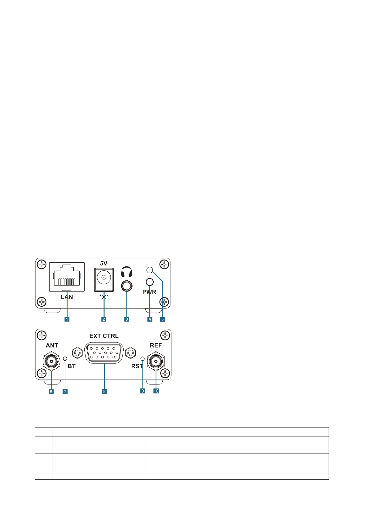
implement the best hardware characteristics of digital transceivers and receivers. Our experience in
the sphere of digital signal processing allows to pursue the excellent sound quality and the
opportunities for clearing the signal from noise.
The software methods of hardware controlling allow to configure the controlling of the receiver and
the transceiver flexibly based on your own preference.
Now in front of you is one of the most advanced and perfect receivers produced in the recent
decade.
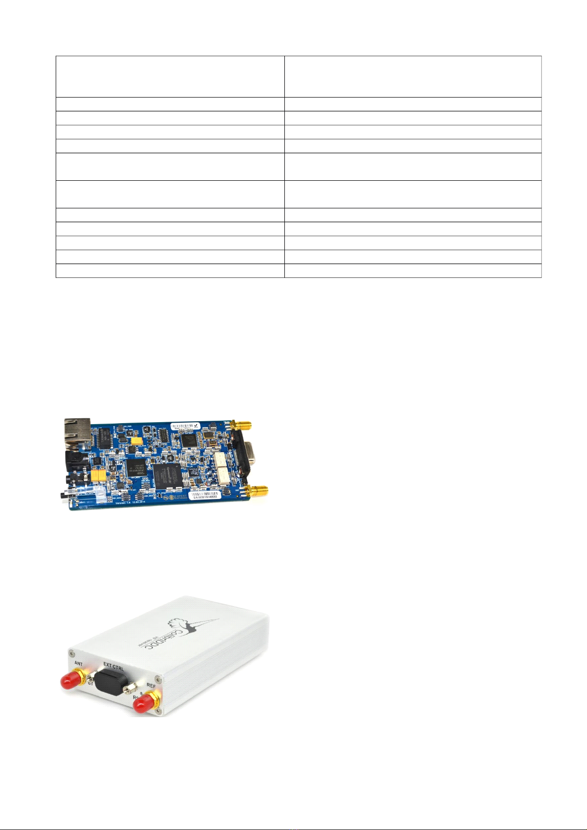
We would like to bring your attention a new Colibri receiver, which is produced in accordance with
the DDC technology. DDC technology means the usage of direct digitization of signal from the
antenna and the digital conversion of the signal down.
The principle is based on the digital digitization of the wide spectrum of signals practically directly
from the antenna, signal thinning and software signal bearing “down the frequency”. The signal is
software processed. The necessary modulation type is decoded and the image of the panorama of
the necessary spectral band is also formed.
The known method of the direct signal transformation from HF to LF is used as the basis. In
distinction from the previous generation of SDR receivers and transceivers, where the signal
transformation of the orthogonal (quadrature) signals was held on the hardware level, the software
bearing is applied in new receiver. It allows to suppress the inactive sideband, carrier frequency and
image channel practically ideally.
The band of the displayed frequency spectrum in the classical technology of the SDR- receipt with
signal conversion on the sound IF was bounded by the band of signal conversion of the sound card.
Now when the whole spectrum of the short-wave band is digitized, it is possible to display any band
within the digitization limits.
But that is not all! The amount of possible physical receivers is not limited by one receive path. In
Colibri there were implemented 4 software receivers and also there is an opportunity to
simultaneously observe the whole SWB.
bsence of IF signal conversion and digital demodulation algorithms allow to receive the
qualitative clear signal at the receiver's output.
Except monitoring with good visualization, the receiver's controlling program allows:
•to record the high qualified input signal
•to record the air mode in the frequency bandwidth and to reproduce it later
•choose any filter pass band from 10 Hz to 20 kHz with a good ramp
•operate any modulation modes, including the receipt of the radio stations of digital
broadcasting standard DRM.
With the introduction of new Colibri receiver came a new time for the radio amateurs who work in

VHF. The receiver's software allows to watch the presence and activity of the radio stations in VHF
and UHF bands with any modulation type and bandwidth to 62 MHz.
Over recent years the attention of a large number of radio amateurs was attracted by the SDR
theme. During the previous several years there were found both advantages and disadvantages of
the classical SDR-technology.
The large majority of the found disadvantages was excluded by switching to the technology of
direct signal digitization. Now we can declare that the receiver is ideal.
The big brands who produce the hardware for special application are interested in DDC technology.
So for example the SDR and DDC technologies are used in mobile communication technology,
military communication technology, wireless network hardware and that's not a full list.
So let's come to the description of DDC Colibri receiver, which is offered to all the radio amateurs
by Expert Electronics LLC.
ExpertSDR2 Software License Agreement
ExpertSDR2 Software is priceless. The program is supplied without any obligations. t this basis
Expert Electronics LLC shall be free from liability for any defects, damage or loss from the
Software. ll the users of the Software confirm the execution of this License greement.
Software can be used in any means except resale. Software can be copied, transferred and
distributed in any Internet resources without price.
ll the suggestions and comments over the program shall be sent to our e-mail: info@sunsdr.com
1. Operating rules
•Check the mechanic damages of the Colibri receiver (hereinafter Device) by the visual
examination before switching it to PC.
•Learn attentively the manual, before using the Device. Connecting and operation of the
Device without the instructions can bring to the fatal errors.
•If the Device was held in the climatic conditions, different from the operational, it is
recommended not to switch it on within 2 hours holding it in operational conditions.
•Connecting the Device to a PC should be done in accordance with the connection diagram,
given in the Manual.
•Check the presence of the ground connection of the PC and the ground wire of the antenna
Jack (SM ) of the Device before switching
•It is forbidden to connect the Device to PC with the voltage presence on it or in the switched
condition
•It is forbidden to use the power supply with the voltage more that +16V. Remember! The
device power is the voltage direct current
•Before connecting the external devices to Jack EXT CTRL read the Manual, learn the tables
and the schemes of connecting of the external devices.
•Remember! The transistor switches have the limitations over supply voltage and current,
going through them. The power swap is forbidden.

•It is forbidden to use the Device in the temperatures lower than —10ºC and higher than
+60ºC
•It is forbidden to use and store the Device in the dusted rooms and on exposure to direct
sunlight
•void exposure of the atmospheric precipitations on the Device. Never spill any liquids
(especially aggressive) on the Device.
•Don't open the Device. It contains the radio elements, which have the high-sensitivity to the
static electricity. This document contains all the necessary information about the internal
design to satisfy the curiosity of Users. To repair the Device ask the producer.
•lways shut off (disconnect) the Device's antenna, if you don't operate on it or if there
appear a danger of atmospheric electricity damage
•Save the Device, cables and wires from the influence of the magnetic pickups (emergency
states), out controlled currents and voltages and the domestic animals.
•To exclude the damage of the devices and not to produce the harmful interference on air
don't allow to control the Device people with the doubtful reputation
•Keep out of the reach of children
2. Technical characteristics
GENERAL CHARACTERISTICS
Receiving bandwidth HF: 0…62.5MHz
Receiver's bandwidth in the oversampling
mode
VHF: 62.5…800MHz
Modulation types SSB,CW,FM, M,DIGI
Jacks ntenna: 1 х SM (Famale)
External clock generator input: 1 х SM (Famale)
ntenna input impedance 50 Ohm
External clock generator input impedance 2 kOhm, 1pF (standard CMOS-input)
Input level of the external clock generator 1…3V
Working temperature band 0…+50ºС
Frequency temperature stability 0.5ppm
Frequency setting accuracy 1 Hz
Power voltage 5…7 V (5 V nominal)
Consumption (input) current 0.64
Size W 64 mm x H 24 mm x L 112 mm
Lightweight 1 kg
dditional jacks: Headphones: Stereo jack 3.5mm
Expansion Jack: DB-15
L N: RJ-45
Power: 5mm (2 mm central +)
CHARACTERISTICS OF THE RECEIVE PATH
Receive path type Digital with the direct signal digitization in the
receiving frequency

Sensitivity in CW mode, band 500Hz 1…62.5 MHz: 0.07 mkV
62.5…180 MHz: 0.5 mkV
180…800 MHz: 1…3 mkV
RF DC clock frequency 125 MHz
RF DC Capacity 14 bit
djacent channel attenuation (rejection ratio) 100 dB while detuning 100Hz
Spurious-response selectivity >60 dB (defined by the input filters)
Dynamic range (bandwidth) over blocking in
HF bandwidth
110 dB
Dynamic range (bandwidth) over blocking in
VHF bandwidth
106 dB
SFDR receiving path 85 dB in bandwidth 62.5 MHz
Sampling frequency of the inbuilt audio coder 40 kHz
Capacity of the inbuilt audio D C 24 bit
Output power of the LF path 50 mW
Output impedance of the LF path 0.25 ohm
3. Operation mode description
Colibri receiver is made on the basis of four-ply printed circuit board of size L 110 mm х W 60 mm.
ll the receiver's components are seat on the board by the surface mounting and installed on the
upper layer. The process of board assembling is fully automatized and is made on modern high-tech
industries of Taiwan. ll the receiver's functional parts are installed on the board under the screens.
ssembled board of the receiver is mounted into the light anodize case from alloy (aluminium
alloy). Hard case protects the receiver from external physical impacts and screen the board from
external electromagnetic emissions.
Electric diagram of the receiver is given at the figure below.

Receiver' s path consists of the following functional units:
•Ant – antenna jack. Inputs the signals.
•LPF – low frequency filter with the band 55 MHz. Filter allows to extract the first Nyquist
zone signal to exclude the receipt of signals from the second zone. This filter is necessary if
the receiver is used without external band filters. LPF can be switched off. In this case the
signal goes bypass the filter and further over the path.
•ATT – attenuator – 20 dB. ttenuator allows to loss the signal (strength) to exclude the
overload of the receiver during the receipt of the power signals. If the attenuator is switched
off, the signal goes bypass without loss.
•ADC – high speed analog-digital converter ( DC) with the sampling frequency 125 MHz
and the capacity 14 bit. DC is the heart of the receiver. It converts all the input radio
signals in the band 62.5 MHz into the digital readouts for further digital processing.
•FPGA - field programmable logic device (FPG ). Provides all the high speed operations of
the digital signal processing. FPG provides the primary signal conversion. The first down-
conversion is made here. It can be somehow compared with the first converter in the usual
superheterodyne, but all the operations are held mathematically with the binary logic.
•MCU – board microcontrol unit. Passes the data into the PC, receives data from PC and
operates all the systems of the Colibri receiver.
•LAN – Local rea Network. Data exchange in the Colibri receiver is provided with the
velocity 100 Mb/s over the local network. Such interface exchange between PC and the
receiver easily allows to connect the receiver and/or use for the connection the existing local
network
•PLL –inbuilt frequency synthesizer. Used for the receipt of the mounting clock frequency
125 MHz for clocking the DC. Two sources of the reference signal (TCXO and external
reference generator with the frequency 10 MHz) can be used as the reference generator for
PLL.
•TCXO – inbuilt temperature compensated crystal oscillator with the frequency 20 MHz.
This very stable generator with the temperature instability 0.5 ppm.
• REF - Jack for connecting the external very stable generator with the frequency 10 MHz.
ccording to the task and the requirements to the frequency stability, the necessary source
of the reference frequency can be used. It can be chosen in the Settings of the controlling
ExpertSDR2 program.
It should be mentioned that the stability and quality of the receiving signals depends on the
stability and phase cleanliness of the reference frequency sources.

•EXT CTRL - Jack for operating the external devices. The receiver contains 7 powerful
keys with open collector, which can be configured by User in accordance with the band. For
example range band filter, antenna switch, etc. can be operated.
•DAC – DC with the capacity 24 bit. This unit makes the reverse transformation of the
digital signals into the analog audio signal. This unit forms the sound in the receiver's
bandwidth and sends to the jack PHONES.
Colibri receiver, as all the range of Expert Electronics equipment with the direct signal digitization,
is designed so that the FPG and micro controller firmware can be updated in the automatic mode
by ExpertSDR2 program without the direct involving of User. Firmware installation program is
firmly hardwired into the receiver's hardware. It allows to firmware the receiver without concerns
over the power failure. If there appear problems with PC or electricity, renewing of the firmware
can be continued after the PC reboot or power recovery.
4. Control elements, commutation, indication
Colibri receiver has several external control elements. Face plate of the receiver includes jacks for
connecting the headphones and two types of microphones (dynamic and electret), three LEDs for
indication the working modes and the power engage switch. ll the rest controls are on the back
panel.
Table. Description of the control elements of the face panel
№ Description Comments
1 Local network jack Jack is used to connect the receiver to the local network by
L N – cable.
2 Power jack Jack is used to connect unipolar power source with the
voltage +5V and maximum load current 1 or more.
Receiver has the hardware protection from swap and power

excess
3Jack for connecting the
headphones
The headphones with the resistance 16-32 Ohm and active
speaker systems (dynamics) can be connected to this jack
4 On/off power button Power on/off is completed by pressing.
5
LED for indication the power
and installation of the
connection, green and yellow
color
LED indicates the working modes:
1. Switching on the receiver (circuit loading, local network
initialization) or lost connection – led blinks green
2. Connecting the receiver to the PC – burns the constant
yellow light
6Jack SM (Famale) for
antenna connection HF and VHF antennas are connected to this Jack
7 Button BT (Boot)
8External control jack Jack for controlling the external devices (pin definition is
given in the description below)
9Button for reset the IP-address
settings
The button is used to reset IP – address and USB – ports of
the receiver to the default values
ip: 192.168.16.200, ports: 50001, 50002.
10
SM (Famale) input of the
external reference generator 10
MHz
Signal from the very stable generator with the level 10 ..13
dBm and the frequency 10 MHz can be sent to this input
4.1 Jack for operation the external devices.
Two ways of connecting the external devices to the Colibri receiver are given in this chapter of the
manual: connecting with the optoisolator and without it. It should be mentioned that connection
with the optoisolator is preferable and more safety.
EXT CTRL jack is used for operating the external devices, such as preliminary low noise amplifier,
antenna switch, band boxcar. Operation is held from SDR-program.
Pin definition of the EXT CTRL jack which is placed on the face panel of the receiver is shown at
the figure below,
Description of the contacts (contact elements) of the EXT CTRL operation Jack
Description Comments
Х1-Х6 Contacts of the programming keys with open collector
СР Protective diode contact

+5V
Power source contact +5V, current to 100m .
ttention: connecting the demands with the current more
than 100 m is forbidden. It can bring to the receiver's
breakdown.
G Ground terminal of the receiver
I1, I2 Contacts for connecting the button detectors, works on the
input.
NC Contacts are not used
. Preparation for work
Preparation of the receiver to work is made up of two easy steps:
•Connecting the receiver to PC
•Tuning the Ethernet-connection of the PC (includes setting the IP-address of the PC and/or
the receiver)
.1 Connection to PC
To start the Colibri receiver you need:
•receiver power unit;
•PC;
•L N – computer network cable (supplied)
•ntenna, which is tuned on the amateur bands.
Each unit should have the characteristics given below.
Recommended power unit: should have the power not less than 10 W, voltage 5V and current not
less than 2 .
PC or notebook: any modern configuration.
Recommended configuration:
•2 or 4 core processor Intel Core i3, Core i5 or Core i7
•2, 4 or more R M
•40 gigabyte of free space on the hard disk for the receiver's program and accompanied
programs;
•15…27” monitor
•video card supporting the technology of OpenGL 1.5 and higher
Program will work on less powerful PCs with processors Core2Duo and Dual-Core, but it will bring
to the higher level of resources loading.

Operating system: OS set on the PC should be Windows XP 32/64 bit, Windows 7 32/64 bit or
Windows 8/8.1 32/64 bit. The latest versions are preferable.
While buying the PC ask the shop assistant about the OpenGL video card support.
LAN - computer network cable, connecting the receiver with the PC by Ethernet-connection
Antenna tuned on the amateur bands should have the resistance near to 50 ohm on those bands,
where is planned the work on air.
.2 Tuning the Ethernet-connection
Colibri receiver doesn't need the installation of special drivers. The whole information exchange is
carried out by the L N network interface.
Before installation of the receiver's software it is necessary to make the network connection
settings.
There are several ways to connect the receiver to the PC:
•Variant А: Connecting the receiver to the PC without tuning the fixed computer IP-address.
With such connection after tuning the receiver searches for the accessible address in the limits of
the pointed network within 3- seconds. If the address is not found, the receiver switches the DHCP
mode. That is the receiver by itself assigns the address to the PC in the limits of the programed
subnet and connects over the assigned address.
•Variant B: Connecting the receiver to a PC with the IP-address configured manually.
With such connection after tuning the receiver searches for the accessible address in the limits of
the pointed network and makes the connection.
Let's consider each way of connection more detail.
Variant A:
Connecting the receiver directly to the computer with a help of cable interface Ethernet (L N) with
the automatic IP address allocation.
•Connect the receiver to the PC by L N cable, which is supplied
•Connect the power cable
•Switch on the receiver
•Wait 30 seconds till the green LED stop blinking and start burning the constant yellow light.
•Check that the network connection settings are set on the automatic mode of IP-address
receipt.
•Call up the ExpertSDR2 program and click the button Settings.
•Tune the visibility of the receiver and other necessary parameters, save them.
•Push the On button of the receiver's panel.
Variant B1:

Connecting the receiver directly to the PC with a help of cable interface Ethernet (L N) with the
allocation of fixed IP address 192.168.16.Х
•Connect the receiver to the PC by L N cable, which is supplied
•Set the static IP-address 192.168.16.Х in Windows XP or Windows Vista/7/8 as it is shown
below.
•Switch on the receiver
•Call up the ExpertSDR2 program and click the button Settings.
•Tune the visibility of the receiver and other necessary parameters, save them.
•Push the On button on the receiver's panel.
Variant B2:
If you already have the local network with the IP address not 192.168.16.ххх and you need to
change the IP address in the receiver
•Connect the receiver to the PC by L N cable, which is supplied
•Set the static IP-address 192.168.16.Х in Windows XP or Windows Vista/7 as it is shown
below.
•Switch on the receiver
•Call up the ExpertSDR2 program and click the button Settings
•Change the IP address in the Colibri receiver as it is shown below
•Connect the receiver by the L N-cable to the local network.
•Now the program ExpertSDR2 can be called up at any computer in the local network
.3 Setting the IP address in Windows Vista/7/8/8.1
Press the button Start in the low left corner in Windows. Choose Control Panel. ppear the menu,
given at the figure below. In section Network and Internet choose View network settings and
tasks.

In the appeared window choose Change adapter settings
Choose network connection, where the Colibri receiver is connected to. fter that click the right
button of the mouse on the icon and in the drop-down menu choose Properties.
In the new window set the cursor on the Internet Protocol Version 4 and press the button
Properties.

If it is planned to use the automatic IP address allocation by the receiver, point Obtain an IP
address automatically and Obtain DNS server address automatically.
If it is planned to set the fixed IP-address, point 192.168.16. 0 and subnet mask 2 .2 .2 .0.
Those parameters are extended to the PC's network card. Instead figure 50 in IP-address can be
pointed any figure except 2 and 200. On default the Colibri receiver's IP-address is
192.168.16.200. fter setting press the button ОК. IP-address setting is finished.
.4 Setting the IP address in Windows XP
Press the button Start in the low left corner in Windows. Choose Control Panel. Then Network
and Internet choose Network Connection
Choose Network Connection

Choose network connection, where the Colibri receiver is connected to. fter that click the right
button of the mouse on the icon and in the drop-down menu choose Properties.
In the new window set the cursor on the Internet Protocol Version 4 and press the button
Properties.

If it is planned to use the automatic IP address allocation by the receiver, point Obtain an IP
address automatically and Obtain DNS server address automatically.
If it is planned to set the fixed IP-address, point 192.168.16. 0 and subnet mask 2 .2 .2 .0.
Those parameters are extended to the PC's network card. Instead figure 50 in IP-address can be
pointed any figure except 2 and 200. On default the Colibri receiver's IP-address is
192.168.16.200. fter setting press the button ОК. IP-address setting is finished.
. Changing the IP address of the receiver
Call up the ExpertSDR2 program and open the Settings menu Settings-> Device. Point the current
IP-address of the Colibri receiver in the margin SDR Address. By default it can be set the address
192.168.16.200 or automatically set address.
Choose category Expert. Further in the margin New IP Address set the new IP address, in our case
192.168.1.200 and press the button Set IP Address. fter this operation the Colibri receiver will be
accessible by the new address 192.168.1.200.

6. Work description
Colibri receiver allows to work in two modes. When the Colibri receiver stands near on the table,
the headphones can be connected directly to the receiver. In such a case the minimal signal delay is
provided. When the Colibri receiver is placed far from the PC, the mode of the remote work is used.
In this case the headphones are connected to the PC's sound card. ll the settings are made from the
ExpertSDR2 software menu.
To prepare the Colibri receiver for work it is necessary to learn the receiver's program settings and
the settings of the additional sound card. The window is called by pressing the button “Settings” in
the program interface.

Note!
Detailed description of the program is given in the document “ExpertSDR2 for the Colibri
receiver. User's guide”, which can be downloaded on our site.
6.1 Settings panel
Selection panel configuration contains a graphical representation of configuration sections,
separated by type of customizable features.
When choosing the right type of functions, menus and tabs appear with the knobs and buttons
related to a specific function or type settings.
•Menu Device - setting hardware and software signal processing functions.
•Menu Sound card - setting the audio output of the receiver through the PC's sound card.
•Menu Display - customize the appearance of the program and display signals' parameters.
•Menu CAT - setting the connection of the receiver to a PC via the C T interface.
•Menu Panel - setting receiver's operational panel E-Coder.
•Menu Futures - configuring an automatic accompanying programs launch.
•Menu Manager - Setup Manager, receiver's remote control capabilities. (Planned to
implement in the nearest future).
•Menu CW Skimmer – setting the connection with the program CW Skimmer.

6.2 Menu Device
Menu “Device” includes the tabs for setting the following functions:
•Setting computer communication parameters with the receiver and HF input tuning
•Tab VAC - configure the virtual audio cable
•Tab DSP - received signal processing settings
•Tab Ext Ctrl - setting the remote control input.
•Tab Expert - configuring IP-address of the receiver and the receiver's thin calibration.
6.3 Tuning the receiver
Left area is allocated for setting the basic system functions of receiver's program interaction with
hardware stuffing:
•Device - selection receiver's menu.
•SDR Address - the physical address of the IP receiver default 192.168.16.200 or the set
address
•SDR Port - the port number over which the data is transferred.
•Sample Rate - inverter's sampling frequency. Corresponds to the panorama swath. You can
select one of the 4-band values.
Buttons:

•Button Search – searching the receiver in the net. If all the PC's network settings are correct,
you will see your receiver and it's address in the appeared panel. Press the button Use to
choose the receiver for work.
•
•Button Information – displays the receiver's serial number, firmware revision, the printed
circuit revision number and installed options.
The button can be used as one of the variants of connection tests of program and the receiver. If the
connection is set the receiver's information will be seen, otherwise appear the connection failure.
Hardware settings:

•Use LPF – switching wide band filter (low frequency filter) over the receiver's input with
the band 0-62 MHz. Clear the check box if the receiver works in the wide band VHF
frequency modes oversamples 62-800 MHz.
•Disable audio output - switching receiver's audio input
6.4 Sound Card Menu
By default the output of the low-frequency signal from receiver is arranged through a hardware
circuit of the receiver. In the original version it can be headphones or powered speakers connected
to the receiver.
convenient way to output low-frequency signal from the receiver is to use a standard computer
sound card. In this case, the digital stream of low-frequency signal is routed from the receiver to the
computer. headset, such as used on Skype, can also be used to communicate easily and
comfortably with the receiver physically located, for example, in a remote area.
To activate the computer's sound card, set check box Enable in the menu Sound card.
Sound Card settings contain the following items:
•Driver - select the type of sound card driver.
•Input - input range of physical sound card.
•Channels - select the number of using sound card channels.
•Sample rate - the sampling frequency.
•Buffer size - size of the buffer.
•Latency - the signal delay time.
7. Work in standard conditions
Setting the receiver near the PC is considered to be standard conditions. In such conditions the
headphones are connected to the Colibri receiver.
Table of contents
Other Expert Electronics Receiver manuals