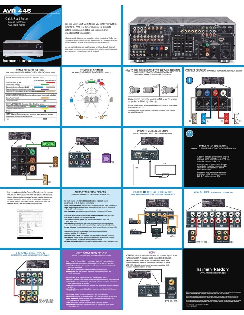
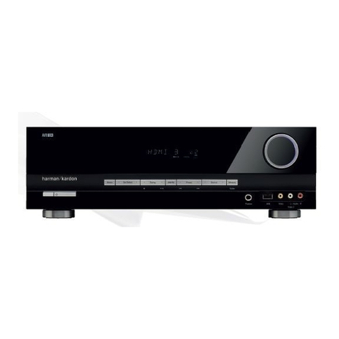
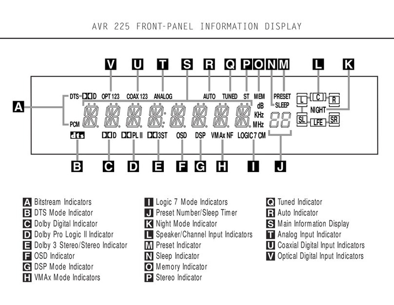
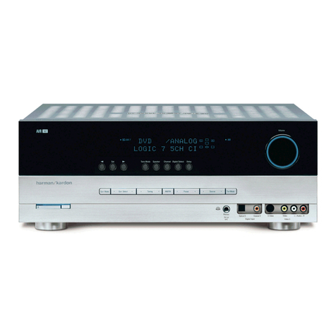
manuals.online logo
Brands
  1. Home
  2. •
  3. Brands
  4. •
  5. Harman Kardon
  6. •
  7. Receiver
  8. •
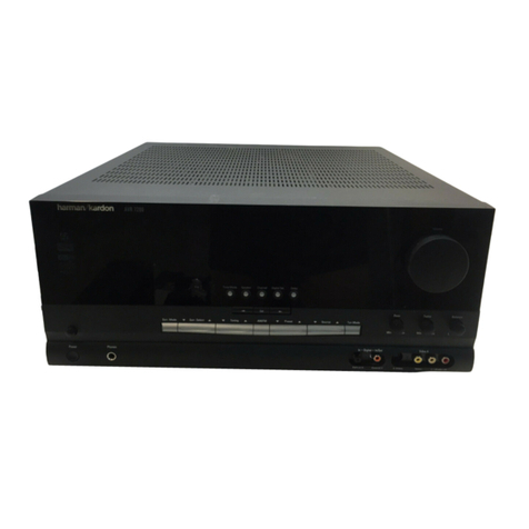
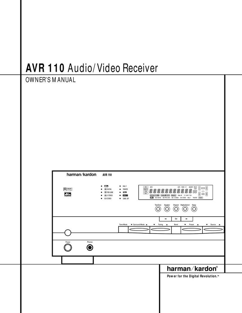
  9. Harman Kardon HK680I User manual

Harman Kardon HK680I User manual

harman/kardon
hk680i
owner's
manual
Speakers
LOUe
sODSOtM
defeat
fitter
Hy
Abb
bac
tab
Speaker
System
1
Speaker
System
4
Speaker
System
2
Speaker
System
2
Right
Left
Right
Left
Turntable
Dipole
Antenna
Wall
Outlet
Tape
Dec
me
6)
examen
1
eOOO00O
«oL}L]#\_/
8
Tape
Deck
2
Input
Other
Equipment
mionttor
tye
ihn
y
:
thaman
hantofy
be
Ese.
REPRE
|
v
Owner's
manual
hk680i
Your
investment
in
a
component
high
fidelity
sys-
tem
indicates
you
have
a
more
than
average
interest
in
music.
The
fact that
your
investment
includes
a
Harman
Kardon
Ultrawideband
Stereo
Receiver
shows
us
your
appreciation
of
uncompromised
reproduction
of
the
music
you
enjoy.
Throughout
the
design
and
manufacture
of
this
unit,
we
made
every
effort
to
assure
tt
will
meet
all
of
your
expectations.
To
ensure
continuing
high
performance,
read
this
manual
carefully
before
you
connect
and
operate
your
hk680i.
Warning
To
prevent
fire
or
shock
hazard,
do
not
expose
this
appliance
to
rain
or
moisture.
Warning
Do
not
mistake
the
ferrite
loopstick
AM
antenna
for
a
handle.
Its
bracket
cannot
support
the
unit.
Connections
For
the
moment,
leave
the
POWER
LINE
CORD
(53)
of
the
hk680i
unconnected.
Put
the
unit
on
the
shelf
or
table
where
it
will
be
installed.
Leave
enough
work-
ing
space
so
you
can
make
all
connections
easily.
The
hk680i
requires
adequate
ventilation.
It
should
not
be
installed
on
a
cushion
or
rug,
and
a
minimum
of
two
inches
(5cm)
clearance
should
be
provided
above
and
behind.
Like
most
stereo
equipment,
your
hk6801
is
fitted
with
pin
tyoe
RCA
connectors
to
accept
standard
pin
type
RCA
patch
cords.
If
these
are
not
compatible
with
your
other
equipment,
consult
your
audio
dealer
for
patch
cords
with
proper
adaptors.
Connecting
your
turntable
to
the
hk680i
Turntables
are
supplied
with
their
own
signal
cables.
Consult
the
owner's
manual
and
determine
which
cable
is
for
the
left
channel
and
which
is
for
the
right
channel.
Insert
the
left
channel
cable
into
the
left
PHONO
INPUT
connector
(44)
on
your
hk680i.
Insert
the
right
channel
cable
into
the
right
PHONO
INPUT
connector
(44).
Push
the
plugs
in
all
the
way
so
they
are
firmly
seated,
making
good
electrical
contact.
If
your
turntable
has
a
separate
ground
wire,
connect
it
to
the
knurled
thumbscrew
on
the
receiver
marked
GND
(42).
Connecting
your
tape
decks
to
the
hk680i
To
connect
a
tape
deck,
connect
the
left
output
connector
of
your
tape
deck
to
the
left
TAPE
1
INPUT
connector
(46)
on
your
hk680i.
Now
connect
the
right
output
connector
of
your
deck
to
the
right
TAPE
1
INPUT
connector
(46)
on
your
hk680i.
Using
a
second
pair
of
patch
cords,
connect
the
left
input
connector
of
your
deck
to
the
left
TAPE
1
OUTPUT
connector
(47)
on
your
hk680i.
Now
con-
nect
the
right
input
connector
of
your
deck
to
the
right
TAPE
1
OUTPUT
connector
(47)
on
your
hk680i.
Push
the
plugs
in
all
the
way
so
they
are
firmly
seated,
mak-
ing
good
electrical
contact.
A
second
tape
deck
may
be
connected
similarly
using
the
TAPE
2
INPUT
and
OUTPUT
connectors
(48)
(49).
Connecting
other
equipment
to
the
hk680i
A
pair
of
AUXILIARY
INPUTS
(45)
is
available
at
the
rear
of
the
hk680i
for
the
connection
of
any
“high
level”
output
equipment.
A
special
tuner
for
long
wave,
marine,
aircraft
or
citizen’s
bands,
etc.,
may
be
connected.
Or
you
may
choose
to
connect
the
output
of
the
audio
section
of
a
television
receiver.
Any
num-
ber
of
choices
are
available.
Consult
your
audio
dealer
for
information
as
to
what
equipment
is
com-
patible
with
your
hk680i.
Connecting
speakers
Use
two-conductor
stranded
wire
to
connect
your
speakers
to
the
receiver.
Eighteen
gauge
lamp
cord
(zip
cord)
is
satisfactory,
but
a
heavier
gauge
(16
or
14
gauge)
is
preferable,
especially
for
distances
over
25
feet.
Cut
two
segments
of
wire
long
enough
to
reach
each
speaker.
Separate
the
conductors
at
each
end
of
the
wire
segments
for
a
length
of
two
to
three
inches.
Then
carefully
remove
about
one-quarter
inch
of
insulation
from
each
free
end.
Twist
the
strands
of
each
conductor
so
they
are
smooth
and
tight
with
no
loose
strands.
Lamp
cord
usually
provides
a
“code”
that
differ-
entiates
the
two
conductors.
A
conductor
may
be
coded by
a
rib,
sharp
corner,
or
indentations
molded
along
the
length
of
the
insulation.
In
some
cases,
a
thin
colored
thread
is
molded
inside
the
insulation
of
each
conductor.
In
others,
one
conductor
is
darker
than
the
other,
or
the
insulation
of
each
conductor
is
of
a
different
color.
Connect
the
bare
ends
of
one
segment
of
lamp
cord
to
your
right
speaker
as
fol-
lows:
Connect
the
coded
conductor
to
the
speaker's
positive
(“+”)
terminal,
and
the
uncoded
conductor
to
negative
(“—”).
The
“+”
and
“—”
markings
are
in
gen-
eral
use,
allhough
some
speakers
use
other
labeling
systems,
such
as
“1”
and
“2,’
“A’
and
“B”
and
so
on.
Find
the
appropriate
row
of
speaker
connectors
on
the
receiver
marked
SPEAKER
SYSTEM
1
(50).
Push
in
on
the
red
plastic
head
of
the
connector
marked
RIGHT
to
reveal
an
opening
beneath.
Insert
the
bare
end
of
the
coded
conductor
into
the
open-
ing.
Release
the
connector.
The
conductor
should
now
be
locked
firmly
into
place.
Insert
the
uncoded
conductor
into
the
adjacent
black
connector
marked
GND.
Repeat
the
procedure
for
the
left
speaker,
taking
care
to
observe
the
coding
of
the
conductors
as
described
for
the
right
speaker.
If
the
code
is
followed
as
described,
your
speakers
will
be
connected
“in
phase”,
which
is
important
for
solid
bass
and
precise
lateral
location
of
the
sound
source.
To
connect
a
second
pair
of
speakers,
repeat
the
procedure
for
the
right
and
left
speakers
of
the
second
pair,
using
the
receiver
terminals
marked
SYSTEM
2
(51).
Connecting
an
AM
antenna
A
ferrite
loopstick
type
AM
ANTENNA
(36)
is
provided
and
can
be
rotated
to
improve
reception.
If
an
external
AM
antenna
is
used,
connect
it
to
the
terminal
marked
AM
(41).
Connecting
FM
antennas
If
no
outdoor
antenna
is
available,
connect
the
lugs
of
the
dipole
(supplied
with
the
unit)
to
the
FM3000.
BAL
terminals
(39)
and
(40).
The
dipole
can
then
be
tacked
or
taped
to
a
wall
or
the
back
of
a
shelf.
However,
reception
will
be
greatly
improved
if
the
receiver
is
connected
to
an
outdoor
FM
antenna
sys-
tem.
If
you
live
in
a
fringe
reception
area,
or
if
your
house
Is
situated
among
obstructions
(such
as
moun-
tains
or
tall
buildings},
you
may
need
a
more
power-
ful,
directional
FM
antenna.
To
connect
3000,
(ohm)
outdoor
antenna
wire,
attach
as
described
in
the
preceding
paragraph.
However,
if
your
cable
is
75
ohm,
as
is
the
case
with
many
outdoor
antennas,
it
will
be
round
with
either
two
protruding
wires
or
a
threaded
coaxial
connector.
If
the
cable
ends
in
bare
wires,
connect
the
wire
that
forms
the
outer
mesh
braid
to
the
terminal
marked
FM
75Q,
UNBAL
GND
(88).
Connect
the
solid,
cop-
per-colored
wire
protruding
from
the
center
of
the
cable
to
the
FM
3000,
BAL
terminal
(39).
If
your
750,
cable
has
a
threaded
coaxial
connector,
fasten
it
on
to
the
threaded
antenna
receptacle
(37).
AC
convenience
ouilets*
Three
AC
outlets
(52)
on
the
rear
panel
of
the
hk680i
provide
power
connections
for
turntables,
tape
decks
or
other
equipment.
One
is
marked
UN-
SWITCHED
and
provides
power
whether
the
receiver
is
turned
on
or
not.
Those
marked
SWITCHED
pro-
vide
power
only
when
the
receiver
is
turned
on.
If
you
have
completed
the
connections
above,
you
are
now
ready
to
place
the
hk680i
in
its
perma-
nent
position
and
plug
the
POWER
LINE
CORD
(53)
into
an
AC
outlet.
To
turn
the
unit
on
and
off,
press
the
POWER
switch
(2).
When
power
is
on,
the
POWER
indicator
(1)
will
light.
To
operate
your
hk680i
Speaker
selection
and
headphones
The
SPEAKER
1
(4)
and
SPEAKER
2
(5)
switches
select
the
pair
of
speakers
to
be
played.
When
either
switch
is
depressed,
the
corresponding
pair
of
speakers
Is
activated.
The
front
panel
HEADPHONES
Jack
(3)
accepts
headphones
for
personal
listening.
Headphones
may
be
used
simultaneously
with
speakers
if
desired.
To
play
records
Depress
the
PHONO
pushbutton
(15),
activate
your
turntable,
and
advance
the
VOLUME
control
(26)
clockwise
to
a
comfortable
level.
if
you
hear
a
hum
at
average
listening
levels,
turn
the
POWER
switch
(2)
off
and
check
to
see
that
phono
and
ground
connections
are
secure.
*In
some
countries,
owing
to
Safety
Agency
Electrical
requirements,
these
AC
receptacles
are
covered.
To
listen
to
broadcasts
When
you
first
turn
on
the
power,
the
STATION
DISPLAY
(33)
will
automatically
show
“FM
88.10
MHz,”
the
lowest
FM
frequency.
To
tune
to
an
FM
station
manually,
press
the
FM
or
AUTO
FM
pushbutton
(17)
(16)
and
place
the
TUNING
button
(25)
in
its
MAN-
UAL
position
(in).
To
scan
to
higher
frequencies,
press
the
TUNING
UP
button
(35),
releasing
it
when
the
desired
frequency
has
been
found.
To
scan
to
lower
frequencies,
press
the
TUNING
DOWN
button
(34).
During
scanning,
no
sound
will
be
audible
at
any
time,
even
as
you
pass
frequencies
that
contain
broadcasts.
This
feature
protects
your
audio
system
and
loudspeakers
from
sudden
high
level
signals.
As
you
scan,
the
SIGNAL
STRENGTH
display
(29)
will
help
you
locate
broadcasts.
To
tune
to
an
AM
station,
press
the
AM
pushbutton
(18),
and
follow
the
same
procedure.
The
QUARTZ
LOCK
indicator
(30)
will
light
any
time
the
receiver
is
properly
tuned
to
any
station.
To
scan
automatically,
place
the
SCAN
STOP
button
(24)
in
its
“off”
position
(out)
and
the
TUNING
button
(25)
in
its
AUTO
position
(out).
When
you
press
the
TUNING
UP
button
(34)
or
TUNING
DOWN
but-
ton
(35),
the
680i
will
autornatically
scan
in
the
de-
sired
direction,
stopping
at
each
station
to
play
sev-
eral
seconds
of
music.
If
the
system
is
not
disen-
gaged
by
placing
the
SCAN
STOP
button
(24)
in
its
“on”
position
(in),
the
680i
will
continue
scanning
and
sampling
until
disengaged.
In
its
“on”
position
(out)
the
MUTING
button
(28)
will
automatically
reject
weak
or
distant
stations
that
would
give
poor
reception.
To
receive
these
stations,
press
the
MUTING
button
(28)
to
its
“off”
position
(in).
You
can
adjust
the
action
of
the
muting
circuit
in
your
hk680i
by
using
the
MUTE
ADJUST
control
(43)
on
the
rear
panel.
The
mute
adjust
is
set
at
the
factory
so
that
you
can
receive
the
maximum
number
of
sta-
tions.
You
may
wish
to
alter
the
setting
to
mute
some
of
the
weaker
and
noisier
FM
stations
by
adjusting
the
MUTE
ADJUST
control
(43)
clockwise.
When
the
UTE
ADJUST
control
(48)
is
turned
fully
clockwise,
all
but the
strongest
FM
stations
are
muted.
When
the
AUTO
FM
button
(16)
is
selected,
the
680i
will
automatically
shift
into
the
mono
mode
when
he
signal
is
too
weak
for
good
stereo
reception.
To
receive
weak
stations
in
mono
(and
reduce
noise),
press
the
FM
button
(17)
instead.
FM/AM
preset
memory
Each
of
the
FM/AM
PRESET
MEMORY
buttons
(23)
on
the
hk680i
can
store
one
AM
station
and
one
FM
station
in
memory
for
easy
recall.
Once
registered
in
memory,
these
stations
may
be
recalled
simply
by
selecting
either
the
AM
or
FM
band
with
the
function
selector
buttons,
then
depressing
the
proper
FM/AM
PRESET
MEMORY
button
(23).
To
register
a
station
in
memory,
first
locate
the
station,
then
press
the
MEMORY
BUTTON
(22).
Press
any
of
the
6
FM/AM
PRESET
MEMORY
buttons,
and
when
the
light
above
the
button
lights,
the
station
has
been
stored
in
memory.
To
return
to
that
station
at
any
time,
simply
select
the
proper
function
(FM
or
AM)
and
press
the
appro-
priate
FM/AM
PRESET
MEMORY
button.
Any
time
any
of
the
FM/AM
PRESET
MEMORY
buttons
(23)
is
pressed,
and
the
MEMORY
button
(22)
is
also
pressed,
the
previously
registered
station
will
automat-
ically
be
cancelled
and
the
new
one
registered.
When-
ever
the
receiver
is
turned
on,
it
will
automatically
tune
to
the
last
station
you
listened
to,
regardless
of
whether
that
station
was
registered
in
memory
or
not.
Note:
If
power
to
the
680i
is
cut
for
any
reason,
a
battery
backup
system
will
activate
to
prevent
pre-
set
stations
from
being
cancelled
from
the
memory.
Momentary
power
cuts
will
not
affect
the
memory.
However
we
recommend
that
you
do
not
connect
the
680i
to
an
outlet
that
may
inadvertently
be
turned
off.
Otherwise
excessive
battery
drain
may
occur.
Auxiliary
equipment
If
you
have
connected
other
equipment
to
the
AUXILIARY
INPUT
connectors
(45),
you
may
listen
to
this
program
source
by
pressing
the
AUXILIARY
pushbutton
(19).
To
play
tapes
The
TAPE
MONITOR
pushbuttons
(8)
(9)
admit
programs
from
tape
decks
connected
to
TAPE
1
INPUT
connectors
(46)
and
TAPE
2
INPUT
connec-
tors
(48).
When
you
wish
to
play
a
tape
or
program
source
connected
to
the
TAPE
1
INPUT
connectors
(46),
depress
the
TAPE
MONITOR
SOURCE/MONI-
TOR
pushbutton
(9)
to
its
MONITOR
position
(in)
and
place
the
TAPE
MONITOR
1/2
pushbutton
(8)
in
its
TAPE
1
position
(out).
To
play
a
tape
or
program
from
the
TAPE
2
INPUT
connectors
(48),
place
the
TAPE
MONITOR
SOURCE/MONITOR
pushbutton
(9)
in
the
MONITOR
position
(in)
and
depress
the
TAPE
MONITOR
1/2
pushbutton
(8)
to
its
TAPE
2
position
(in).
To
record
tapes
The
hk680i
allows
you
to
record
programmed
materials
from
any
source
selected
by
the
function
control
pushbuttons
(15) (16)
(17) (18)
(19).
Leave
the
TAPE
COPY
SOURCE/COPY
push-
button
(7)
in
its
SOURCE
position
(out).
Activate
the
program
source
and
place
tape
deck
1,
tape
deck
2
or
both
in
record
mode.
To
listen
to
the
original
program,
place
the
TAPE
MONITOR
SOURCE/MONITOR
pushbutton
(9)
in
its
SOURCE
position
(out).
To
monitor
the
new
record-
ings
as
they
are
being
made,
press
the
TAPE
MONI-
TOR
SOURCE/MONITOR
pushbuiton
(9)
to
its
MONI-
TOR
position
(in)
and
select
the
tape
deck
to
be
monitored
with
the
TAPE
MONITOR
1/2
pushbutton
(1-out,
2-in)
(8).
The
VOLUME
control
(26),
BALANCE
contro!
(20),
and
the
various
tone
controls
do
not
affect
the
signal
at
the
TAPE
OUTPUT
connectors
(47)
(49).
Hence
you
may
change
the
settings
of
these
controls
without
altering
a
tape
recording
in
progress.
To
copy
tapes
When
copying
material
from
one
tape
deck
to
another,
the
TAPE
COPY
SOURCE/COPY
pushbut-
ton
(7)
should
be
pressed
to
the
COPY
position
(in).
To
copy
material
from
tape
deck
1
on
to
tape
deck
2,
the
TAPE
COPY
(1
to
2)/(2
to
1)
pushbutton
(6)
should
be
in
the
“1
to
2”
position
(out).
Put
tape
deck
1
in
the
play
mode
and
tape
deck
2
in
the
record
mode.
To
copy
material
from
tape
deck
2
onto
tape
deck
1,
press
the
TAPE
COPY(1
to
2)/(2
to
1)
pushbutton
(6)
to
the
“2
to
1”
position
(in).
Put
tape
deck
2
in
the
play
mode
and
tape
deck
1
in
the
record
mode.
While
copying
material
from
one
tape
deck
to
another,
you
may
listen
to
the
original
tape,
the
new
recording,
or
any
other
program
source
selected
by
the
function
control
pushbuttons
(15)
(16)
(17)
(18)
(19).
To
listen
to
either
tape
deck,
press
the
TAPE
MONITOR
SOURCE/MONITOR
pushbutton
(9)
to
its
MONITOR
position
(in)
and
select
the
tape
deck
you
wish
to
hear
with
the
TAPE
MONITOR
1/2
pushbutton
(8).
To
listen
to
other
program
sources,
leave
the
TAPE
MONITOR
SOURCE/MONITOR
pushbutton
(9)
in
its
SOURCE
position
(out)
and
select
the
program
source
using
the
function
control
pushbuttons
(15)
(16)
(17)
(18)
(19).
Volume,
balance,
loudness
and
tone
controls
To
increase
the
volume,
turn
the
VOLUME
control
(26)
clockwise.
The
BALANCE
control
(20)
shifts
the
sound
to
one
speaker
or
the
other.
The
BASS
and
TREBLE
conirols
(13)
(14)
affect
the
frequency
balance
of
the
program
material.
Their
neutral
positions
are
at
12
o'clock.
Turning
the
TREBLE
control
(14)
clockwise
increases
the
high
frequencies.
The
BASS
control
(13)
has
the
same
effect
on
low
frequencies.
When
the
LOUDNESS
button
(27)
is
in
its
“on”
position
(in),
very
high
and
very
low
frequencies
are
boosted
at
low
settings
of
the
VOLUME
control
(26).
This
compensates
for
the
ear's
relative
insensitivity
to
extreme
frequencies
at
low
volume
levels.
The
LOUD-
NESS
button
(27)
has
very
little
effect
at
volume
set-
tings
beyond
12
o'clock.
Mono/stereo
blend
The
MONO/STEREO
BLEND
cortrol
(21)
allows
you
to
compensate
for
a
variety
of
speaker
place-
menis.
Ideally,
the
distance
between
the
speakers
should
be
about
the
same
as
the
distance
from
the
listener
to
a
point
midway
between
the
speakers.
Under
these
conditions,
the
MONO/STEREO
BLEND
control
(21)
should
be
in
its
full
stereo
position
(full
clockwise).
If
the
distance
between
the
speakers
is
substantially
greater
than
the
distance
to
the
listener,
stereo
imaging
may
be
improved
by
rotating
the
MONO/STEREO
BLEND
control
(21)
counterclock-
wise
toward
the
mono
seiting.
Filters
and
tone
defeat
The
hk680i
also
incorporates
three
additional
controls,
a
SUBSONIC
FILTER
(11),
a
TONE
DEFEAT
(10)
and
a
HIGH
CUT
filter
(12).
Placing
the
TONE
DEFEAT
button
(10)
in
its
“on”
position
(in)
eliminates
the
action
of
the
BASS
and
TREBLE
controls
(13)
(14)
to
allow
for
critical
evaluation
of
their
effect.
Placing
the
SUBSONIC
FILTER
button
(11)
in
its
“on”
position
(in)
engages
a
filter
to
protect
your
speakers
from
inaudible
low
frequency
signals
caused
by
severe
record
warp,
acoustic
feedback
or
tonearm
reson-
ance.
Placing
the
HIGH
CUT
FILTER
button
(12)
in
its
“on”
position
(in)
minimizes
“hiss”
and
other
high
fre-
quency
noises.
Maintaining
appearance
Clean
the
metal
panel
with
mild,
diluted
detergent
applied
with
a
soft
cloth
or
cotton
swab.
Never
use
a
strong
abrasive
cleaner.
Remove
dust
or
smudges
from
the
acrylic
front
window
with
diluted
glass
cleaner
applied
with
a
soft
cloth.
Do
not
use
a
strong
solvent-type
cleaner
or
ammonia.
The
hk680i
is
a
high
quality
precision
instrument.
If
the
instructions
in
this
manual
are
followed
thought-
fully,
the
receiver
should
provide
many
years
of
musi-
cal
pleasure.
Note:
In
some
areas,
AM
stations
broadcast
at
frequency
intervals
of
10
kHz,
in
other
areas
at
inter-
vals
of
9
KHz.
Your
680i
has
been
factory
set
for
the
frequencies
in
your
area.
However,
if
you
find
you
cannot
receive
AM
stations
in
your
area,
change
the
position
of
the
switch
on
the
back
panel
marked
ODD
9
kKHZ/EVEN
10
kHz.
Congratulations
Your
new
Harman
Kardon
High
Technology
Receiver
is
now
properly
connected
and
ready
to
use.
We
hope
you'll
enjoy
it
for
years
to
come.
If
in
the
future
you
decide
to
add
a
cassette
deck
to
your
system,
we
hope
you'll
consider
one
of
the
new
Harman
Kardon
High
Technology
Metal
Cas-
sette
Decks.
They're
styled
to
be
the
perfect
mates
to
our
high
Technology
Receivers.
In
addition
to
being
metal
compatibie,
they
also
give
you
the
all
new
Dolby
HX
headroom
extension
system
for
superb
perfor-
mance.
Performance
that
can’t
be
topped
by
any-
thing
less
than
a
professional
open
reel
deck.
Again,
congratulations
on
your
new
receiver.
With
a
little
care,
it
will
provide
enjoyment
for
a
long,
long
time.

Other manuals for HK680I

2

Other Harman Kardon Receiver manuals

Harman Kardon AVR 7000 User manual

Harman Kardon

Harman Kardon AVR 7000 User manual

Harman Kardon AVR 510 User manual

Harman Kardon

Harman Kardon AVR 510 User manual

Harman Kardon AVR 435 User manual

Harman Kardon

Harman Kardon AVR 435 User manual

Harman Kardon DUET HK210 User manual

Harman Kardon

Harman Kardon DUET HK210 User manual

Harman Kardon AVR 247 User manual

Harman Kardon

Harman Kardon AVR 247 User manual

Harman Kardon AVR 65 User manual

Harman Kardon

Harman Kardon AVR 65 User manual

Harman Kardon AVR 7500 User manual

Harman Kardon

Harman Kardon AVR 7500 User manual

Harman Kardon AVR 700 User manual

Harman Kardon

Harman Kardon AVR 700 User manual

Harman Kardon AVR 225 User manual

Harman Kardon

Harman Kardon AVR 225 User manual
Harman Kardon AVR 347 User manual

Harman Kardon

Harman Kardon AVR 347 User manual

Harman Kardon AVR 100 User manual

Harman Kardon

Harman Kardon AVR 100 User manual

Harman Kardon CITATION OASIS User manual

Harman Kardon

Harman Kardon CITATION OASIS User manual

Harman Kardon AVR 240 User manual

Harman Kardon

Harman Kardon AVR 240 User manual

Harman Kardon DPR 1005 User manual

Harman Kardon

Harman Kardon DPR 1005 User manual

Harman Kardon AVR 7300 User manual

Harman Kardon

Harman Kardon AVR 7300 User manual

Harman Kardon AVR 365 User manual

Harman Kardon

Harman Kardon AVR 365 User manual

Harman Kardon AVR 2700 User manual

Harman Kardon

Harman Kardon AVR 2700 User manual

Harman Kardon AVR 635 User manual

Harman Kardon

Harman Kardon AVR 635 User manual

Harman Kardon AVP-1 User manual

Harman Kardon

Harman Kardon AVP-1 User manual

Harman Kardon ANR 142 User manual

Harman Kardon

Harman Kardon ANR 142 User manual

Harman Kardon AVR55 120 volt User manual

Harman Kardon

Harman Kardon AVR55 120 volt User manual

Harman Kardon DPR 2005 Use and maintenance manual

Harman Kardon

Harman Kardon DPR 2005 Use and maintenance manual

Harman Kardon AVR 25 User manual

Harman Kardon

Harman Kardon AVR 25 User manual

Harman Kardon AVP-1A User manual

Harman Kardon

Harman Kardon AVP-1A User manual

Popular Receiver manuals by other brands

Flying Industry Development 0020670 quick guide

Flying Industry Development

Flying Industry Development 0020670 quick guide

VPC i2 MICRO iCON user manual

VPC

VPC i2 MICRO iCON user manual

Onkyo TX-DS747 instruction manual

Onkyo

Onkyo TX-DS747 instruction manual

Onkyo HT-RC440 owner's manual

Onkyo

Onkyo HT-RC440 owner's manual

Lexicon RV-5 user guide

Lexicon

Lexicon RV-5 user guide

JBL JSR-400 Service manual

JBL

JBL JSR-400 Service manual

Ross HD DVB-S2 1201 user manual

Ross

Ross HD DVB-S2 1201 user manual

DualBand 5458 R-EVOLUTION 4 manual

DualBand

DualBand 5458 R-EVOLUTION 4 manual

Alcatel-Lucent 9500 MXC user manual

Alcatel-Lucent

Alcatel-Lucent 9500 MXC user manual

Renkforce 1574605 operating instructions

Renkforce

Renkforce 1574605 operating instructions

Televes 512501 quick guide

Televes

Televes 512501 quick guide

Sony STR-DN1000 Quick setup guide

Sony

Sony STR-DN1000 Quick setup guide

BASF D 6160 manual

BASF

BASF D 6160 manual

Bose Frames Soprano manual

Bose

Bose Frames Soprano manual

Integra DTR-8.4 Service manual

Integra

Integra DTR-8.4 Service manual

DATONG MORSE TUTOR D70 manual

DATONG

DATONG MORSE TUTOR D70 manual

KLH 21 Service manual

KLH

KLH 21 Service manual

Hyundai DVBT 118 U instruction manual

Hyundai

Hyundai DVBT 118 U instruction manual

manuals.online logo
manuals.online logoBrands
  • About & Mission
  • Contact us
  • Privacy Policy
  • Terms and Conditions

Copyright 2025 Manuals.Online. All Rights Reserved.