Explo Gasprojector GX2 User manual

PREAMBLE
Dear Explo Customer,
Please read through these sets of instructions carefully, before using your devices. It contains many
Informations which are to help you getting to know your system.
We ask you to follow the safety and usage notes carefully.
Should you have any questions, or any confusions arise during the usage of the devices, which cannot
be answered by this manual, please do not hesitate to contact us either by phone or mail.
A lot of fun with your new ignition system wishes you,
Your Explo Team

CONTENTS
The following manual describes the Gasprojector of the type GX2 230V and GX2 12V (+DMX).
About the Gasprojector GX2
Function of the Gasprojector.
Fields of use and possibilities.
Description of the Gasprojector GX2
Build and components of the hardware.
Usage of the Gasprojector GX2
Preparing the devices for a show
Setting the dip switches of the GX2 12V.
Testing the devices before a show
Igniting the GX2 230V
Igniting the GX2 12V
Igniting the GX2 12V DMX
Other
Build variants of the GX2
Safety hints
Tips & tricks
Technical data

INDEX
1 ABout the Gasprojector GX2................................................................................................................ 6
1.1 Function of the Gasprojectors........................................................................................................ 6
1.2 Fields of use and possibilities........................................................................................................ 6
2 Description of the Gasprojectors.......................................................................................................... 7
2.1 Components of the GX2 12V......................................................................................................... 7
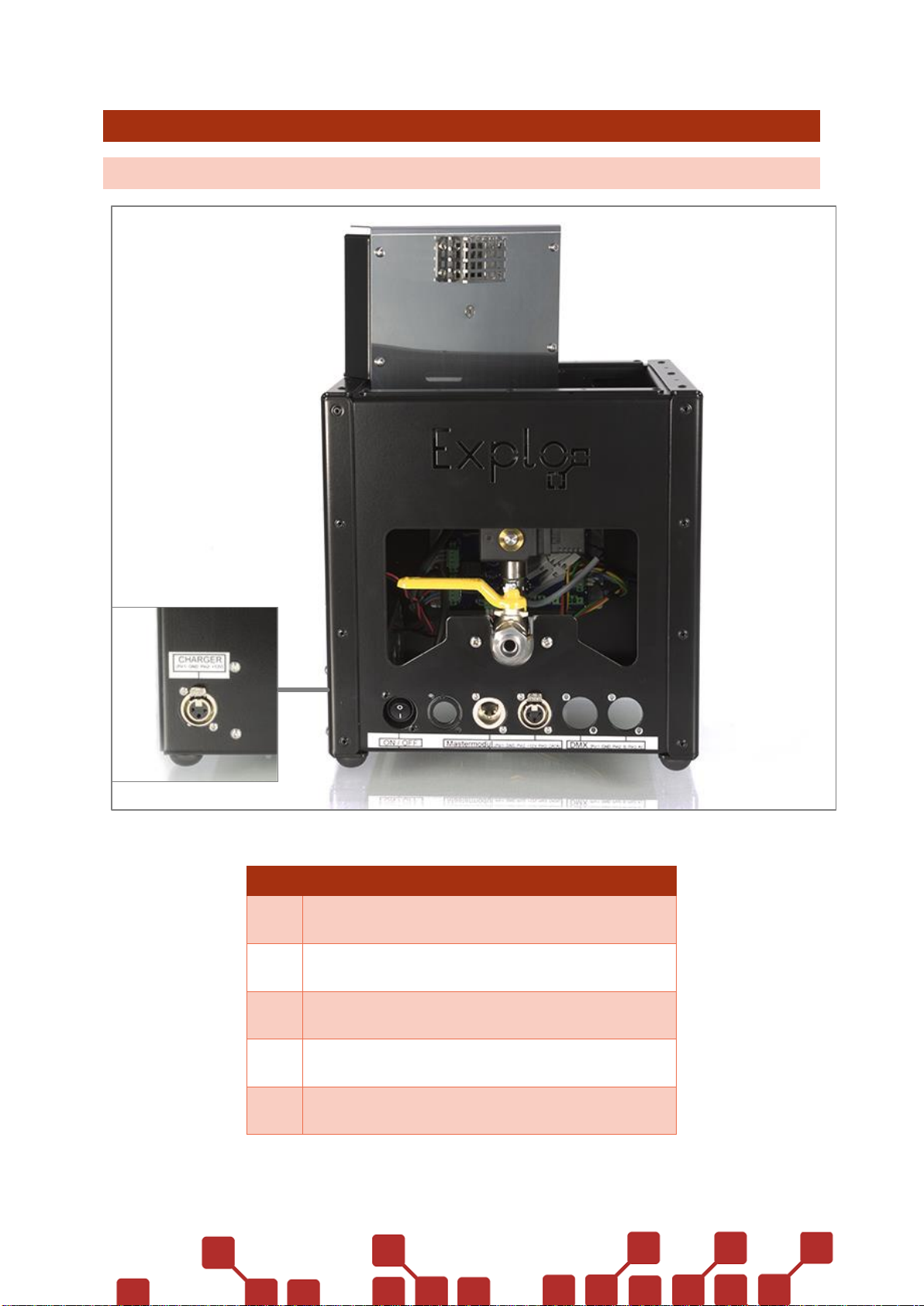
2.2 Components of the GX2 230V....................................................................................................... 8
2.2.1 Description of components...................................................................................................... 9
3 Usage of the Gasprojectors GX2 ....................................................................................................... 14
3.1 Planning the Show....................................................................................................................... 14
3.2 Preparing the devices for the show ............................................................................................. 14
3.3 Usage and positioning of gas bottles........................................................................................... 14
3.4 Connecting the gas bottles .......................................................................................................... 15
3.5 Switching the device on (only GX2 12V) ..................................................................................... 15
3.6 Controlling the GX2 230V............................................................................................................ 16
3.7 Controlling the GX2 12V.............................................................................................................. 16
3.8 Switching off the device (only GX2 12V) ..................................................................................... 17
3.9 Dismantling the setup .................................................................................................................. 17
3.10 Storing the system..................................................................................................................... 17
3.11 Taking care of your devices....................................................................................................... 18
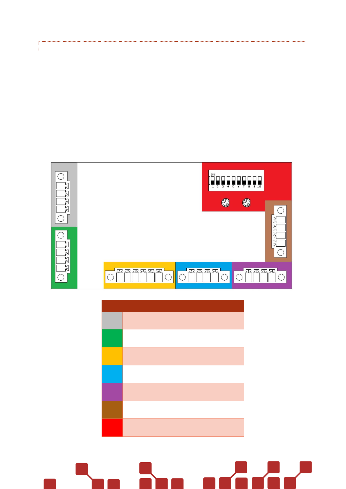
4 Description of the dip switch............................................................................................................... 19
5 Dipschalter.......................................................................................................................................... 19
5.1 Explanation of dip switches 1-8 ................................................................................................... 20
5.1.1 In Mastermodule-mode ......................................................................................................... 20
5.1.2 In DMX-Mode........................................................................................................................ 21
5.2 Description of Dip switch 9........................................................................................................... 23
5.2.1 1-channel-mode (switch set to on)........................................................................................ 23
5.2.2 2-cannel-mode (switch set to off).......................................................................................... 23
5.3 Description of switch 10............................................................................................................... 23
6 DMX-Mode.......................................................................................................................................... 23

6.1 Generally...................................................................................................................................... 23
6.2 Igniting via DMX........................................................................................................................... 23
6.3 Optical display.............................................................................................................................. 25
6.4 Example DMX-Mode.................................................................................................................... 25
6.4.1 1. Setting the dip switches .................................................................................................... 25
6.4.2 2. Connecting single components......................................................................................... 26
6.4.3 3. Control............................................................................................................................... 27
7 Alternative Built: The GX2 liquid......................................................................................................... 28
8 General safety notes .......................................................................................................................... 29
9 Recommended safety distances ........................................................................................................ 29
10 Technical Data.................................................................................................................................. 30

1 ABOUT THE GASPROJECTOR GX2
1.1 FUNCTION OF THE GASPROJECTORS
The Gasprojector GX2 is an effect device for the creation of straight flame effects of up to 6m height.
The GX2 uses Propane/Buthane bottles as a fuel supply, and can also be used with Aerosolee cans
by usage of the additional accessory "Aerosolee adapter". Another option is the upgrade of the
Projector for use with liquid fuels. In this case, the GX2 is modified in a way that it can access an
external pumping station with fuels like Bioethanol, ISOPAR or Isopropylalcohol.
Regardless of the control variant, the Gasprojector always uses a solenoid valve to control the Gas or
fluid regulation, as well as an electrical high voltage spark for ignition
1.2 FIELDS OF USE AND POSSIBILITIES
The gasprojector can be used Indoors, as well as outdoors. Its field of use are concerts, stage shows,
special effects for theaters and sport events, simple fire shows of fire artists, or as an effect in
conjuction with basic fireworks or Wave-Flamers.
Via DMX or special small receivers, the Gasprojector can also be integrated into automated shows.
This allows for a musical synchronized use of the Gasprojectors.
The usage of different nozzles and fuels influences the effect height and the setting of the effect time
can change the form of the effect (Flame ball or fire pillar).

2 DESCRIPTION OF THE GASPROJECTORS
2.1 COMPONENTS OF THE GX2 12V
Components of the GX2 12V
1
Electrical ignition
2
Solenoid valve and controller circuitry
3
Connector for gas hose and stopcock
4
Data socket and On/Off switch
5
Charging socket and Lead acid battery
1
2
1
3
4
2
5

2.2 COMPONENTS OF THE GX2 230V
Components of the GX2 230V
1
Electrical ignition
2
Solenoid valve
3
Connector for gas hose and stopcock
4
Controlling cable
2
3
5
1
4

2.2.1 DESCRIPTION OF COMPONENTS
2.2.1.1 ELECTRICAL IGNITION
The electrical ignition consists of an ignition coil and two electrodes, between which the spark used to
ignite the gas is being made. On the GX2 230V the ignition coil is activated directly via the 230V power
cable, whereas on the GX2 12V the ignition is controlled via the integrated circuitry.
The spark made at the ignition electrodes is a life hazard. Even though it is covered with a grate, you
should not touch any parts near it once the gasprojector is activated.
2.2.1.2 SOLENOID VALVE
In the case of the Gasprojector you can find a solenoid valve, and in the case of the GX2 12V also the
controller cicuitry. The solenoid valve is used to regulate the gas flow and is activated via the 230V
power supply on the GX2 230V, or the coltroller circuitry on the GX2 12V.
2.2.1.3 CONNECTOR FOR THE GAS HOSE AND THE STOPCOCK
The front of the GX2 features the connector for the gas hose, as well as the stopcock to stop the gas.
The gas connector is a 10L threading.
The optionally available Aerosolee adapters for gas cans can also be fixed to this mount.
If the stopcock is in a 90° angle, the pipe is closed. If it parallel to the piping, it is open. Never store
the gasprojector with a closed stopcock, since rest gas can damage the internal sealings
2.2.1.4 CONTROLLER CABLE (GX2 230V)
The Gasprojector GX2 230V features a standard 3m cable with a two-pin grounded plug (CEE 7/7). It
is used to connect the GX2 230V to the needed supply of 230V. A slong as the voltage is given, the
gasprojector will ignite.
Alternative
Instead of the integrated cable, PowerCon-connectors (In and Out) can be built into
the Gasprojector.

2.2.1.5 CONTROLLER CIRCUITRY
The integrated electronic of the GX2 12V uses any ignition signals coming from outside and transmits
and ignition or other commands to the ignition coil and the solenoid valve. A built in dip switch allows
you to set a DMX channel (1-255) in DMX mode, or setting a standardized opening time for use with
an RX-1K Gas.
The controller circuitry also features a connector for the external ignition via 9-80VDC. It is normally
built as a twin pole cable. If the GX2 is fitted with an RX-1K Gas, this cable is no longer built into older
models.
The connector clamps can be dismounted from their sockets with the two cross headed screws on
either side. If you should wish to remove the internal circuitry, for example to make an update, please
only unscrew the connector terminal blocks from their sockets, and not every single cable. The
electronic can be dismounted by loosening the two Inbus screws on the back side of the Gasprojector.
Connectors on the controller circuitry
Ignition coil
Charging socket, battery, On/Off switch
Mastermodul
DMX
RX2-1K Gas
External ignition, solenoid valve
Status-LEDs, Dip switches

2.2.1.6 DATA SOCKETS AND ON/OFF SWITCH (GX2 12V)
The front of the Gx2 12V features the data sockets, as well as the On/Off switch. The GX2 12V van be
controlled via the data sockets. It is standard fit with connectors for the radio receiver RX-
Mastermodule (In and Out). Optionally, it can also be fitted with connectors for the DMX protocoll, or a
connector for the receiver RX-1K Gas. The following standard fits are available for the GX2 12V:
The pins of the data sockets have the following layout::
Pin 1
Pin 2
Pin 3
Pin 4
Mastermodule
GND
+12VDC
DATA
/
DMX
GND
B
A
/
RX-1K
GND
+12VDC
IGNITION -
IGNITION +

2.2.1.7 CHARGING SOCKET AND LEAD ACID BATTERY (GX2 12V)
The GX2 12V is fitted with a separate charging socket on the left side of the device, to which a fitting
charger can be mounted (we recommend an Optimate charger). The charger is not standard supplied
with the GX2.
The pin layout is as follows:
Pin 1
Pin 2
Pin 3
Charging socket
GND
+12VDC
/
As a power supply for the GX2 12V a standard 12VDC lead acid battery
(2.200mAh) is used. It is fit to the inside of the device with a mounting bracket and
is charged via the aforementioned charging socket. The battery should be recharged before and after
each show, as well as every 2 months when stored for a longer time., since it could lead to deep
discharge otherwise, which damages the battery-
If needed, a second lead acid battery can be fit to the other side of the Gasprojector.
Alternative
Instead of the built in lead acid battery, a mains supply (230VAC to 12VDC, class
IP67) can be built in. In this case, two PowerCon connectors (In and Out) would be fit
to the fron panel which supply the mains supply.
2.2.1.8 GAS NOZZLE
On the head of the Gasprojector, underneath the ignition, a gas nozzle can be found, through which
gas is ejected during ignition.
When selecting a nozzle, one must make a distinction between using one for Aerosolee cans or gas
bottles. Further you must decide between liquid or gaseous gas. Gaseous gas use occurs when you
are using your gas bottle right side up. Liquid gas use is made when the bottle is flipped onto its head.
Generally it can be said that during liquid use, higher flame effects can be achieved, but the fuel
consumption is also heightened. Also, dirt can collect on the bottom of the bottle, which can block the
nozzles during liquid use.
A detailled description of the different nozzles can be found on the next page (Note: Only the two
Outdoor nozzles are standardly supplied with the gasprojector).

Product
Gas
usage
Flame height
Maximum shots
Flame look
Gas nozzle,
gaseous
With or without reduction
Propane/Buthane
gaseous
3m
180 Shots / 1sec Opening time
280 Shots / 100ms Opening time
Fire balls and Flame pillars
Propane/Buthane
liquid
not possible
-
-
Aerosole
gaseous
1m
140 Shots / 100ms Opening time
(nur bei 100ms verwenden)
Short, small Fire balls and Flame
pillars
Aerosole liquid
not possible
-
-
Gas nozzle, liquid
With or without reduction
Propane/Buthane
gaseous
not possible
-
-
Propane/Buthane
liquid
6m
70 Shots / 1sec Opening time
160 Shots / 100ms Opening time
Fire balls and broader Pillars
Aerosole
gaseous
not possible
-
-
Aerosole liquid
5m
27 Shots / 1sec Opening time
70 Shots / 100ms Opening time
Fire balls and broader Pillars,
longer Shots not possible
Aerosol nozzle
With reduction
Propane/Buthane
gaseous
not possible
-
-
Propane/Buthane
liquid
3m
270 Shots / 1sec Opening time
800 Shots / 100ms Opening time
Thin flame pillar (for indoor use)
Aerosole
gaseous
not possible
-
-
Aerosole liquid
3m
27 Shots / 1sec Opening time
70 Shots / 100ms Opening time
Thin flame pillar (for indoor use)
Reduction
The reduction prevents an afterburn at the nozzle and can be obtained for every nozzle type. Please
contact the manufacturer for further informations about the upgrade with reductions.
***The data supplied above is meant for a 10Kg gas bottle (Propane/Buthane mix), or two aerosole cans with 330g each, 20°C outer temperature and no wind. Wind and cold can
affect flame height and look strongly***

3 USAGE OF THE GASPROJECTORS GX2
3.1 PLANNING THE SHOW
A successful show begins with careful planning. We recommend taking note of these factors:
Checklist for planning
Are Gasprojectors allowed at the location?
Can the needed safety distances be kept?
How many gasprojectors do I wish to use?
What flame height do I wish to use? (selecting a nozzle!)
Optional: Do I want to use aerosole cans or a gas bottle?
Optional: Planning the automated show (only when controlling via radio).
3.2 PREPARING THE DEVICES FOR THE SHOW
Nothing is more maddening than a gasprojectors whose battery is already empty before the show, or if
the gas hose has been forgotten at the storage facility. So these items should be checked before
driving to the show:
Checklist before the show
Do I have all the gasprojectors needed with me?
Do I have the right nozzles?
Do I have enough gas hoses / Aersosole adapters?
Are the batteries of my gasprojectors charged?
Do I have a spare charger / spare battery with me?
Are the ignition electrodes cleaned?
Do I need further accessories? (Tripod, socket wrench, connector cables?)
Do I have the necessary controllers with me and programmed?
Optional: Do I have the external pumping station? (only with GX2 liquid)
If the above questions can be answered with YES, you are one step closer to a successful show.
3.3 USAGE AND POSITIONING OF GAS BOTTLES
The general safety guidelines for the usage with gas, as well as the instructions on the safety
datasheet of the used gas are to be adhered. Generally propane is heavier than air, so it should not be
used in unventilated areas, ground indents (deeper than 20cm) or near waste pipes. Especially near
cellars, an ignitable gas-air mixture can appear. Only use CO² extinguishers to extinguish flames.
The gasprojector may only be used in ventilated rooms. For the saftey distances, the following is true:

15
Generally, the gasprojector must have enough distance to all living beings and objects, so that they
may not be harmed or endangered using the device. The manufacturer recommends 3 meters in a
radius, and 8 meters in height to all objects and persons (standard GX2 variant, outdoor nozzle liquid).
However, please adhere to the safety distances as laid out by the local fire department. Please take
note of wind direction when setting up your devices.
For positioning, it is recommended to have the connectors not face the audience.
3.4 CONNECTING THE GAS BOTTLES
The gas bottles must be placed on firm, even ground, and be proofed against accidental tipping. The
gas hose should be connected to the gasprojector first, and then the gas bottle. Before connecting to
the gas bottle, make sure the stopcock of the projector is closed.
It is recommended to test for leak tightness, using a leak tightness spray.
The gas bottle connector is a Euro-connector with 30mm wrench width. Note that the gas connector
has a left threading. Up to 3 gasprojectors can be connected via T-adapters to a single bottle. Should
you have more than 3 gasprojectors in use, you must use further gasbottles
Alternative
When using aerosole adapters, the adapter must first be mounted to the device. Then
the aerosole cans can be mounted to the adapter with the valves closed.
3.5 SWITCHING THE DEVICE ON (ONLY GX2 12V)
The device can be switched on via the Wipp-switch on the front of the GX2. Put the switch into the "I"
position. Using the Status-LEDs you can see if the device has been switched on.
Red LED when switching on (Status of the internal battery)
3x flashing
Battery fully charged
2x flashing
Battery weak
1x flashing
Battery must be charged

16
Green LED after switching the device on
Steady light
Shows that the projector is
activated.
3.6 CONTROLLING THE GX2 230V
Control of the GX2 230V is exclusively made via supllying the device with a voltage of 230VDC with
the two-pin grounded plug. Simply put: Plug connected to socket > device ignited, plug disconnected >
device doesn't ignite.
The gasprojector will ignite for as long as it is supplied with sufficient voltage. Setting the opening time
at the device itself is not possible. For a controlled ignition, it is recommended to get a switch box, a
DMX Switch Pack (not a Dimmerpack!) or anything close to that.
Important: Steady use (a continuous flame) can damage the GX2 230V. It is recommended to not
leave it active for more that 5 or 6 seconds, with a 2 second pause in between (short bursts are
however continuously possible).
3.7 CONTROLLING THE GX2 12V
Control of the GX2 12V can be made with 4 different options:
1.) Control via the RX-Mastermodule (Radio variant)
→ see manual of the RX2-Mastermodule
2.) Control via the RX2-1K Gas (Radio variant)
→ see manual of the RX2-1K Gas

17
3.) Control via an external ignition trigger
This allwos you to ignite the gasprojector by use of an external trigger on the twin pole cable. As long
the trigger is made on the cable, the effect will ignite. The opening time can be set on the dip switches.
Further informations can be found in the description of the dip switches.
An ignition trigger must be between 9 - 80 VDC (eg. Ignition of an EXPLO receiver. For the trigger,
polarity need not be cared for).
4.) Control via DMX (optional)
→ see Chapter DMX-Mode
3.8 SWITCHING OFF THE DEVICE (ONLY GX2 12V)
To switch off the device, set the wipp switch to the "O" position. Check if the device is switched off by
use of the Status-LEDs.
3.9 DISMANTLING THE SETUP
After usage of the system, first close the valve at the gas bottle or the aerosole cans. Then air out the
hose or the adapter and the gasprojector, by igniting it until no flame appears. After airing it, the
gasbottle or cans can be disconnected, and the gas hose or adapter from the gasprojector. Never
transport gasprojectors under pressure, since this carries a high risk to you, as well as it might
damage the gasprojector.
3.10 STORING THE SYSTEM
Store gas bottles according to the law. the manufacturer of your gas bottles can tell you more about
this.
The gasprojectors should be stored at room temperature ideally. Never store them uder pressure (rest
gas). This not only poses a high security risk, but it might also damage the seals of the device.

18
Should you use a gasprojector GX2 12V with integrated battery, charge it before and after every show,
as well as every 2 months during storage. Lead acid batteries discharge during storage by
themselves, which can lead to a damage of the battery, if not prevented with regular charging.
Clean your devices before storage.
3.11 TAKING CARE OF YOUR DEVICES
The devices should be cleaned after a show. Simply remove dirt and dry out the devices. The use of
pressurized air is recommended.
If the ignition electrodes are very dirty, carefully clean them with a wire brush. Disconnect the device
from any sort of power supply for this.
Aditionally, you can remove coilings and plungers from the solenoid valve, and clean the inner tubings
of the valve with pressurized air. Even though there is an internal sieve, dirt from the gas bottle can be
accumulated here.

19
4 DESCRIPTION OF THE DIP SWITCH
The integrated 10 step dip switch allows you to change different settings, such as the DMX channel or
the opening time during mastermodule usage, before using the gasprojector.
5 DIPSCHALTER
The dip swith has 10 single switches (see picture above). The switches 1-8 (from left) allow you to set
the opening time in mastermodule mode, or the DMX channel in DMX mode. Switch 9 is used to
change between 1 channel DMX mode (only ignition channel) to 2 channel DMX mode (ignition and
safety channel). Switch 10 allows you to select between DMX or mastermodule mode.
Switch 1
Switch 2
Switch 3
Switch 4
Switch 5
Switch 6
Switch 7
Switch 8
Value if
„ON“
1
2
4
8
16
32
64
128
Value if
„OFF“
0
0
0
0
0
0
0
0
Switch is up: "ON"
Switch is down: "OFF"
„ON“: DMX- Mode
„OFF“: Mastermodul- Mode
(only in DMX-Mode):
„ON“: 1-channel-mode
„OFF“: 2-channel-mode

20
5.1 EXPLANATION OF DIP SWITCHES 1-8
Each of the 8 switched has its own (according to the binary system) value (see table below), which is
added of the switch is set to "ON" (switch is in the upper position). The sum of all 8 switch values gives
you the opening time, or the DMX channel.
5.1.1 IN MASTERMODULE-MODE
In Mastermodule mode, the switches 1-8 are used to set the opening time of the external igition.
Switch
Opening time (ms)
1
20
2
40
3
80
4
160
5
320
6
640
7
1280
8
2560
Example for the opening time:
An opening time of 400ms should be used. It is made by adding the values of 80+320 = 400. These
values are given to the switches 3 (opening time 80ms) and 5 (opening time 320ms).
Therefore, to create an opening time of 400ms the switches 3 and 5 must be set to "ON" and all
others to "OFF".
This manual suits for next models
2
Table of contents
Other Explo Dj Equipment manuals