Explo X2 Wave Flamer User manual

2
PREAMBLE
Dear Explo customer,
Please read through these instructions carefully before using the devices. It contains many
informations which will help you in getting to know your system.
Reading through this manual will support you in a
responsible use of this product.
We ask you to follow the safety- and usage tips provided by us.
Should you have any questions, or should there be any unclarities, which this manual cannot answer,
please do not hesitate to contact us vie E-Mail or by phone.
We hope you'll have fun with your new ignition system,
Your Explo Team

3
INDEX
1 Overview of the X2 Wave Flamer......................................................................................................... 5
1.1 Function of the Wave Flamer......................................................................................................... 5
1.2 Areas of usage and possibilities .................................................................................................... 5
2 Receipt of goods................................................................................................................................... 5
3 Components of the X2 Wave Flamer................................................................................................... 6
3.1 Standard-Variant (Front)................................................................................................................ 6
3.2 Standard variant (TOP).................................................................................................................. 7
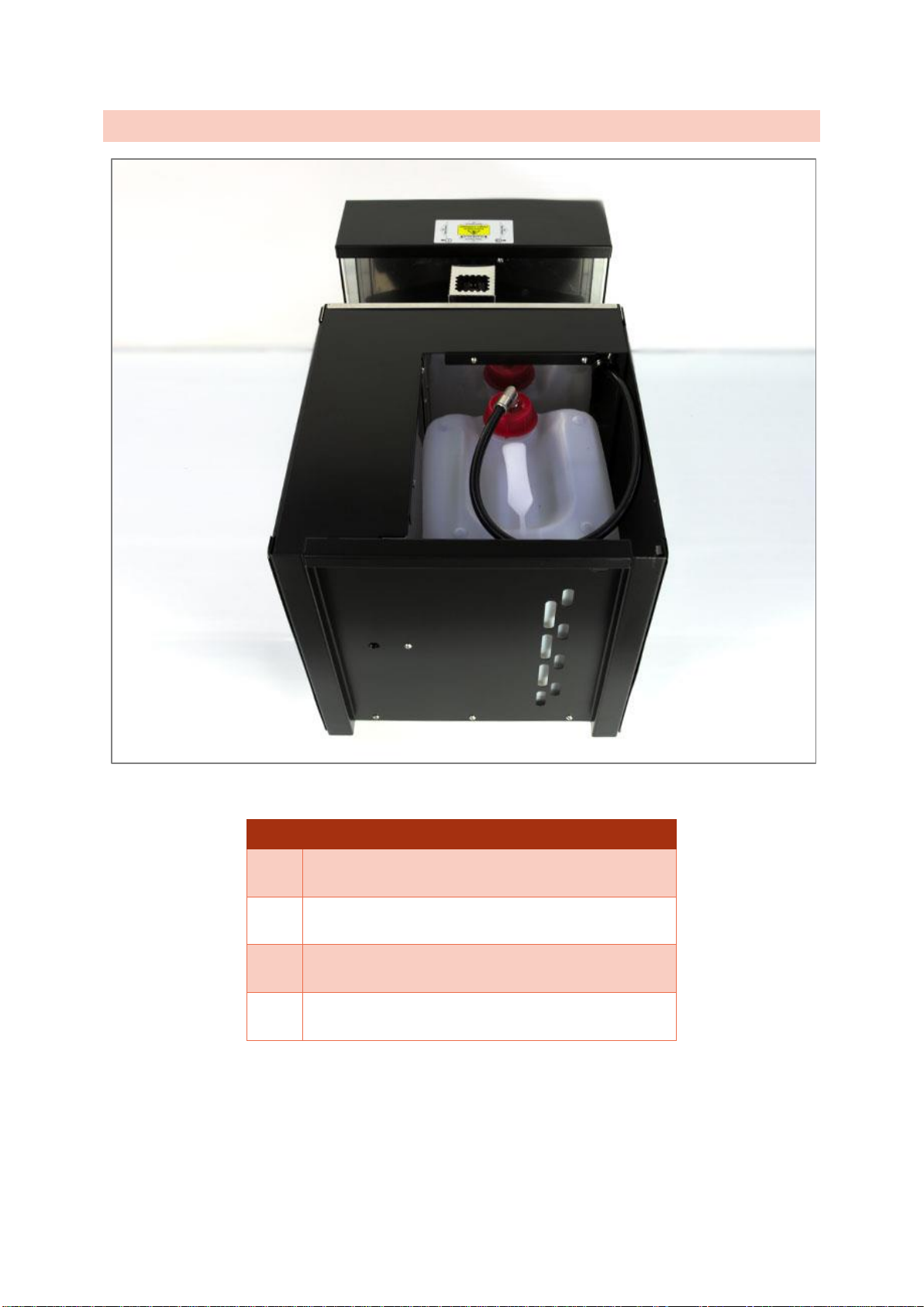
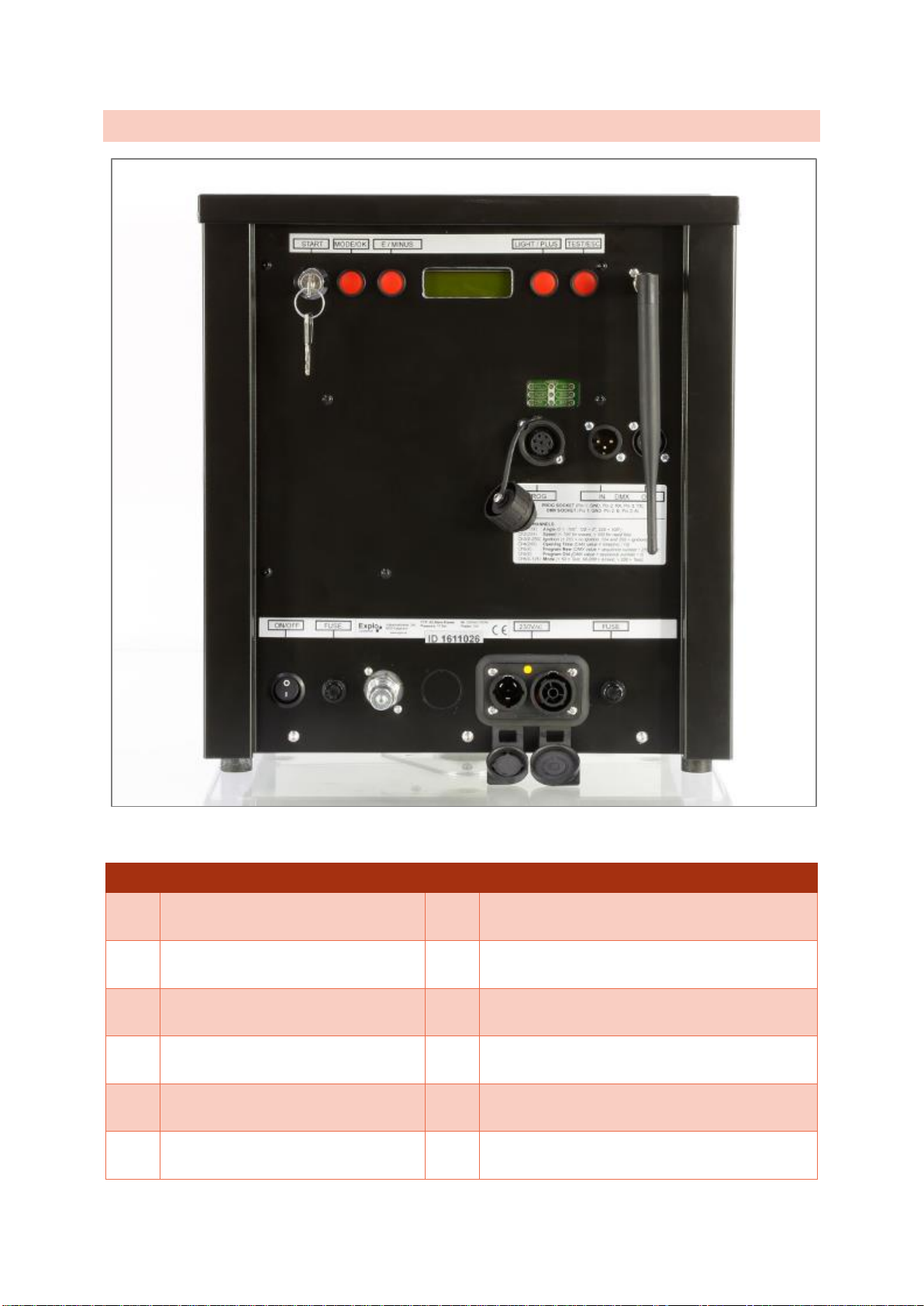
3.3 Head Variant without internal pumping unit (Front)....................................................................... 8
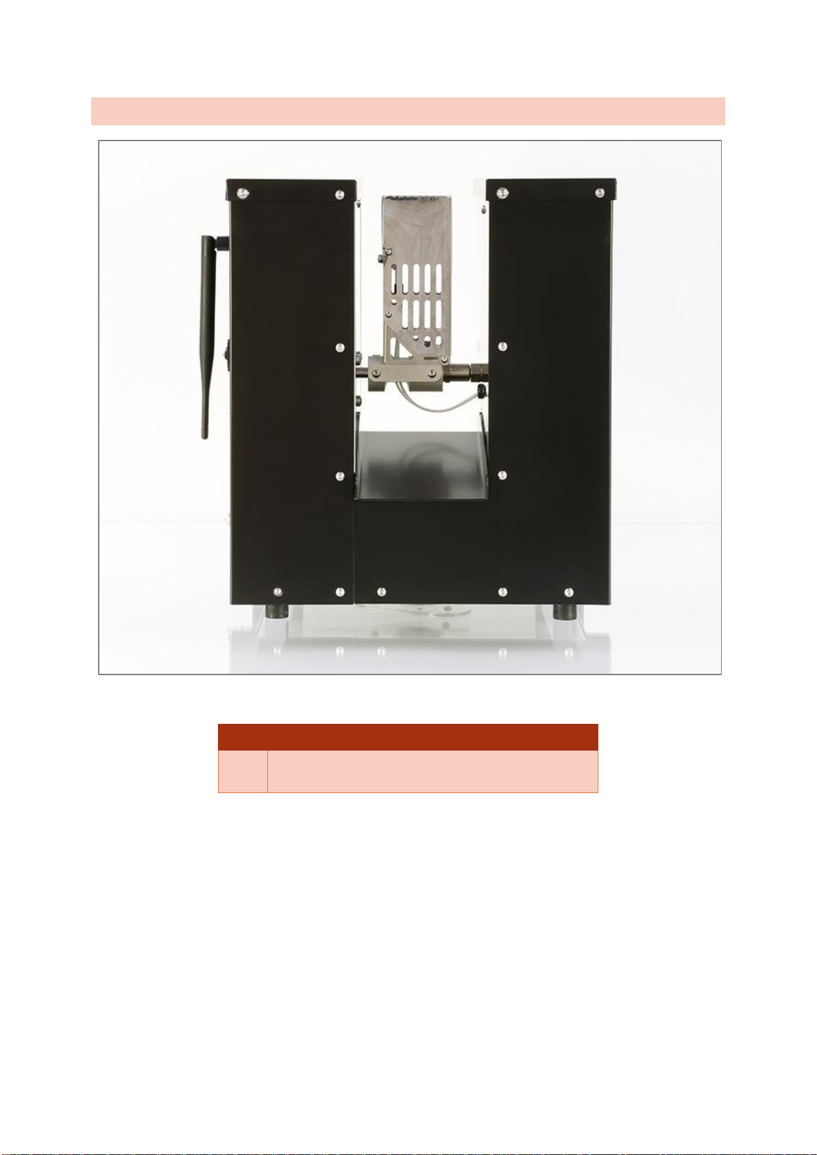
3.4 Head Variant without internal pumping unit (Side) ........................................................................ 9
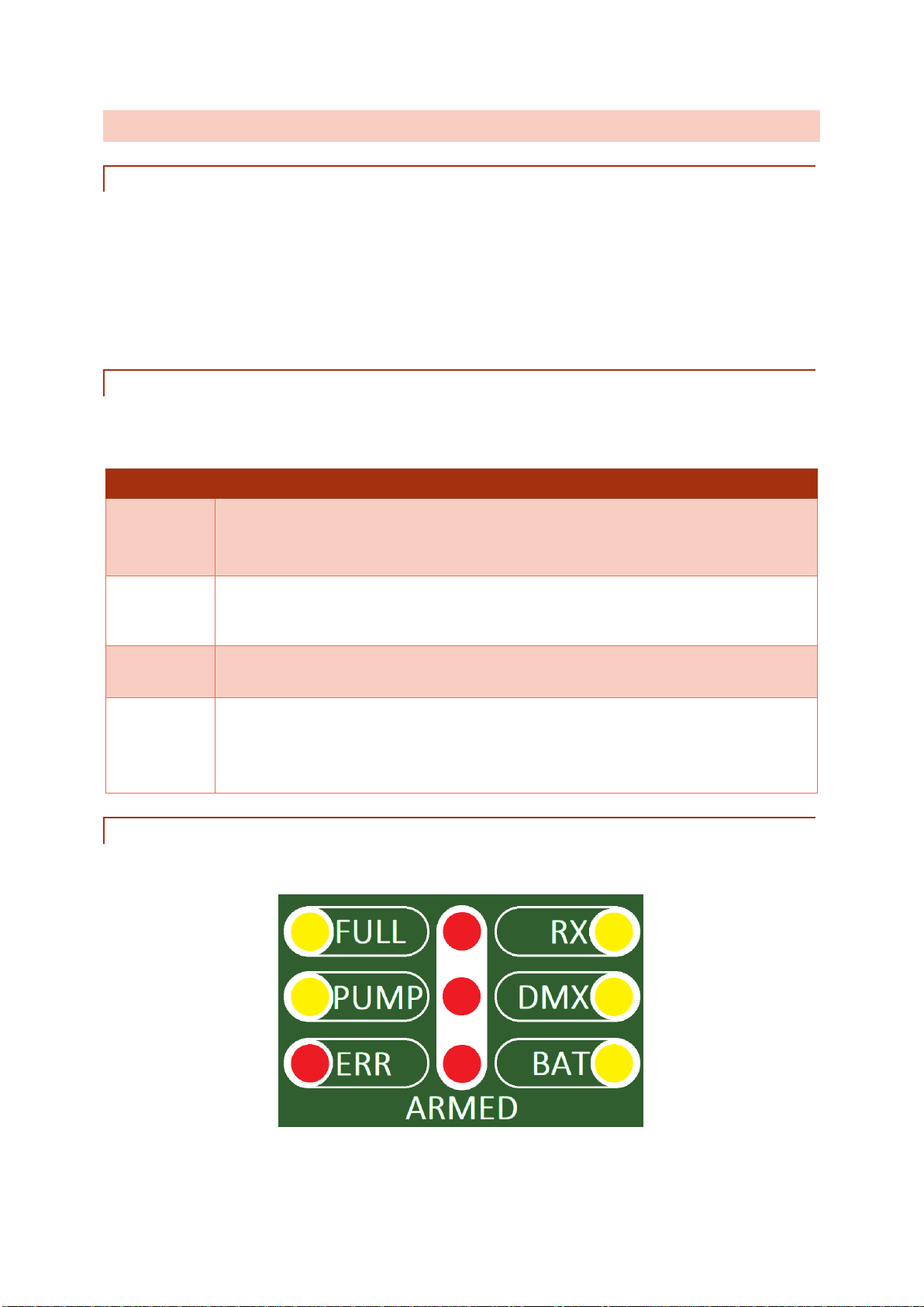
3.5 Description of Components ......................................................................................................... 10
4 Menu items......................................................................................................................................... 13
4.1 Main menu ................................................................................................................................... 13
4.2 Wave Flamer Settings.................................................................................................................. 18
4.3 DMX-Settings............................................................................................................................... 23
5 General, Definitions............................................................................................................................ 24
5.1 Definition audience side............................................................................................................... 24
5.2 Definition Positions ...................................................................................................................... 25
6 Planning an preparing a show............................................................................................................ 25
7 Positioning and preparation at the show location............................................................................... 26
7.1 Positioning of the devices............................................................................................................ 26
7.2 Power supply ............................................................................................................................... 26
7.3 Preparing for the show................................................................................................................. 27
8 Controling the X2 Wave Flamers - Generals...................................................................................... 27
8.1 Activation...................................................................................................................................... 27
8.2 Switching off................................................................................................................................. 27
9 Manual control via radio ..................................................................................................................... 28
9.1 Preparing the manual ignition mode............................................................................................ 28
10 Automatic control via radio (AutoShow)........................................................................................... 29
10.1 Preparing the automatic ignition mode (AutoShow) .................................................................. 29

4
10.2 Preparing the ShowCreator Software........................................................................................ 29
10.3 Setting ignition cues................................................................................................................... 31
10.4 Selecting an effect ..................................................................................................................... 32
10.5 Group boxes .............................................................................................................................. 33
10.6 Designating and using groups in the ShowCreator ................................................................... 34
10.7 Setting an opening time............................................................................................................. 39
10.8 Calculating the drive time........................................................................................................... 41
10.9 Transferring the show to your devices....................................................................................... 41
11 Control via DMX 512 ........................................................................................................................ 41
11.1 Preparing the DMX-512-Mode................................................................................................... 42
11.2 DMX-channels ........................................................................................................................... 42
11.3 Igniting via DMX......................................................................................................................... 46
12 Control via Easy-DMX ...................................................................................................................... 46
12.1 Preparing the Easy-DMX-Mode................................................................................................. 46
12.2 DMX-channels ........................................................................................................................... 47
13 Safety................................................................................................................................................ 48
13.1 Angle blockers ........................................................................................................................... 48
13.2 Safety features........................................................................................................................... 49
13.3 Safety recommendation............................................................................................................. 50
13.4 Safety hints ................................................................................................................................ 50
13.5 Recommended safety distances................................................................................................ 51
14 Storage and maintenance ................................................................................................................ 52
15 Technical data .................................................................................................................................. 53
16 Accessories (available separately)................................................................................................... 53
17 Informations for useable fluids ......................................................................................................... 53
18 Software updates.............................................................................................................................. 54

5
1 OVERVIEW OF THE X2 WAVE FLAMER
1.1 FUNCTION OF THE WAVE FLAMER
The flame projector X2 Wave Flamer is an effect device, used to create a moving flame effect of up to
10m height, and a vertical swivel radius of 210°.
The X2 Wave Flamer uses liquid fuels, like ISOPAR, Bioethanol or Isopropylalcohol, which are stored
in an internal canister, and sucked into the system by an integrated pumping unit. A motorized swivel
head ejects the fluid into the preferred direction.
The X2 Wave Flamer uses two solenoid valves to control the liquids flow, as well as an electrical high
voltage spark to ignite the fuel.
1.2 AREAS OF USAGE AND POSSIBILITIES
The X2 Wave Flamer is suitable for indoor and outdoor shows. Its usages can vary from concerts and
stage shows, to special effects for theatre productions and sports events (eg. Entering of the players
during football or ice hockey), pure fire shows by fire artists, or in conjunction with regular fireworks.
Via DMX, or the explo radio control, the projector can be integrated into automated shows. This allows
for a musical synchronous usage of the device.
The choice of different nozzles affects the effect height and different fluids the colouring of the flame
effect.
2 RECEIPT OF GOODS
In rare cases, problems might occur due to damages from transport, so we ask you to check the
goods for the following after receipt:
Checklist when getting your goods
Is the package damaged outside? (Take pictures!)
Are the goods damaged outside?
Are the goods fully functional?
Are all accessories delivered? (Antenna and power cable are in the back with
the canister)
We would ask you to notify us of damages or missing articles. Retroactive reclamations cannot be
taken into consideration unfortunately.

6
3 COMPONENTS OF THE X2 WAVE FLAMER
3.1 STANDARD-VARIANT (FRONT)
Components of the X2 Wave Flamer
1
Key switch
6
DMX-Connectors
2
Display and usage buttons
7
ON/OFF switch (Power)
3
Status-LEDs
8
Fuze 12VDC
4
Antenna socket
9
Power connector
5
Programming socket
10
Fuze 230VAC
1
2
9
8
7
3
5
10
4
6

7
3.2 STANDARD VARIANT (TOP)
Components of the X2 Wave Flamer
1
Swivel head and electrical ignition
2
Internal 10L fluid canister
3
Lead through for external fluid canister
4
Level indicator
2
3
1
4

8
3.3 HEAD VARIANT WITHOUT INTERNAL PUMPING UNIT (FRONT)
Components of the X2 Wave Flamer
1
Key switch
7
ON/OFF switch (Power)
2
Display and usage buttons
8
Fuze 12VDC
3
Status-LEDs
9
Connector for external pumping unit
4
Antenna socket
10
Power connector 100-230VAC Neutrik True-1
5
Programming socket
11
Fuze 230VAC
6
DMX-connector
1
2
9
8
7
3
5
10
4
6
11

9
3.4 HEAD VARIANT WITHOUT INTERNAL PUMPING UNIT (SIDE)
Components of the X2 Wave Flamer
1
Swivel head and electrical ignition
1

10
3.5 DESCRIPTION OF COMPONENTS
3.5.1 KEY SWITCH
After switching on the power supply with the wip-switch (7), the projector can be activated. To activate
the device, only short impulse via the key switch is needed. It can be turned off after activation. The
Wave Flamer will remain switched on regardless.
This has an important function during a show in case of a power outage. If the key switch is in the ON
position, the device will start up automatically after losing power. If it is switched off however, the
device will remain powered off too after getting the power back.
3.5.2 DISPLAY AND USAGE BUTTONS
Via the display and the usage buttons, the most important values of the Wave Flamer can be seen,
and the menu be navigated through. Outside of the Menu, some buttons have special functions.
Usage buttons of the X2 Wave Flamers
Mode / OK
Outside the menu, this button is used to access the menu.
Inside the menu, this button is used to confirm.
If held during startup of the Wave Flamer: Wave Flamer will start in radio mode.
E / Minus
Outside the menu this button is used to de-pump. If the device is armed, it will be
switched into test mode too.
Inside the menu this button functions as a minus button.
Light / Plus
Outside the menu you can use this button toggle the background light on and off.
Inside the menu it can be used as a plus button.
Test / ESC
Outside the menu this button can be used to send a test signal to the transmitter, to
check radio connection (only in test mode).
Inside the menu can be used as an escape button.
If held during startup: Wave Flamer starts in DMX-Mode.
3.5.3 STATUS-LEDS
Via the Status LEDs, different states of the Wave Flamer can be checked.

11
Status-LEDs of the X2 Wave Flamer
FULL
Shows that the pumping unit has reached usage pressure.
PUMP
Is only lit if the pump is working. Should only be lit in armed-mode.
ERR
This LED indicates any errors with the device. If lit, the fuel canister may be empty.
The Wave Flamer may not be used if this LED is lit, since it may lead to damages of
the device.
Please note the errorcode and contact the manufacturer.
RX
This LED flashes if a radio signal from the transmitter is received.
DMX
If DMX is integrated into the device, and is ready for use, this LED will be lit. If the
projector receives DMX signals, it will flash for confirmation.
BAT
Shows the status of the power supply. If it is lit permanently, the power is okay. If it
begins to flash, the device does not receive sufficient power. This may be caused by
a defunct mains supply.
ARMED
The three middle LEDs are lit if the device is in armed-mode. During this time, be
cautious when using the device, and make sure all safety distances are being
adhered to.
3.5.4 ANTENNA SOCKET
A fitting antenna with BNC connector can be mounted to the BNC antenna socket for radio use. We
recommend the use of original antennas.
The antenna is used to receive data. Pinching or breaking the antenna or its cable can lead to
damages, and should therefore be avoided. During use, make sure that the antenna is safely mounted
and placed upright, to guarantee the best possible radio reception.
Water or moisture entering the antenna socket can drastically decrease the radio reception.
3.5.5 PROGRAMMING SOCKET
Combined with the bootloader programming cable (sold separately) updates of the devices software
can be made by yourself.
3.5.6 DMX-CONNECTORS
Via the 3 pole XLR connectors, a DMX controller can be connected to the Wave Flame. The outgoing
socket can be used to forward the DMX signal to the next Wave Flamer.
Pin-configuration of the DMX-connector
Pin 1
GND
Pin 2
B
Pin 3
A
3.5.7 ON / OFF SWITCH (POWER)
Allows you to switch the Wave Flamers power supply on or off. After switching the wip switch on, the
key switch must be at least switched on shortly, to start up the device.

12
3.5.8 FUZE 12VDC
10A delay action fuze for the internal 12VDC power supply.
3.5.9 POWER CONNECTOR
Allows you to connect the power supply of the Wave Flamer. The internal mains supplies are meant
for 110VAC to 230VAC.
3.5.10 FUZE 230VAC
10A delay action fuze for the 230VAC power supply.
3.5.11 SWIVEL HEAD AND ELECTRICAL IGNITION
Here you can find the motorized swivel head of the Wave Flamer, as well as the socket for the nozzle
and the electrodes for the electrical ignition.
3.5.12 INTERNAL 10L FLUID CANISTER
Only found in the standard variant. Here you can find the internal, reusable canister for liquid fuels.
The maximum liquid capacity is 10 Liters.
3.5.13 LEAD THROUGH FOR EXTERNAL FLUID CANISTER
Only found in the standard variant. An extension hose (sold separately) can be lead through this
opening and be attached to an external fluid tank.
3.5.14 LEVEL INDICATOR
Only found in the standard variant.Allows you to gauge the fuel level of the internal canister.
3.5.15 CONNECTOR FOR EXTERNAL PUMPING UNIT
Only found in the head variant without internal pumping unit. This special variant of the Wave Flamer,
without internal canister and pumping unit, allows you to connect an external pumping unit via a fitting
hose to the quick coupling at the front panel.
The maximum use pressure should not be higher than 14 bars.

13
4 MENU ITEMS
The menu of the Wave Flamer can be opened in test-mode with the Mode/OK button. The navigation
through the menu is done with the Plus and Minus button. The Mode/OK button allows you to confirm.
Exiting the menu can be done with the Test/ESC button.
The menu will close automatically after a minute of inactivity.
4.1 MAIN MENU
Menu
ID and Box number
Pressure
Mains supply informations
Type and Showname
Check and Lines
Sec-Key and Frequency
Power and Timeout
Position min/max
View AUTOSHOW list
Edit Wave Flamer settings
see sub chapter
Edit DMX settings
see sub chapter
Systemtest start?
see sub chapter
Pump and vent
Software version
Group BOX

14
4.1.1 ID AND BOX NUMBER
Shows you the ID number (line 1) and the Box number (line 2) of the device.
4.1.2 PRESSURE
Shows the current pressure of the device in percent (line 1). Line 2 shows the time (in seconds) that
the device needs to build up maximum pressure, as well as the lowest value the pressure has reached
after getting to 100% (u97% means that the device has lost pressure to 97% after an ignition).
The letter at the end of the second line shows you if the pressure is set to Low (L), Medium (M), or
High (H). This feature is currently not in use. The normally used setting is Medium.
4.1.3 MAINS SUPPLY INFORMATIONS
Shows the power values of the mains supllies for the 12V supply (line 1), as well as the 24V supply
(line 2).
4.1.4 TYPE AND SHOWNAME
Shows you the type of the product as it will be listed in the device list of the transmitter (line 1), as well
as the name of the show currently saved on the device (line 2).
4.1.5 CHECK AND LINES
Shows you the Checksum of the device (line 1) and the number of ignition cues the current show has
for the device (line 2).

15
4.1.6 SEC-KEY AND FREQUENCY
Allows you to see the set Secure-Key (line 1) and the set frequency of the internal radio module (line
2).
4.1.7 POWER AND TIMEOUT
Here you can see the set radio power of the radio module (line 1) and the time after which the show
will stop if no transmitter signal is received (line 2).
4.1.8 POSITION MIN/MAX
Shows the minimum and maximum positions the projector will drive to. In addition to this software
solution, mechanical angle blockers are recommended. If such are used, the software must be set to
the blocked angles too however.
4.1.9 VIEW AUTOSHOW LIST
Shows all ignition lines used by the device, if an AutoShow has been created.
4.1.10 EDIT WAVE FLAMER SETTINGS
Here you can edit different settings of the projector. See the corresponding sub chapter.

16
4.1.11 EDIT DMX SETTINGS
Allows you to change the DMX settings of the projector. See corresponding sub chapter.
4.1.12 SYSTEMTEST
This menu item is used to start different internal system tests. They should only be made after being
instructed by qualified personnel.
Systemtest start?
Press PLUS for start Systemtest
Battery 12V
Battery 24V
Drivetest
Speedtest
MAG 3 Evacuate
pump signal
!! PUMP !!
!! EVACUATE !!
MAG 1 First
MAG 2 Second
IGNITE
Display + Leds
Taster + RADIO

17
4.1.13 PUMP AND VENT PUMP
Allows you to pump the system and eject fluid without ignition. It is mainly used to vent the internal
system (Especially in combination with the solenoid valves and nozzle). Alternatively, can be used for
a test run of the Wave Flamer.
When using Pump and Ventpump the Wave Flamer will pump and vent multiple times.Afterwards,
the fluid can be ejected manually (automatic 45° leftward sloping of the head).
4.1.14 SOFTWARE VERSION
Shows the current software of the device. A regular checking and updating of the software is highly
recommended. You can find further informations for this at the end of this manual.
4.1.15 GROUP BOX
Shows the set Group box numbers. With the Mode/OK button you can switch to the next two Group
box number.
This option can only be used for manual ignition signals or for control with the PC-mode (ShowPlayer
software) via box- and channelnumber. Automated shows (AutoShow/ ShowCreator) and PC control
with an internal TimeCode do not allow for the usage of the Group box numbers set.

18
4.2 WAVE FLAMER SETTINGS
Edit Wave Flamer settings
M-Set: MODUS
M-Set: BOX
M-Set: SEC-KEY
M-Set: FREQUENCY
M-Set: POWER
M-Set: TIMEOUT
M-Set: LOCK
M-Set: SYS
M-Set: Pos 1-15 (Igntime)
M-Set: Pos 16-30 (Igntime)
M-Set: Pos 1-15 (20ms pulse)
M-Set: Pos 16-30 (20ms pulse)
M-Set: CENTER
M-Set: Invert
M-Set: Pos MIN
M-Set: Pos MAX
M-Set: System Restore Default
M-Set: Demo Mode
M-Set: Radio prog
M-Set: GroupBOX
M-Set: Pump
M-Set: Pressure

19

20
4.2.1 M-SET: MODUS
Allows you to set the device into test-, armed- or sleep-mode.
4.2.2 M-SET: BOX
Allows you to set the main box of the device from 1-99.
4.2.3 M-SET: SEC-KEY
Allows you to set the Secure-Key of the device (Standard 139). The Secure-Key can be used to
encrypt the radio transmission within a systemaddress seperately. Transmitters can only control
devices set to the same Secure-Key.
4.2.4 M-SET: FREQUENCY
Allows you to change the frequency of the internal radio module (Standard 6, minimum 1, maximum
10).
4.2.5 M-SET: POWER
Allows you to change the radio modules power output (Standard 10).
4.2.6 M-SET: TIMEOUT
Allows you to set the time, after how many seconds the receiver will the stop the internal
synchronization after the transmitter has stopped sending signals (In seconds from 6 to 99seconds, or
"infinity", standard 30sec). The longest option of "infinity" is available, meaning that the Wave Flamer
will continue the show until the end, regardless of radio troubles.
A show in infinity-mode can be stopped anytime by a manual
signal. However we still recommend using this mode only if
there are no expected dangers from the device during any
point of the show.
4.2.7 M-SET: LOCK
Allows you to lock the receiver menu. Also allows you to set the code needed to unlock the menu.
4.2.8 M-SET: SYS
Allows you to change the systemaddress of the receiver.
4.2.9 M-SET: POS 1-15 (IGNTIME)
Allows you to set the opening- or ignition time of short single ignitions (Position 1-15, standard 40ms).
Other manuals for X2 Wave Flamer
1
Table of contents
Other Explo Dj Equipment manuals