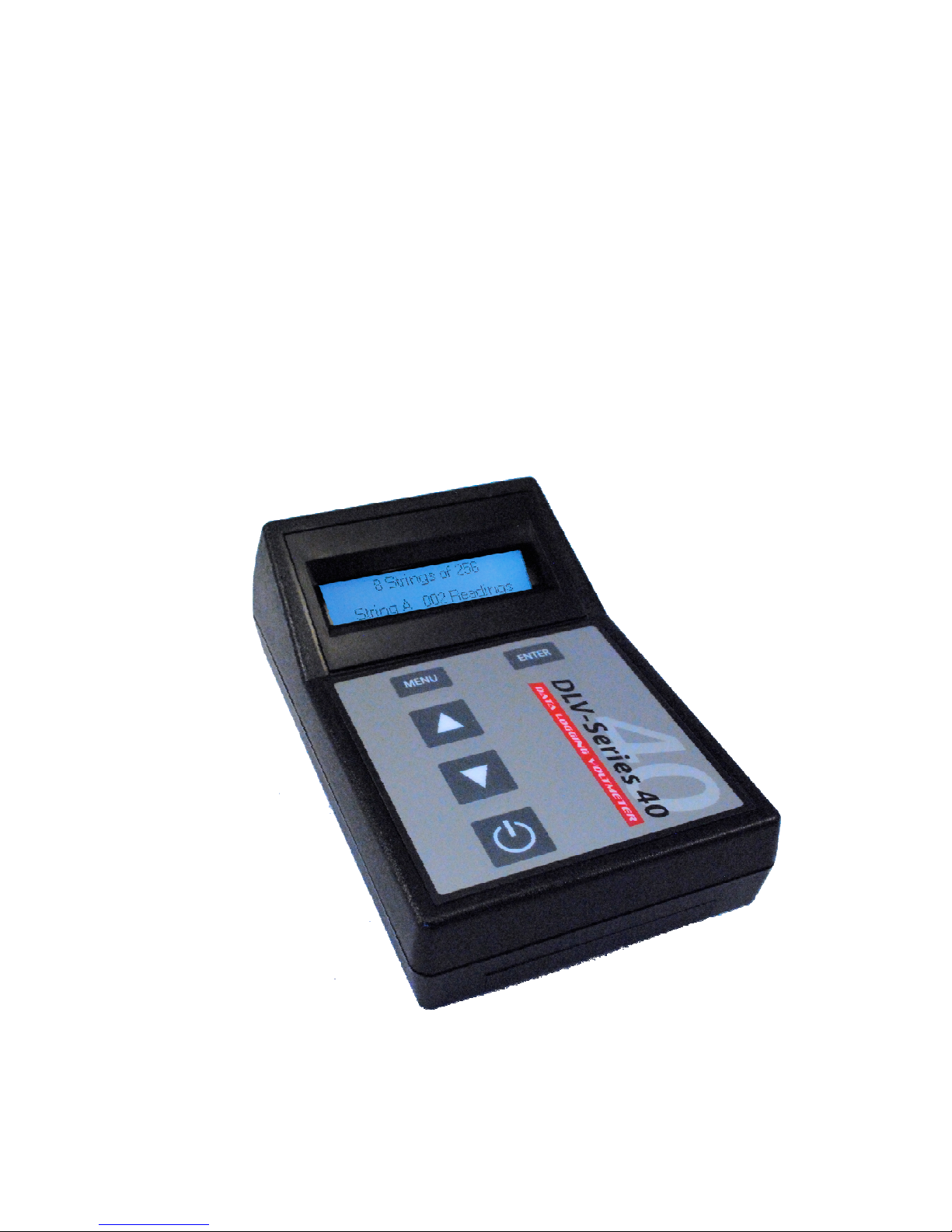
Explorer Group DLV40 User manual

Operator’s Manual:
DLV
40 Data logging Voltmeter
Rev: 02
Date: 5/28/2012
DLV40 Firmware: Rev 000.008 and above
Winmeter 5.0 Software: Rev 1.0.0 and above
Operator’s Manual:
40 Data logging Voltmeter
Operator’s Manual:
40 Data logging Voltmeter

Tab e of Contents:
1.0 Overview
1.1 User Interface
1.1.1 Graphica Back it LCD Disp ay (128x32)
1.1.2 Membrane Keypad
2.0 Menu System
2.1 Main Menu
2.2 Discharge Sub-Menu
2.3 “20 x 48” Sub-Menu
2.4 “8 x 256” Sub-Menu
3.0 Power Saving Features
3.2 Auto-Off
3.2 Low Battery Indication
3.3 Checking battery Vo tage
4.0 Taking a Measurement (ALL Modes)
4.1 Over Vo tage Indication (ALL Modes)
4.2 Recording Over a Previous Measurement (ALL Modes)
4.3 De eting a Previous Measurement (ALL Modes)
5.0 Discharge Test Procedure
5.1 Step1: Se ect DLV40 “Discharge Test” Mode & C ear Existing Test Data
5.1.1 Option 1: Using Winmeter 5.0 Software
5.1.2 Option 2: Manua y
5.2 Step 2: Measure String F oat Ce Vo tages
5.3 Step 3: Starting the Discharge Test Timer & Taking Discharge Readings
5.4 Step 4: Up oad Discharge Test Data to Winmeter 5.0
5.5 Step 5: Generate Ce Discharge Report(s)
5.6 Step 6: Save Ce Discharge Report(s)

6.0 F oat Test Procedure (“8x256” and “20x48” Modes)
6.1 Step1: Se ect DLV40 “8x256” /“20x48” Mode & C ear O d String Data
6.1.1 Option 1: Using Winmeter 5.0 Software
6.1.1 Option 2: Manua y
6.2 Step 2: Measure String F oat Ce Vo tages
6.3 Step 3: Up oad “8x256/20x48” Test Data to Winmeter 5.0
6.4 Step 4: Se ect F oat String to Save
6.5 Step 5: Generate Ce F oat Report(s)
6.5.1 Add/Edit Report Information and Parameters
6.5.2 View/Print Report(s)
6.5.2.1 Graphs
6.5.2.2 Tabu ar Report
6.5.2.3 Saving Report to PDF or Exce Format
6.5.3 Export Data to Exce (Optiona )
6.6 Step 6: Save Ce Test Report(s)
7.0 Connecting the DLV40 to PC/Winmeter 5.0
8.0 Upgrading DLV40 Firmware
For the most accurate results, please read and follow these instructions carefully.

1.0 Overview
The DLV40 data logging voltmeters have been designed specifically for the battery test industry. The
DLV40 is designed to measure and automatically record DC cell voltages between 0.1 VDC and 1 .
VDC (inclusive). It has a built in real time clock and calendar which allows for date and time stamping of
readings. The stored readings can then be transferred to a PC via a standard USB connection and the
companion Winmeter 5.0 Battery Analysis Software.
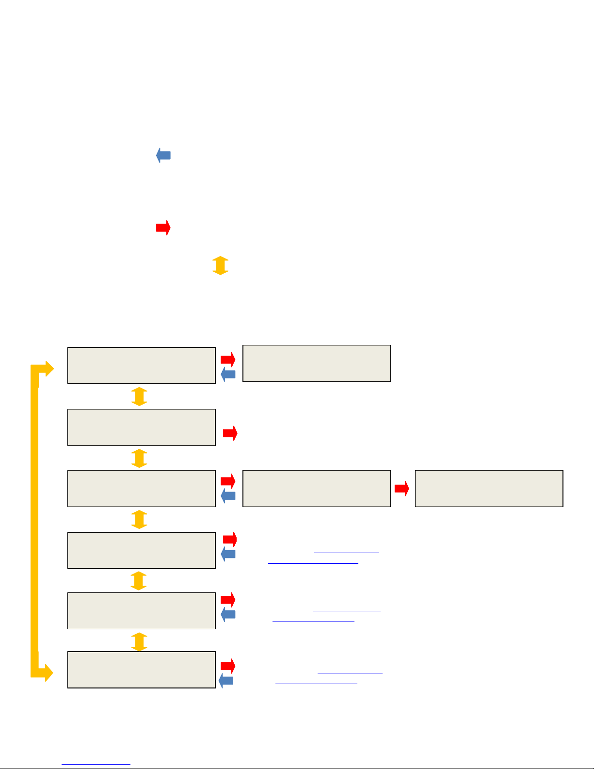
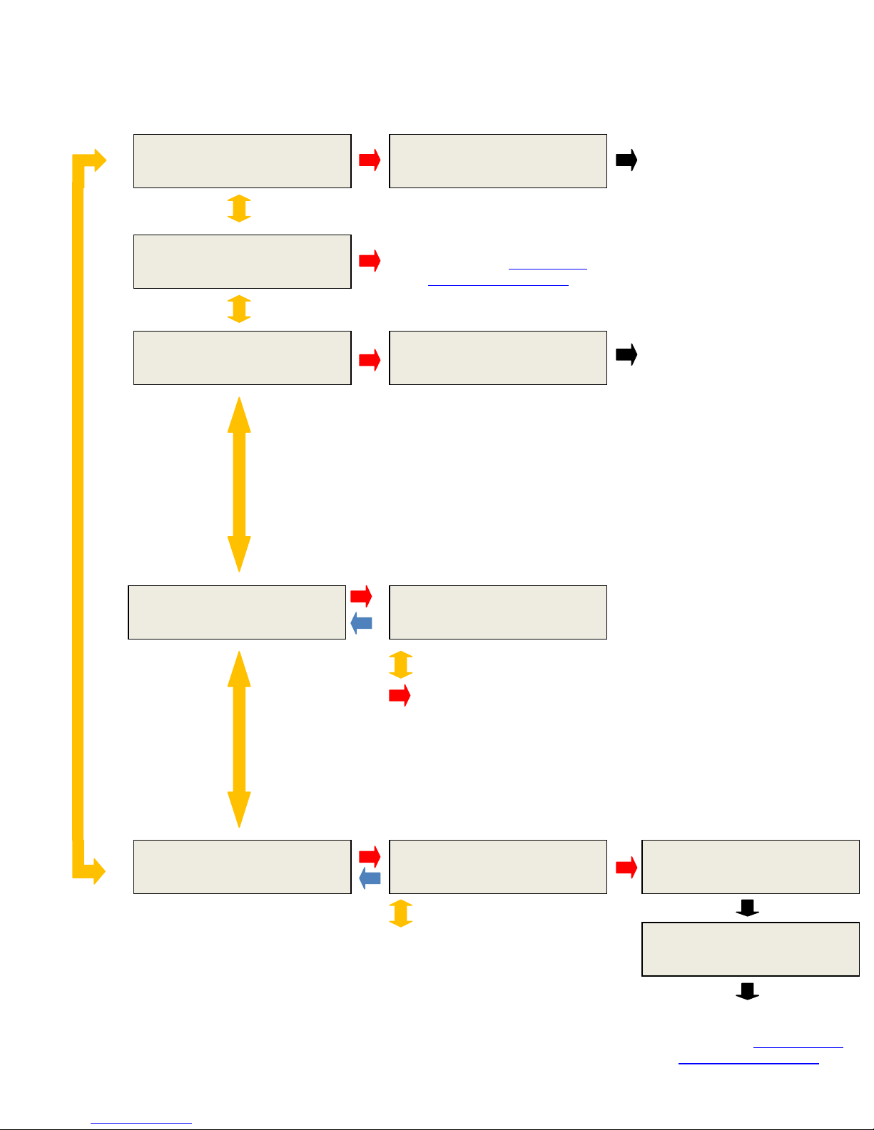
The DLV40 is capable of operating in (3) distinct measuring modes:
(i) “8 by 256” Mode: The DLV40 can measure and store up to 2048 readings of cell voltage.
These readings are stored in 8 separate data strings of 256 readings, denoted A through H.
The date and time of the last reading in each string is also recorded.
(ii) “20 by 48” Mode: The DLV40 can measure and store up to 60 readings of cell voltage.
These readings are stored in 20 separate data strings of 48 readings, denoted A through T.
The date and time of the last reading in each string is also recorded.
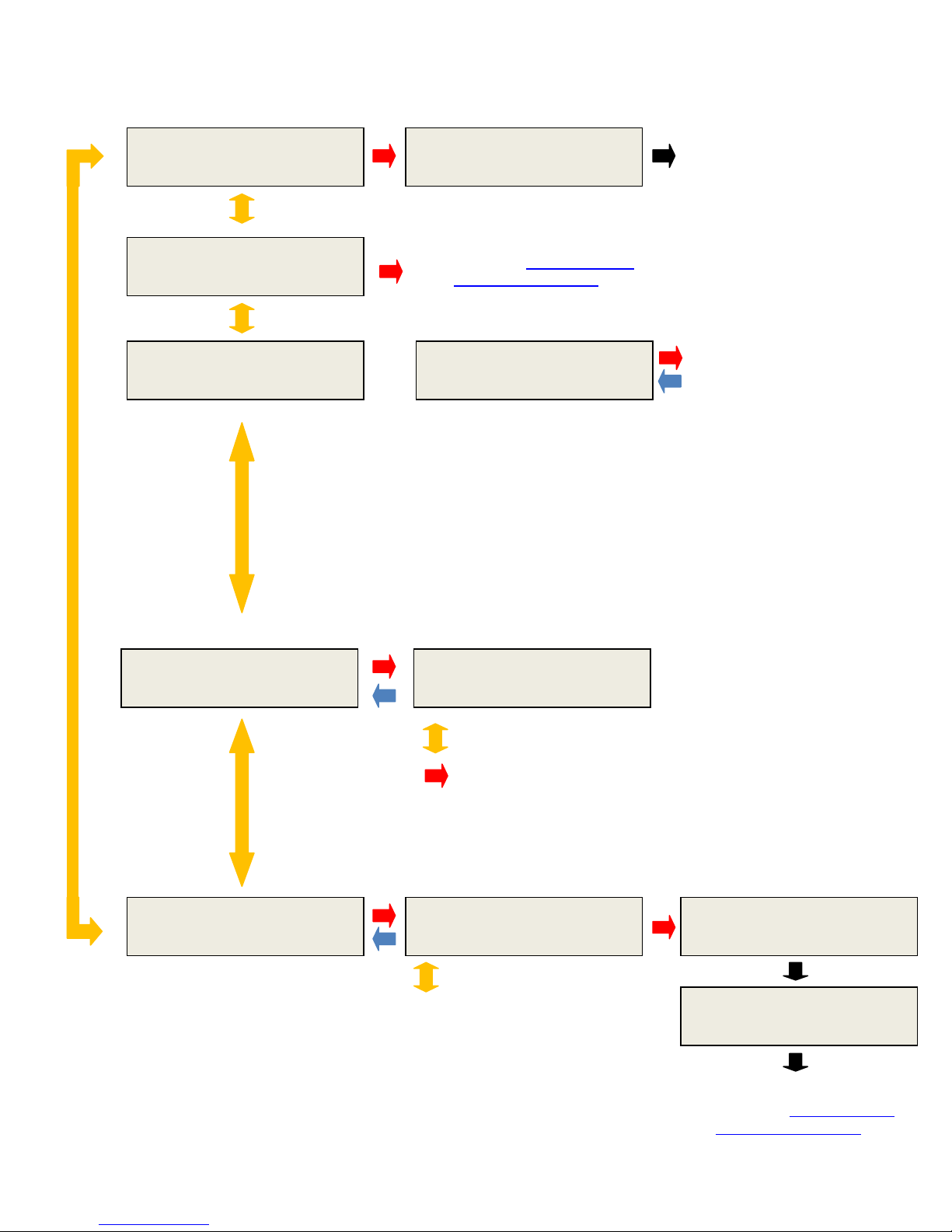
(iii) “Discharge Test” Mode: The DLV40 can measure and store up to 2048 readings of cell
voltage. These readings are stored in 8 separate data strings of 256 readings, denoted A
through H.
Readings in String A are reserved for the initial (f oat) voltage of the cell and are NOT time
stamped.
Readings in Strings “B” through “H” are reserved for cell voltages during the discharge (or
charge) test with each reading being time stamped to the nearest second from the start of
the discharge test. The date and time of the last reading is also recorded.
All stored readings can be downloaded via Winmeter 5.0 software to generate detailed test reports
including statistical and graphical analysis and then stored into a custom database. This software
communicates with the DLV40 via USB and allows the User to set the time/date, change modes, delete
data string(s) and upgrade the DLV40 firmware via PC interface.
All
DLV40 modes operate
independent
y
. Erasing the memory in one mode does
NOT
affect readings in the remaining (2) modes
.

1.1 User Interface
1.1.1 Graphica Back it LCD Disp ay (128x32)
1.1.2 Membrane Keypad
MENU
From measurement mode:
Push once to enter the
sub-menu.
Push twice to enter Main
menu.
ON/OFF:
“Short” push to turn ON
“Long” push to turn OFF
UP & DOWN
Main or sub menu mode:
Push to change the current
selection.
Measurement mode: Push
to change selected
readings.
ENTER
Push to accept the current
selection.
Dischg
0:00:03
+0.000
B:001
000.0
Sum of cell voltages
for the selected
string.
Shows 000.0 as no
discharge readings
have been taken.
Discharge Time
(Currently 3 seconds
into the test).
Selected String (“B”) and
the next reading in the
selected string (“001”).
(Float readings have been
taken but no discharge
readings have been
taken).
“Discharge Test”
Mode
Current measurement
mode.

2.0 Menu System
The DLV40 uses a simple two tier menu system. The “Main Menu” and (3) sub-menus, one for each
measurement mode (“8 by 256”, “20 by 48” and “Discharge Test”).
2.1 Main Menu
“MENU” Button:
When the DLV40 is in one of the measurement modes, push the MENU button once to enter the
appropriate sub-menu, push the MENU button a second time to enter the Main Menu.
When the DLV40 is in the Main Menu, push once to cancel the current selection.
“ENTER” Button:
Push the ENTER button to accept the current selection.
“UP” and “DOWN” Buttons:
In Main or sub-menu modes push to change the current selection.
In any of the (3) measurement modes push once to increment/decrement the cell pointer, push and
ho d to scroll through the readings.
*** Main Menu***
MODE : 8 by 256
*** Main Menu***
About DLV40
*** Main Menu***
Date & Time?
*** Main Menu***
De ete ALL Data
*** Main Menu***
MODE : DISCHARGE
*** Main Menu***
MODE : 20 by 48
DLV
40
Rev:
000.005
09-15-11 14:30:21
Battery 95% Ca : 06-15-11
Disp ays Date & Time
(Date/Time is set via USB
connection with Winmeter 5.0)
*** Main Menu***
De ete ALL Data?
*** Main Menu***
De ete Data 05%
Discharge Test Mode
(Please refer to Section 5.0 for the
Discharge Test Procedure )
20 by 48 Mode
(Please refer to Section 6.0 for the
Float Test Procedure(s) )
8 by 256 Mode
(Please refer to Section 6.0 for the
Float Test Procedure(s) )

2.2 “Discharge” Sub-Menu
*** Discharge Menu***
De ete B:003?
*** Discharge Menu***
Exit?
*** Discharge Menu***
Start DC Test?
*** Discharge Menu***
Change String?
*** Discharge Menu***
Print String?
Discharge Test Mode
(Please refer to Section 5.0 for the
Discharge Test Procedure )
*** Discharge Menu***
Print VDC String B?
*** Discharge Menu***
Printing Data…
*** Discharge Menu***
Printing Comp ete
Discharge Test Mode
(Please refer to Section 5.0 for the
Discharge Test Procedure
)
*** Discharge Menu***
Reading De eted
Discharge Test Mode
(Please refer to section X.X for
more information)
*** Discharge Menu***
De ete DC Test?
OR
Start/De ete Discharge Test
Please refer to section X.X (Start)
and section X.X (Delete) more
information.
Discharge Test
String A 024 Readings
UP/DOWN
to change strings
ENTER to select and return to
Discharge Test Mode
UP/DOWN
to change strings

2.3 “20 by 48” Sub Menu
*** 20 x 48 Menu ***
De ete J:025?
*** 20 x 48 Menu***
Exit?
*** 20 x 48 Menu***
Reading De eted
20 x 48 Test Mode
(Please refer to section X.X for
more information)
20 x 48 Test Mode
(Please refer to Section 6.0 for
the Float Test Procedure(s) )
*** 20 x 48 Menu***
De ete String J?
*** 20 x 48 Menu***
De eting String J…
20 x 48 Test Mode
(Please refer to section X.X for
more information)
*** 20 x 48 Menu***
Change String?
*** 20 x 48 Menu***
Print String?
*** 20 x 48 Menu***
Print VDC String J?
*** 20 x 48 Menu***
Printing Data…
*** 20 x 48 Menu***
Printing Comp ete
*** 20 x 48 Menu***
String J 024 Readings
UP/DOWN
to change strings
ENTER to select and return to
Discharge Test Mode
UP/DOWN
to change strings
20 x 48 Test Mode
(Please refer to Section 6.0 for
the Float Test Procedure(s) )

2.4 “8 by 256” Sub Menu
*** 8 x 256 Menu ***
De ete A:025?
*** 8 x 256 Menu***
Exit?
*** 8 x 256 Menu***
Reading De eted
8 x 256 Test Mode
(Please refer to section X.X for
more information)
8 x 256 Test Mode
(Please refer to Section 6.0 for
the Float Test Procedure(s) )
*** 8 x 256 Menu***
De ete String A?
*** 8 x 256 Menu***
De eting String A…
8 x 256 Test Mode
(Please refer to section X.X for
more information)
*** 8 x 256 Menu***
Change String?
*** 8 x 256 Menu***
Print String?
*** 8 x 256 Menu***
Print VDC String B?
*** 8 x 256 Menu***
Printing Data…
*** 8 x 256 Menu***
Printing Comp ete
*** 8 x 256 Menu***
String B 024 Readings
UP/DOWN
to change strings
ENTER to select and return to
Discharge Test Mode
UP/DOWN
to change strings
8 x 256 Test Mode
(Please refer to Section 6.0 to for
the Float Test Procedure(s) )

3.0 Taking a Ce Vo tage Measurement (ALL Modes)
Cell voltage measurements are taken in a similar fashion to a traditional voltmeter.
(i) Turn the DLV40 ON.
(ii) Select the required measurement mode (“20x48”, “8x256” or “Discharge”).
(Please refer to section X.X for Mode selection for more information)
(iii) Select required string.
For “20x48” or “8x256” mode:
- If old data is present, de ete string(s) data as required.
For “Discharge Test” mode:
If an old Discharge Test data is present, de ete the existing Discharge Test data.
The DLV40 is designed to measure absolute DC cell voltages between 0.1 VDC and 1 . VDC.
Attempts to measure higher DC voltages will result in an “OVERVOLTAGE!!!” warning.
8x256
+0.000
B:001
000.0
Sum of cell voltages
for the selected string
(shows 000.0 as no
discharge readings
have been taken).
Current measurement
mode.
Selected String (“B”) and
the next reading in the
selected string (“001”).
(No readings have been
taken).
When turned
ON
, the DLV40 will automatically resume in the previous mode and “point” to the next
reading location.
“20x48” or “8X256” Mode
Dischg 0:00:03
+0.000
B:001
000.0
Sum of cell voltages
for the selected string
(shows 000.0 as no
discharge readings
have been taken).
Discharge Time
(Currently 3 seconds
into the test)
.
Selected String (“B”) and
the next reading in the
selected string (“001”).
(Float readings have been
taken but no discharge
readings have been
taken).
“Discharge Test”
Mode
Current measurement
mode.
The DLV
40 USB cable
MUST
be
DISCONNECTED
whenever measuring voltages
!

(iv) Connect the voltage probes to the cell terminals.
The DLV40 automatically detects that it is connected to a cell and begins taking
measurements. When the readings are stab e (within +/- 0.005 VDC) the DLV40
automatically beeps, the back ight f ashes and the reading is he d on the display.
(v) Remove the voltage probes from the cell terminals.
The reading is he d on the display until the probes are removed. After approximately (1)
second the DLV40 stores the reading, adds the reading to the sum of string cell voltages and
increments to the next reading.
8x256 HLD
+2.345
B:001
000.0
Current measurement
mode.
Selected String (“B”) and
the next reading in the
selected string (“001”).
(No readings have been
taken).
“20x48” or “8X256” Mode
Dischg HLD
+2.345
B:001
000.0
Sum of cell voltages
for the selected
string.
(Shows 000.0 until
probes removed).
Readings “held” on
display until probes are
removed from cell
.
Selected String (“B”) and
the next reading in the
selected string (“001”).
(Float readings have been
taken but no discharge
readings have been
taken)
.
“Discharge Test”
Mode
Current measurement
mode.
8x256
+0.000
B:
002
002.3
Sum of cell voltages for
the selected string.
(Shows 002.3 as (1)
reading has been taken
.
Current measurement
mode.
Selected String (“B”) and
the next reading in the
selected string (“002”).
((1) reading has been
stored).
“20x48” or “8X256” Mode
Dischg 0:00:09
+0.000
B:
002
002.3
Discharge Time
(Now seconds into
the test)
.
“Discharge Test” Mode
Current measurement
mode.
Readings “held” on
display until probes are
removed from cell
.
Sum of cell voltages
for the selected
string.
(Shows 000.0 until
probes removed).
Sum of cell voltages for
the selected string.
(Shows 002.3 as (1)
reading has been
taken
).
Selected String (“B”) and
the next reading in the
selected string (“002”).
((1) reading has been
stored)
.

(vi) Repeat steps (iv) and (v) until all cell voltages in the string have been measured.
For “20x48” or “8x256” modes, please refer to Section 6.0 to for the Float Test Procedure(s).
For “Discharge Test” mode, please refer to Section 5.0 to for the Discharge Test Procedure.
3.1 Over Vo tage Indication (ALL Modes)
The DLV40 provides both an audio and visual indication if the probes are connected to an
excessive input voltage (Vin < -1 . VDC or Vin > +1 . VDC)
The unit will beep continuously and display:
This warning is removed as soon as the probes are disconnected from the high voltage source.
In
“Discharge Test”
mode:
- The string capacity of the discharge strings (B through H) is imited to the number of
readings in f oat string (String A).
- Once the last discharge reading is taken, (strings B through H), the DLV40 will automatically
increment to the next string.
- The user then must wait for the required test interval before taking the next set of discharge
cell voltage readings. The required test interval is typically ~Discharge test length divided by
(7)
OVER VOLTAGE!!!

3.2 Recording Over a Previous Measurement (ALL Modes)
To record over a previous measurement:
(i) Use the UP or DOWN buttons to scroll to the required reading location.
(ii) The currently stored reading is shown for approximately (2) seconds then the DLV40
reverts to measurement mode.
(iii) Connect the probes to the appropriate cell and take measurement.
The new reading replaces the o d reading in the se ected ce (B:003).
MEM
+2.156
B:
003
046.6
Current measurement
mode is replaced with
“MEM” to signify
reading is from memory
(B:003).
Selected String (“B”) and
the current reading in the
selected location (“003”).
8x256
+0.000
B:
020
046.6
Sum of cell voltages for
the selected string.
(Shows 046.6 if (20) ~
2.3 VDC readings have
been stored
).
Current measurement
mode.
Selected String (“B”) and
the next reading in the
selected string (“002”).
((1) reading has been
stored)
+2.156 are the current
readings stored in location
Sum of cell voltages for
the selected string.
(Shows 046.6 if (20) ~
2.3 VDC readings have
been stored
).
8x256
+0.000
B:003
046.6
Sum of cell voltages for
the selected string.
(Shows 046.6 if (20) ~
2.3 VDC readings have
been stored
).
Current measurement
mode.
Selected String (“B”) and
the next reading in the
selected string (“002”).
((1) reading has been
stored)
In
“Discharge Test”
mode:
- If the Discharge Test is already in progress and the selected readings are
in string B through H (discharge strings), then the timestamp for the
selected reading is also updated.

3.3 De eting a Previous Measurement (ALL Modes)
(i) Use the UP or DOWN buttons to scroll to the required reading location
(ii) The currently stored reading is shown for approximately (2) seconds then the DLV40
reverts to measurement mode.
(iii) Push the MENU button once to enter the measurement mode sub-menu and then use
the UP and DOWN arrows to select the delete measurement option.
(iv) Push the ENTER button to delete the selected reading.
MEM
+2.156
B:
003
046.6
Current measurement
mode is replaced with
“MEM” to signify
reading is from memory
(B:003).
Selected String (“B”) and
the current reading in the
selected location (“003”).
+2.156 is the current reading
stored in location B:003.
Sum of cell voltages for the
selected string.
(Shows 046.6 if (20) ~ 2.3
VDC readings have been
stored
).
8x256
+0.000
B:003
046.6
Sum of cell voltages for
the selected string.
(Shows 046.6 if (20) ~
2.3 VDC readings have
been stored
).
Current measurement
mode.
Selected String (“B”) and
the next reading in the
selected string (“002”)
((1) reading has been
stored)
** 8 x 256 Menu **
De ete B:003?
** 8 x 256 Menu **
Reading De eted
When a reading is deleted
,
ALL
readings in memory locations
above
the deleted cells
are mov
e
d
down
(1) location
.

4.0 Power Saving Features
4.1 Auto-Off
After approximately (3) minutes of non-operation, the unit will beep and display an auto-off warning
for 10 seconds. Pressing any button during the 10 seconds will cance the auto-off feature.
4.2 Low Battery Indication
A low battery is indicated by ay a “Low Battery!” prompt.The user can push “ENTER” to disregard but
is recommended that the battery is replaced before the next scheduled use.
4.3 Checking Battery Vo tage
To check the battery voltage at any time:
(i) If not in Main Menu, press the “MENU” button twice to enter the Main Menu:
(ii) Use the “UP” or “DOWN” buttons to select Discharge Test Mode:
Auto-off (10)
Note:
If a “Discharge Test” has been started, the DLV40 will continue to measure the time elapsed
since the discharge test was started.
In ALL modes, when turned ON the DLV40 will automatically start in the previous mode and
“point” to the next reading location.
*** Main Menu***
MODE : 8 by 256
*** Main Menu***
About DLV40

(iii) Press “ENTER” to select.
(iv) Press “MENU” to return to the main Menu.
DLV
40
Rev: 000.008
9-15-11 12:30:21
Battery 95% Ca : 6-15-11

5.0 Discharge Test Procedure
5.1 Step 1: Se ect DLV40 “Discharge Test” Mode & C ear Existing Test Data
5.1.1 Option 1: Using Winmeter 5.0 Software (Recommended)
(i) Connect the DLV40 to PC via USB
(ii) Once connected, the DLV40 will display “DLV40 <-> PC” and download data in its current
mode
If the Winmeter 5.0 AutoStart software is not enabled, RUN the
Winmeter 5.0 software to initiate data transfer of the current DLV40 mode
(“8 by 256”, “20 by 48” or “Discharge”).
Change mode of
operation
(if required)
If the “DLV40 & DMA35 USB Interface” does not initiate automatically
select “Down oad Device” -> “Via USB (search for device)”.

If the DLV40 is NOT in “Discharge Test” mode, the User can change to “Discharge Test” mode by the
selecting the “Charge/Discharge Test” radio button.
(iii) Once in “Discharge Test” mode:
(A) Select any/all strings (A-H) that contain data.
(B) Click the “De ete” button.
The DLV40 will then de ete ALL “Discharge Test” data.
(iv) Disconnect the USB cable from the DLV40.
Changing the DLV40 mode will cause the DLV40 to refresh data.
A
B
Select
Charge/Discharge
Test mode

5.1.2 Option 2: Manua y
(i) Turn the DLV40 ON.
Upon start-up the DLV40 will display the model number & firmware revision, the current
date and time and then the current test mode:
- “8 string of 256”, “8x256” in top left hand corner.
- “20 string of 48”, “20x48” in top left hand corner.
- “DISCHARGE”, “Dischg” in top left hand corner.
(ii) If NOT in “Discharge Test” mode:
A. Press the “MENU” button twice to enter the Main Menu:
B. Use the “UP” or “DOWN” buttons to scroll to “Discharge Test Mode”:
C. Press “ENTER” to select.
The DLV40 will change to “Discharge Test Mode” and display current mode information:
Current Mode
The DLV40 must
NOT
be connected to the PC via USB
!
8x256
+0.000
A:00
1
000.0
*** Main Menu***
MODE : 8 by 256
*** Main Menu***
MODE : DISCHARGE
DISCHARGE TEST
String A F oat V’s
Strings B->H D’chrge V’s
Current Test Mode

(iii) To DELETE ALL existing discharge test data:
A. Press the “MENU” button once to enter the Discharge Menu:
B. Use the “UP” or “DOWN” buttons to scroll to Discharge Test Mode:
Dischg F oat
+0.000
A:011
025.4
Discharge Test
String A : 010 Readings
String A is reserved for f oat voltages – cell voltage(s) BEFORE a load is
attached to the battery.
Strings B through H are reserved for discharge test cell voltages. Cell voltages
AFTER a load is attached to the battery.
As shown, String A contains 10 readings and hence there is existing Discharge
Test data and the DLV40 is not ready to start a new discharge test. See below
for instruction on deleting ALL existing discharge test data.
Current Test Mode
Selected String (“A”)
and next reading in the
selected string (“11”)
Sum of cell voltages for
the selected string.
Discharge Time
** Discharge Menu**
Print String?
** Discharge Menu **
De ete DC Test ?
Table of contents
Popular Measuring Instrument manuals by other brands

Steren
Steren AUT-CAP 1.0 instruction manual

Diamond Antenna
Diamond Antenna sx-1100 Operation instructions

Valcom
Valcom V9992 datasheet

ELGO Electronic
ELGO Electronic EMIX2 series operating manual

GESTRA
GESTRA NRT 2-1 Installation and service instructions

Magnescale
Magnescale DF800S Series instruction manual

Motortech
Motortech SparkView operating manual

PeakTech
PeakTech 5035 Operation manual

Vernier
Vernier Go Direct GDX-SPEC-FUV manual

Lignomat
Lignomat Ligno-VersaTec V-0 User instructions

ADA INSTRUMENTS
ADA INSTRUMENTS LASERMARKER 70 operating manual

PCB Piezotronics
PCB Piezotronics EX357E93/020NJ Service manual