manuals.online logo
Brands
  1. Home
  2. •
  3. Brands
  4. •
  5. EXPO
  6. •
  7. Transceiver
  8. •
  9. EXPO Bush Ranger User manual

EXPO Bush Ranger User manual

DELUXE 18CHANNEL
SSB/AM CB TRANSCEIVER
OWNER'S GUIDE
General Description
The Bush Ranger is a combination transmitter and receiver designed for
use in the Australian 27 MHz Citizens radio service. It is designed to meet
the Postal and Telecommunications Department requirements, RB249,
applicable to equipment in this service, and is not to be used for any
other purpose. P and T Form RB14 defines operation in this service and
the licensee is required to read and understand these regulations prior
to operating a CB transceiver.
A station license must be applied for by submitting a properly completed
Station License Application, Form RB13, as directed.
This unit will provide efficient and reliable radio communication in its
intended application if installed and operated in accordance with in-
structions contained herein.
Features
This transceiver is an advanced solid-state 2-way CB radio designed pri-
marily for mobile operation. It employs the very latest technology to
provide 18 transmit and receive channels in the 27 MHz band by means
of digital frequency synthesis with Phase Lock Loop [PLL] circuitry.
The transceiver can be operated over 18 channels in the conventional AM
mode or in suppressed carrier single sideband mode using either the
18 upper or 18 lower sideband channels, as desired. This not only triples
the effective number of operating channels from 18 to 54, but also
increases the effective range of transmission because all legal power is
concentrated in one sideband to provide 100% talk power. On receive,
the single sideband mode offers greatly improved sensitivity and selectivity;
this also contributes to an effective increase in operating range.
This transceiver also includes many features which will provide greater
operating convenience and assure optimum communications under a
wide range of conditions.
•
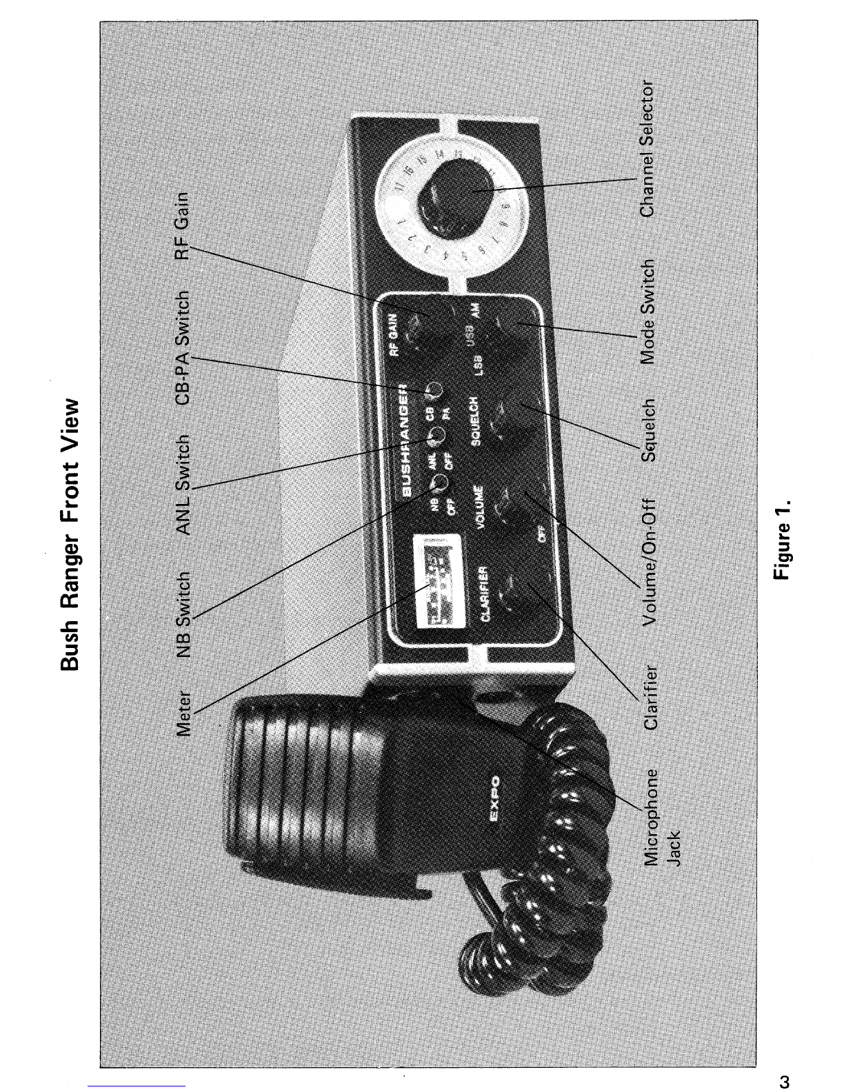
3-Position Mode Switch — selects AM, LSB and USB.
•
Illuminated Meter — indicates S units and RF Power Output.
•
Clarifier for fine-tuning on receive.
•
Variable Squelch Control.
•
Switchable RF Noise Blanker and Automatic Noise Limiter for effective
reduction of noise interference.
•
RF Gain Control.
•
Illuminated Channel Indicator.
•
Built-in Ceramic Filter provides razor-sharp selectivity — helps prevent
adjacent channel interference.
•
Provision for PA operation with volume control.
•
External Speaker Jack.
•
Push-to-talk dynamic mic with coiled cord and 5-pin DIN type plug.
•
Floating type chassis for negative or positive ground operation without
switching.
2
Fro
n
t
View
a)
•
-..
LL
3
Operating Controls and Features
[1]
Clarifier:
Permits slight adjustment of receiver tuning. Used for clarity
on SSB reception and fine tuning of stations on AM reception.
[2]
Volume/On-Off:
Varies the sound output from the speaker. Also incorporates
an on-off power switch at the extreme counter-clockwise
position.
[3]
Squelch Control:
This control is used to eliminate any annoying background
noise when no signals are present. The degree of sensitivity
to incoming signals is adjustable. When the Squelch control
is rotated to the fully clockwise position, it provides maxi-
mum squelch, in the fully counter-clockwise position it
provides minimum squelch.
[4]
Mode Switch:
Selects mode of operation — lower sideband, upper sideband
or standard AM.
[5]
Channel Selector:
Rotary switch selects one of 18 channels for transmit and
receive operation.
[6]
ANL Switch:
Activates automatic noise limiter for reduction of atmospheric
noises.
[7]
RF Gain Control:
Used as gain control when receiving SSB signals, normally set
to maximum when receiving AM.
[8]
CB-PA Switch:
Used to switch unit to CB or PA mode.
[9]
NB Switch:
NB position selects special RF noise silencing circuit to
combat ignition noise.
[10]
Meter:
Illuminated meter indicates relative incoming signal strength
when receiving and relative RF power output when transmit-
ting.
[11 Microphone Socket:
5-pin DIN socket for attachment of push-to-talk microphone
[supplied].
Self-tapping Screws
(use 4 at least}
Securing Screws
Mobile Installation
Transceiver Mounting
Before installing the transceiver in a car, truck, boat, etc., be sure to
choose a location which is convenient to the operating controls, and will
not interfere with the normal functions of the driver. The transceiver
may be mounted to the underside of the instrument panel or dashboard
of a car, truck, etc., by means of the special bracket that is supplied with
the transceiver [See Figure 2] .
Attach the bracket to the underside of the instrument panel or dashboard
of the vehicle using the self-tapping screws supplied. Then attach the
transceiver to the bracket by means of the two knurled securing screws
at the sides. Tilt the unit upward or downward to the desired angle before
tightening the securing screws.
Figure 2. Mobile Installation
5
12V Battery
Positive (+) Terminal
+NM

To DC Power Socket
on the Transceiver
DC Power Connections
The transceiver is designed to operate from a battery source of 13.8 volts,
DC, in vehicles [or boats] employing either negative or positive ground
electrical systems. The fused DC power cable supplied is used to make
the necessary power connection to the transceiver. The
red [fused]
lead is
connected to the
positive [+]
side of the electrical system in the vehicle,
and the
back lead
is connected to the
negative [—]
side of the system.
In a negative ground vehicle, connect the
red lead
to the hot point in the
electrical system
[battery positive],
and the
black leadto
the metal firewall
or any other point that is connected to the vehicle chassis
[battery
negative]. In
a positive ground vehicle, connect the black lead to the hot
point in the electrical system
[battery negative],
and the red lead to the
metal firewall or any other point that is connected to the vehicle chassis
[battery positive] .
A suitable point in the vehicle for connection to the
hot, battery side can usually be found on the fuse block.

Since the
transceiver draws a maximum of only 2.5 ampere of current, you can
use a terminal which supplies power to the radio or other accessory
[use the unfused input side since the DC power cable is equipped with
its own fuse]. To simplify connection to this terminal, attach an alligator
12V Battery
Negative (—) Terminal
Figure 3.
[spring] clip to the power lead first and then clamp it onto the terminal
selected. Be sure to make the power connection to a point which will cut
off DC power to the transceiver when the vehicle ignition is turned off.
Note:

The transceiver requires 13.8 volts DC to develop full rated
RF
power output.
When you have completed the connections of the red and black leads of
the DC power cables as just indicated, attach the 3-pin female plug at the
other end of the power cable to the matching male power connector at
the rear of the transceiver. Note that the plug can be inserted in only
one direction due to the unequal spacing between pins.
Antenna Connection
The lead-in cable from the CB antenna should be terminated with a
PL-259 type male connector. Attach to the matching antenna input
connector at the rear of the transceiver.
Microphone Bracket
The small size of the transceiver prohibits mounting a microphone bracket
directly to the chassis. We recommend, therefore, that the microphone
bracket be attached to the dashboard of the vehicle or in any other
convenient location. If one desires to do this without drilling holes, a
magnetic mounting plate may be used and the microphone bracket
attached to it.
Microphone Connection
Insert the 5-pin plug at the end of the coiled cord into the microphone
socket at the left side of the transceiver.
CB Antennas
The results obtained with your
Bush Ranger
Citizens Band Transceiver
will be greatly determined by the efficiency of the antenna system used.
Due to the complexity of the subject, it is not within the scope of this
manual to provide detailed information on antenna systems. We suggest
that you purchase one of the numerous books available which covers
this subject in greater detail.
Antenna Cable
RG-58/U
cable is generally used to connect the CB antenna to the trans-
ceiver. The cable should be terminated with a PL-259 connector for
connection to the antenna input on the transceiver.
7
Operating Instructions
Make sure the transceiver is properly installed as indicated previously,
and that the antenna and power source are connected. If you have not
already done so, plug in the microphone.
Receiving
1.
Rotate the Squelch control to the counter-clockwise position
initially.
2.
Set the CB-PA Switch to the CB position.
3.
Set the RF Gain control to maximum [fully clockwise].
4.
Set the Clarifier control to the center [12 o'clock pbsition].
5.
Set the Mode Switch to either AM for standard AM reception or to
LSB
or USB, depending on whether signal to be received is on the
upper or lower sideband.
6.
Select desired channel [1-18] by rotating the Channel Selector
Switch to the desired position.
7.
Set the NB Switch to the Off position initially.
8.
Rotate the Volume/On-Off Switch clockwise to apply power to
the transceiver. Since the transceiver is fully transistorized, operation
will be instantaneous. Continue rotating the Volume/On-Off Switch
clockwise to provide a comfortable listening level.
S/P
-
RF Meter [AM and SSB Reception]
During reception, this meter provides a relative indication of the signal
strength of a received signal in S units. During reception of AM signals
the meter will indicate in the conventional manner, in accordance with
the RF carrier signal received. However, during reception of SSB signals
the meter will respond only during voice modulation, this being due to
the fact that SSB transmissions do not contain a continuous RF carrier,
as is found on AM.
Squelch Control [AM and SSB Reception]
The Squelch control is used to eliminate any annoying background noise
when no signals are present. To adjust the Squelch control properly during
_reception, turn up Volume until background noise is heard [no signal
should be present]. Rotate the Squelch slowly clockwise until the back-
ground noise just disappears. At this point, the receiver will be quiet under
no-signal conditions, but an incoming signal will overcome the squelch
action and be heard. Since this control is variable, it can be used to
8
provide varying degrees of sensitivity to incoming signals. As the control
is advanced [from counterclockwise position ], the squelch action is
progressively increased and progressively stronger incoming signals are
needed to overcome it. To receive extremely weak signals or to disable
the squelch circuit, simply turn the control fully counterclockwise.
Clarifier [AM and SSB]
This control provides fine tuning of the receiver by ±800 Hz. On AM
reception, this will permit slight adjustment of your tuning in cases
where the received signal is slightly off frequency. For SSB reception,
this control is used as a voice clarifier by tuning it over the indicated area
for clearest, most intelligible voice.
Noise Blanker
Your transceiver is equipped with a special RF noise blanker [NB] which
will be found highly effective in combating auto ignition noise. The RF
noise blanker is a unique circuit which, when switched in, literally
chops out ignition noise by silencing the receiver for the brief duration
of each noise impulse. The period during which the receiver is silenced
is of such short duration [10 microseconds or less] that there is virtually
no audible effect on the output. You nay notice a lower reading on the
S meter when you switch the blanker into the circuit. This is caused
by the reduction of noise passing through the receiver IF stages, and does
not indicate a reduction in the actual signal which is virtually unaffected
by the Noise Blanker [you may notice a slight hissing noise, however].
Note:

The RF Noise Blanker is not designed for use against interference
caused by neons, atmospherics and various types of electrical
machinery.
RF Gain Control
During AM reception, this control is normally left at maximum, the
speaker output level being adjusted by means of the
VOLUME
control.
During
SSB
reception, the
VOLUME
control should be set to about the
mid position [12 o'clock] initially and the output level adjusted by means
of the RF. Gain control.

If necessary, readjust the setting of the
Volume control to produce proper gain control action with the
RF
Gain control.
9
External Speaker Jack
The recommended plug for the
EXT SP
jack is a subminiature phone
plug [3.5 mm0]. The impedance of earphones or speakers connected to
this jack should be 8 to 16 ohms. Insertion of a plug into the jack auto-
maticapy silences the internal speaker.
Transmitting on AM and SSB
Warning:

Never attempt to transmit without an antenna or load.
Transmitting with this unit on any of the 18 CB channels requries no
unusual procedures except that you must first select one of the three
modes of operation possible, AM, upper sideband or lower sideband.
If you are attempting to communicate with a station having a similar
transceiver to yours, you can make initial contact on AM and then
arrange to conduct subsequent communications in one of the sideband
modes, either upper or lower sideband. Of course, if the other station
is only capable of AM reception, you will also have to transmit in the
AM mode. After you have selected the desired mode of operation by
means of the AM-USB-LSB selector switch, simply depress the push-to-
talk button on the microphone to transmit. Hold the microphone 3 to
4 inches from the mouth and slightly to one side so that the voice does
not project directly into the microphone [this provides best results].
Speak at a normal level — there is no need to raise your voice or shout
into the microphone. During periods of transmission, the receiver is
silenced and reception is therefore impossible. In the same way, your
signal cannot be heard by another station when he is transmitting —
each must take turns. To receive again, simply release the microphone
push-to-talk button.
S/P-RF Meter Indications
On AM, the
S/P-RF
meter will immediately indicate as soon as you press
the push-to-talk button on the microphone, showing that the unit is
transmitting an RF carrier. When the push-to-talk button is pressed while
in the single sideband mode, the meter will produce no reading until
you speak into the microphone and provide modulation. The meter
pointer will then fluctuate in accordance with your voice as you transmit
the single sideband signal. It should be noted that the meter will indicate
approximate power output only when connected to a 50 ohm resistive
load. If the antenna and transmission line do not offer such a load the
meter cannot be used as a true indication of power output.
10
Citizens Band Frequencies
Your transceiver is capable of operation on all presently available Australian
CB frequencies for which are listed as follows.
New
Australian
Channel
Frequency
Previous
USA
Channel
1
27.015 MHz
5
2
27.025 MHz
6
3
27.035 MHz
7
4
27.055 MHz
8
5
*
27.065 MHz
9
6
**
27.085 MHz
11
7
27.095 MHz
Not alloc.
8
27.105 MHz
12
9
27.115 MHz
13
10
27.125 MHz
14
11
27.135 MHz
15
12
27.155 MHz
16
13
27.165 MHz
17
14
27.175 MHz
18
15
27.185 MHz
19
16
27.195 MHz
Not alloc.
17
27.205 MHz
20
18
27.225 MHz
22
* Channel 5 shall be used for emergency.
** Channel 6 shall be used for calling.
11
PA [Public Address] Operation
Special provision has been made for Public Address [PA] operation utiliz-
ing the microphone and audio stages in the transceiver. For PA operation,
you should use an external 8-16 ohm speaker connected to the PA jack
[located at the rear of the transceiver]. The recommended plug for the
PA jack is a subminiature phone plug [3.5 mm0]. To set the transceiver
to the PA mode, set the CB/PA switch to the PA position to operate the
PA circuit, then press the push-to-talk button on the microphone and
talk into it — your voice will be heard from the external speaker [which
may be mounted on the exterior of a car or building].
Note:

During PA operation, the Volume control can be used to adjust
the speaker output level.
To reduce acoustic feedback when the PA speaker is mounted on a car
or truck, you may have to close the vehicle windows, or•reduce the volume
as necessary to stop any feedback that may occur.
12
i
3
USRC
41\16-
4.
Schematic Diagram
Figure 4.

13
Expo International Pty. Ltd.
47-49 Buckley Street
Marrickville 2204
Australia
Printed in Japan
(KTBURNGRXX)

Popular Transceiver manuals by other brands

ELECRAFT K3 manual

ELECRAFT

ELECRAFT K3 manual

QRP Labs QCX-mini Assembly instructions

QRP Labs

QRP Labs QCX-mini Assembly instructions

Kenwood VHF P25 Transceiver TK-5710 Service manual

Kenwood

Kenwood VHF P25 Transceiver TK-5710 Service manual

Williams Sound Digi-Wave DLT-100 user guide

Williams Sound

Williams Sound Digi-Wave DLT-100 user guide

LYNXTechnik yellobrik OTR 1240 quick reference

LYNXTechnik

LYNXTechnik yellobrik OTR 1240 quick reference

Kenwood TS-940S instruction manual

Kenwood

Kenwood TS-940S instruction manual

SVSi N4321 quick start guide

SVSi

SVSi N4321 quick start guide

Yaesu FTM-300DR instruction manual

Yaesu

Yaesu FTM-300DR instruction manual

Midland 77-250CXL owner's manual

Midland

Midland 77-250CXL owner's manual

ozQRP MST3 Construction and operation manual

ozQRP

ozQRP MST3 Construction and operation manual

Kenwood TK-7360H instruction manual

Kenwood

Kenwood TK-7360H instruction manual

Venus SW-3B quick start guide

Venus

Venus SW-3B quick start guide

Telos Zephyr Xport user guide

Telos

Telos Zephyr Xport user guide

Yaesu FT-411 MKII operating manual

Yaesu

Yaesu FT-411 MKII operating manual

Kenwood TK-3160 Service manual

Kenwood

Kenwood TK-3160 Service manual

NXP Semiconductors MKW01Z128 Reference manual

NXP Semiconductors

NXP Semiconductors MKW01Z128 Reference manual

Vertex FTL-1014 operating manual

Vertex

Vertex FTL-1014 operating manual

Vertex Standard VX-261 operating manual

Vertex Standard

Vertex Standard VX-261 operating manual

manuals.online logo
manuals.online logoBrands
  • About & Mission
  • Contact us
  • Privacy Policy
  • Terms and Conditions

Copyright 2025 Manuals.Online. All Rights Reserved.